Vol. 01, No. 01, Jan-Dec 2012
Three leg VSC Based DSTATCOM and T-Connected Transformer for
Power Quality Improvement
G.
K
EERTHANA andS.
D
ILEEPK
UMARV
ARMADepartment of Electrical & Electronics Engg. Shri Vishnu Engg. College for Women, A.P., India Email: [email protected], [email protected]
Abstract: In this paper, a new three-phase four-wire distribution static compensator (DSTATCOM) based on a T-connected transformer and a three-leg voltage source converter (VSC) is proposed for power quality improvement. The T-connected transformer connection mitigates the neutral current and the three-leg VSC compensates harmonic current, reactive power, and balances the load. Two single-phase transformers are connected in T-configuration for interfacing to a three-phase four-wire power distribution system and the required rating of the VSC is reduced. The insulated gate bipolar transistor (IGBT) based VSC is supported by a capacitor and is controlled for the required compensation of the load current. The dc bus voltage of the VSC is regulated during varying load conditions. The DSTATCOM is tested for power factor correction and voltage regulation along with neutral current compensation, harmonic elimination, and balancing of linear loads as well as nonlinear loads. The performance of the three-phase four wires DSTATCOM is validated using MATLAB software with its Simulink and power system blockset toolboxes.
Keywords: Distribution static compensator (DSTATCOM); neutral current compensation; power quality improvement; T-connected transformer; voltage source converter (VSC).
Introduction:
Three-Phase four-wire distribution systems are facing severe power quality problems such as poor voltage regulation, high reactive power and harmonics current burden, load unbalancing, excessive neutral current, etc. Three-phase four-wire distribution systems are used in commercial buildings, office buildings, hospitals, etc. Most of the loads in these locations are nonlinear loads and are mostly unbalanced loads in the distribution system. This creates excessive neutral current both of fundamental and harmonic frequency and the neutral conductor gets overloaded. The voltage regulation is also poor in the distribution system due to the unplanned expansion and the installation of different types of loads in the existing distribution system.
In order to control the power quality problems, many standards are proposed, such as the IEEE-519 standard. There are mitigation techniques for power quality problems in the distribution system and the group of devices is known by the generic name of custom power devices (CPDs). The distribution static compensator (DSTATCOM) is a shunt-connected CPD capable of compensating power quality problems in the load current. Some of the topologies of DSTATCOM for three phase four-wire system for the mitigation of neutral current along with power quality compensation in the source current are four-leg voltage source converter (VSC), three single-phase VSCs, three-leg VSC with split capacitors, three-leg VSC with zig-zag transformer, and three-leg VSC with neutral terminal at the positive or negative of dc bus.
The voltage regulation in the distribution feeder is improved by installing a shunt compensator. There are many control schemes reported in the literature for control of shunt active compensators such as instantaneous reactive power theory, power balance theory, synchronous reference frame theory, symmetrical components based, etc. The synchronous reference frame theory is used for the control of the proposed DSTATCOM.
System configuration and design:
The shunt-connected DSTATCOM based distribution system. The dc capacitor connected at the dc bus of the converter acts as an energy buffer and establishes a dc voltage for the normal operation of the DSTATCOM system. The DSTATCOM can be operated for reactive power compensation for power factor correction or voltage regulation.
Fig.1: (a) single-line diagram of DSTATCOM system. (b)Phasor diagram for UPF operation
(c) ZVR operation.
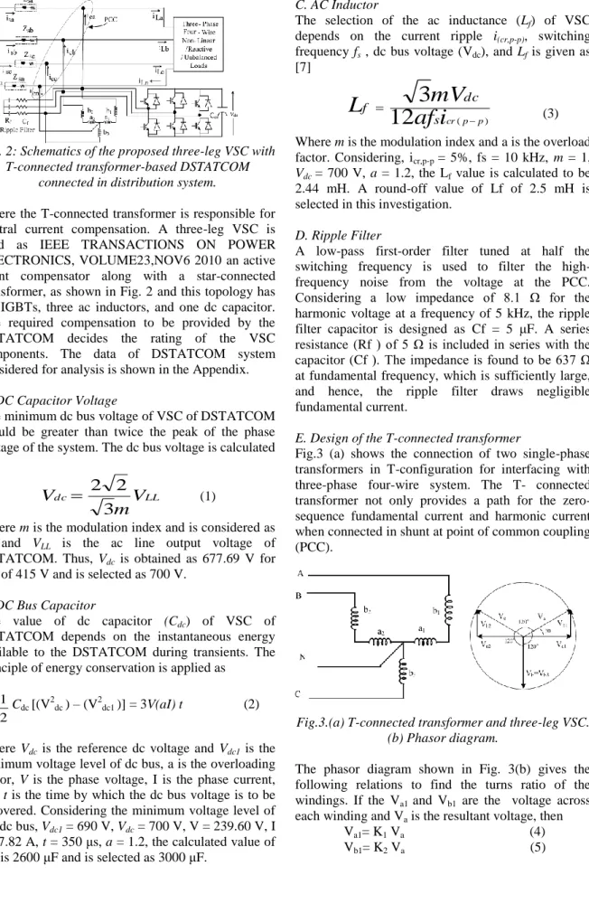
Fig. 2: Schematics of the proposed three-leg VSC with T-connected transformer-based DSTATCOM
connected in distribution system.
Where the T-connected transformer is responsible for neutral current compensation. A three-leg VSC is used as IEEE TRANSACTIONS ON POWER ELECTRONICS, VOLUME23,NOV6 2010 an active shunt compensator along with a star-connected transformer, as shown in Fig. 2 and this topology has six IGBTs, three ac inductors, and one dc capacitor. The required compensation to be provided by the DSTATCOM decides the rating of the VSC components. The data of DSTATCOM system considered for analysis is shown in the Appendix. A. DC Capacitor Voltage
The minimum dc bus voltage of VSC of DSTATCOM should be greater than twice the peak of the phase voltage of the system. The dc bus voltage is calculated as LL dc
V
m
V
3
2
2
(1)Where m is the modulation index and is considered as 1, and VLL is the ac line output voltage of
DSTATCOM. Thus, Vdc is obtained as 677.69 V for
VLL of 415 V and is selected as 700 V.
B. DC Bus Capacitor
The value of dc capacitor (Cdc) of VSC of
DSTATCOM depends on the instantaneous energy available to the DSTATCOM during transients. The principle of energy conservation is applied as
2 1 C
dc [(V2dc ) – (V2dc1 )] = 3V(aI) t (2)
Where Vdc is the reference dc voltage and Vdc1 is the
minimum voltage level of dc bus, a is the overloading factor, V is the phase voltage, I is the phase current, and t is the time by which the dc bus voltage is to be recovered. Considering the minimum voltage level of the dc bus, Vdc1 = 690 V, Vdc = 700 V, V = 239.60 V, I
= 27.82 A, t = 350 μs, a = 1.2, the calculated value of Cdc is 2600 μF and is selected as 3000 μF.
C. AC Inductor
The selection of the ac inductance (Lf) of VSC
depends on the current ripple i(cr,p-p), switching
frequency fs , dc bus voltage (Vdc), and Lf is given as
[7] ) (
12
3
p p cri
af
mV
L
s dc f (3)Where m is the modulation index and a is the overload factor. Considering, icr,p-p = 5%, fs = 10 kHz, m = 1,
Vdc= 700 V, a = 1.2, the Lf value is calculated to be
2.44 mH. A round-off value of Lf of 2.5 mH is selected in this investigation.
D. Ripple Filter
A low-pass first-order filter tuned at half the switching frequency is used to filter the high-frequency noise from the voltage at the PCC. Considering a low impedance of 8.1 Ω for the harmonic voltage at a frequency of 5 kHz, the ripple filter capacitor is designed as Cf = 5 μF. A series resistance (Rf ) of 5 Ω is included in series with the capacitor (Cf ). The impedance is found to be 637 Ω at fundamental frequency, which is sufficiently large, and hence, the ripple filter draws negligible fundamental current.
E. Design of the T-connected transformer
Fig.3 (a) shows the connection of two single-phase transformers in T-configuration for interfacing with three-phase four-wire system. The T- connected transformer not only provides a path for the zero-sequence fundamental current and harmonic current when connected in shunt at point of common coupling (PCC).
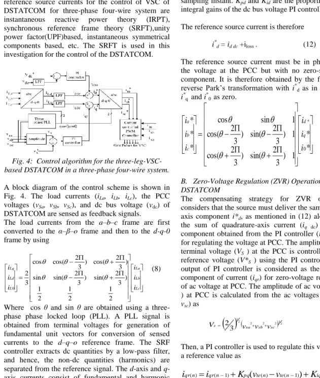
Fig.3.(a) T-connected transformer and three-leg VSC. (b) Phasor diagram.
The phasor diagram shown in Fig. 3(b) gives the following relations to find the turns ratio of the windings. If the Va1 and Vb1 are the voltage across
each winding and Va is the resultant voltage, then
Va1= K1 Va (4)
Where K1 and K2 are the fractions of windings in
phases. Considering
v
a
v
b
v
and Va1=Va cos300, and Vb1=Va sin300, then from (4) and (5), one
gets, K1=0.866 and k2=0.5.
The line voltage is Vca=415v
Va=Vb=Vc=
239
.
60
V
3
415
(6) Va1=207.49 V, Vb1=119.80V. (7) Control of DSTATCOM:The control approaches available for the generation of reference source currents for the control of VSC of DSTATCOM for three-phase four-wire system are instantaneous reactive power theory (IRPT), synchronous reference frame theory (SRFT),unity power factor(UPF)based, instantaneous symmetrical components based, etc. The SRFT is used in this investigation for the control of the DSTATCOM.
Fig. 4: Control algorithm for the three-leg-VSC-based DSTATCOM in a three-phase four-wire system. A block diagram of the control scheme is shown in Fig. 4. The load currents (iLa, iLb, iLc), the PCC
voltages (vSa, vSb, vSc), and dc bus voltage (vdc) of
DSTATCOM are sensed as feedback signals. The load currents from the a–b–c frame are first converted to the α–β–o frame and then to the d-q-0 frame by using Lc Lb La L Ld Lq i i i i i i 2 1 2 1 2 1 ) 3 2 sin( ) 3 2 sin( sin ) 3 2 cos( ) 3 2 cos( cos 3 2 0 (8)
Where cos θ and sin θ are obtained using a three-phase three-phase locked loop (PLL). A PLL signal is obtained from terminal voltages for generation of fundamental unit vectors for conversion of sensed currents to the d–q–o reference frame. The SRF controller extracts dc quantities by a low-pass filter, and hence, the non-dc quantities (harmonics) are separated from the reference signal. The d-axis and q-axis currents consist of fundamental and harmonic components as
iLd = id dc + id ac (9)
iLq = iq dc + iq ac (10)
A. UPF Operation of DSTATCOM
The control strategy for reactive power compensation for UPF operation considers that the source must deliver the mean value of the direct-axis component of the load current along with the active power component current for maintaining the dc bus and meeting the losses (iloss) in DSTATCOM. The output
of the proportional-integral (PI) controller at the dc bus voltage of DSTATCOM is considered as the current (iloss) for meeting its losses
) ( ) 1 ( ) ( ) 1 ( ) (n lossn pd( dcn dcn
)
id den lossi
k
v
v
k
v
i
(11)Where vde(n) = v*dc− vdc(n) is the error between the
reference v*dc and sensed vdc voltages at the nth
sampling instant. Kpd and Kid are the proportional and
integral gains of the dc bus voltage PI controller. The reference source current is therefore
i*d = id dc +iloss . (12)
The reference source current must be in phase with the voltage at the PCC but with no zero-sequence component. It is therefore obtained by the following reverse Park’s transformation with i*d as in (12) and
i*q and i*0 as zero.
*
*
1
)
3
2
sin(
)
3
2
cos(
1
)
3
2
sin(
)
3
2
cos(
1
sin
cos
*
*
*
0 *i
i
i
i
i
i
q d c b a
(13)B. Zero-Voltage Regulation (ZVR) Operation of DSTATCOM
The compensating strategy for ZVR operation considers that the source must deliver the same direct-axis component i*d, as mentioned in (12) along with
the sum of quadrature-axis current (iq dc) and the
component obtained from the PI controller (iqr ) used
for regulating the voltage at PCC. The amplitude of ac terminal voltage (VS ) at the PCC is controlled to its
reference voltage (V*S ) using the PI controller. The
output of PI controller is considered as the reactive component of current (iqr) for zero-voltage regulation
of ac voltage at PCC. The amplitude of ac voltage (VS
) at PCC is calculated from the ac voltages (vsa, vsb,
vsc) as
2
2 2 2
12 1 3 2 sc sb sa s v v v V (14) Then, a PI controller is used to regulate this voltage to a reference value as ) ( ) 1 ( ) ( ) 1 ( ) (n qrn pq(
ten ten)
iq ten qri
K
v
v
K
v
i
(15)Where vte(n) = VS − VS(n) denotes the error between
reference (V*S ) and actual (VS(n) ) terminal voltage
amplitudes at the nth sampling instant. Kpq and Kiq are
the proportional and integral gains of the dc bus voltage PI controller. The reference source quadrature-axis current is
i*q = iqdc + iqr . (16)
The reference source current is obtained by reverse Park’s transformation using (13) with i*d as in (12)
and i*q as in (16) and i*0 as zero.
C. Computation of Controller Gains
The gains of the controllers are obtained using the Ziegler–Nichols step response technique. A step input of amplitude (U) is applied and the output response of the dc bus voltage is obtained for the open-loop system. The maximum gradient (G) and the point at which the line of maximum gradient crosses the time axis (T) are computed. The gains of the controller are computed using the following equations:
GT U p
K
1.2 (17) GT U iK
0.62 (18)Fig. 5: Previous Method of MATLAB model of the T-connected transformer and the three-leg- VSC-based
DSTATCOM-connected system. D. Current-Controlled Pulse Width Modulation (PWM) Generator
In a current controller, the sensed and reference source currents are compared and a proportional controller is used for amplifying current error in each phase before comparing with a triangular carrier signal to generate the gating signals for six IGBT switches of VSC of DSTATCOM.
Modeling and simulation:
The three-leg VSC and the Star-connected transformer based DSTATCOM connected to a three-phase four-wire system is modeled and simulated using the MATLAB with its Simulink and PSBs. The ripple filter is connected to the DSTATCOM for filtering the ripple in the PCC voltage. The MATLAB-based model of the three-phase four-wire DSTATCOM is shown in Fig. 5. The Star -connected transformer in parallel to the load, the three-phase source, and the shunt-connected three-leg VSC are
connected as shown in Fig. 5. The available model of linear transformers, which includes losses, is used for modeling the Star-connected transformer. The control algorithm for the DSTATCOM is also modeled in MATLAB. The reference source currents are derived from the sensed PCC voltages (vsa, vsb, vsc ), load
currents (iLa, iLb, iLc), and the dc bus voltage of
DSTATCOM (vdc). A PWM current controller is used
over the reference and sensed source currents to generate the gating signals for the IGBTs of the VSC of the DSTATCOM.
Fig. 6: Performance of a three-phase three-leg VSC and Star-connected transformer-based DSTATCOM for neutral current compensation, load balancing, and
voltage regulation.
Results and Discussion:
The performance of this paper is demonstrated for power factor correction and voltage regulation along with harmonic reduction, load balancing, and neutral current compensation.
A. Performance of DSTATCOM With Linear Load for Neutral Current Compensation, Load Balancing, and ZVR Operation:
The dynamic performance of the DSTATCOM under linear lagging power factor unbalanced load condition is shown in Fig. 7: At 0.6 s, the load is changed to two-phase load and to single-phase load at 0.7 s. These loads are applied again at 0.8 and 0.9 s, respectively.
The PCC voltages (vS ), source currents (iS), load
currents (iL ), compensator close to the reference value
under all disturbances. The amplitude of PCC voltage is maintained at the reference value under various load disturbances, which shows the ZVR mode of operation of DSTATCOM.
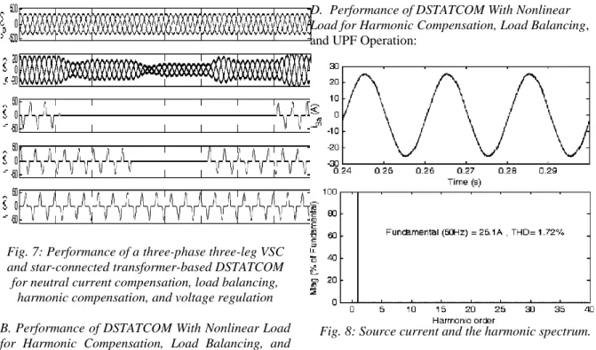
Fig. 7: Performance of a three-phase three-leg VSC and star-connected transformer-based DSTATCOM for neutral current compensation, load balancing,
harmonic compensation, and voltage regulation B. Performance of DSTATCOM With Nonlinear Load for Harmonic Compensation, Load Balancing, and ZVR Operation:
The dynamic performance of the DSTATCOM with nonlinear and unbalanced load is given in Fig. 7. It is observed that the harmonic current is compensated and the source currents are balanced and sinusoidal. At 0.8 s, the load is changed to two-phase load and to single-phase load at 0.9 s. The loads are applied again at 1.0 and 1.1 s, respectively. The source currents are still balanced and sinusoidal even when the load current in a phase is zero. The dc bus voltage of DSTATCOM is maintained at nearly its reference value under all load disturbances.
C. Performance of DSTATCOM With Linear Load for Neutral Current Compensation, Load Balancing, and UPF Operation:
The dynamic performance of the DSTATCOM during linear lagging power-factor-unbalanced load condition At 0.6 s, the load is changed to two-phase load and to single-phase load at 0.7 s. The loads are applied again at 0.8 and 0.9 s, respectively. The PCC voltages (vS ),
source currents (iS ), load currents (iL ), compensator
currents (iC ), source-neutral current (iSn), load-neutral
current (iLn), compensator-neutral current (iCn), dc bus
voltage (vdc), and amplitude of voltage (VS ) at PCC
are also depicted. The reactive power is compensated for power factor correction, and the source currents are balanced and sinusoidal. The source-neutral current is nearly zero and it verifies the proper compensation. It is also observed that the dc bus voltage of DSTATCOM is maintained at the reference value under all load disturbances.
D. Performance of DSTATCOM With Nonlinear Load for Harmonic Compensation, Load Balancing, and UPF Operation:
Fig. 8: Source current and the harmonic spectrum. The source currents are observed as balanced and sinusoidal under all these conditions. At 1.6 s, the load is changed to two-phase load and again to single-phase load at 1.7 s. The loads are applied again at 1.8 and 1.9 s, respectively. The PCC voltages (vS ), source
currents (iS ), load currents (iLa, iLb, iLc), compensator
currents (iC ), source-neutral current (iSn),
compensator-neutral current (iCn), load-neutral current
(iLn), dc bus voltage (vdc), and amplitude of voltage
(VS ) at PCC are also depicted. The dc bus voltage of
DSTATCOM is maintained at the reference value under all load disturbances through proper control. 10–12, respectively. The total harmonic distortion of the source current is 1.72%, whereas that of the load current is 63.50%, and this shows the satisfactory performance of DSTATCOM for harmonic compensation as stipulated by the IEEE-519 standard.
Conclusion:
The performance of a new topology of this paper has been demonstrated for neutral current compensation along with reactive power compensation, harmonic elimination, and load balancing. The T-connected transformer has mitigated the source-neutral current. The voltage regulation and power factor correction modes of operation of the DSTATCOM have been observed and are as expected. The dc bus voltage of the DSTATCOM has been regulated to the reference dc bus voltage under all varying loads. Two single phase transformers are used for the Star-configuration of the transformer to interface with a three-phase four-wire system. The total kilovolt Amperes rating of the Star-connected transformer is lower than a star/delta transformer for a given neutral current compensation. The experimental results on a prototype have verified that the Star-connected transformer has been effective in compensating the zero sequence fundamental and harmonics currents.
A T-connected transformer and Three-leg VSC based DSTATCOM for power quality improvement. In this project two single phase transformers are connected in T-configuration for inter facing to a three-phase four-wire power distribution system. Here in this project two single –phase transformers are required so some winding losses and cost of winding for required values will be more. So if we replace the T-connected transformer with one Three-phase transformer, winding losses will be less, cost of the winding also will be less.so the Star connected transformer also will be useful to compensate the neutral current in the distribution system.
References:
[1] A. Ghosh and G. Ledwich, Power Quality Enhancement using Custom Power Devices, Kluwer Academic Publishers, London,2002. [2] Ewald F. Fuchs and Mohammad A. S. Mausoum,
Power Quality in Power Systems and Electrical Machines, Elsevier Academic Press,London, UK, 2008.
[3] Hurng- Liahng Jou, Jinn- Chang Wu, Kuen- Der Wu, Wen- JungChiang and Yi- Hsun Chen, “Analysis of zig-zag Transformer applying in the three-phase Four- Wire Distribution Power System,”IEEE Trans. Power Delivery, vol. 20, no. 2, pp. 1168- 1173, April2005.
[4] Hurng-Liahng, Kuen- Der Wu, Jinn- Chang Wu and Wen- JungChiang, “A three-phase four- wire power filter comprising a threephasethree-wire active filter and a zig-zag transformer,” IEEETrans. of Power Electronics., vol. 23, No. 1, pp. 252- 259, Jan.2008.
[5] H. L. Jou, K. D. Wu, J. C. Wu, C. H. Li and M. S. Huang, “Novelpower converter topology for three-phase four-wire hybrid powerfilter”, IET Power Electron., vol.1, No.1, pp. 164-173, 2008.
[6] P. Vedelho and G D Marques, “A neutral current electroniccompensator,” in Proc. of IEEE Proceedings in IndustrialElectronics, vol.2, pp.831-836, Aug/Sept 1998.
[7] B. N. Singh, P.Rastgoufard, B.Singh, A.Chandra, and K.A.Haddad, “Design, Simulation and implementation of three pole/four pole topologies for active filters,” in Inst, Electr. Eng. Proc. Electr. Power Appl., Jul. 2004, vol.151, no.4, pp. 467-476.
[8] L. H. Beverly, R. D. Hance, A. L. Kristalinski, and A. T. Visser, “Method and apparatus for reducing the harmonic currents in alternating current distribution networks,” U.S. Patent 5 576 942, Nov. 19, 1996.
[9] H.-L. Jou, J.-C. Wu, K.-D. Wu, W.-J. Chiang, and Y.-H. Chen, “Analysis of zig-zag transformer applying in the three-phase four-wire distribution power system,” IEEE Trans. Power Del., vol. 20, no. 2, pp. 1168–1173, Apr. 2005.
[10]H.-L. Jou, K.-D. Wu, J.-C. Wu, and W.-J. Chiang, “A three-phase four-wire power filter comprising a three-phase three-wire active filter and a zig-zag transformer,” IEEE Trans. Power Electron., vol. 23, no. 1, pp. 252–259, Jan. 2008. [11]H. L. Jou, K. D. Wu, J. C. Wu, C. H. Li, and M.
S. Huang, “Novel power converter topology for three-phase four-wire hybrid power filter,” IET Power Electron., vol. 1, no. 1, pp. 164–173, 2008. [12]H. Fugita and H. Akagi, “Voltage-regulation
performance of a shunt active filter intended for installation on a power distribution system,” IEEE Trans. Power Electron., vol. 22, no. 1, pp. 1046–1053, May 2007.
[13]M. C. Benhabib and S. Saadate, “New control approach for four-wire active power filter based on the use of synchronous reference frame,” Electr. PowerSyst. Res., vol. 73, no. 3, pp. 353– 362, Mar. 2005.
[14]M. I. Milan´alez, “Comparison of control es, E. R. Cadaval, and F. B. Gonz´strategies for shunt active power filters in three-phase four-wire systems,” IEEE Trans. Power Electron., vol. 22, no. 1, pp. 229–236, Jan. 2007.
[15]B. A. Cogbill and J. A. Hetrick, “Analysis of T–T connections of two single phase transformers,” IEEE Trans. Power App. Syst., vol. PAS-87, no. 2, pp. 388–394, Feb. 1968.
[16]IEEE Guide for Applications of Transformer Connections in Three-Phase Distribution Systems, IEEE C57.105-1978 (R2008).
[17]B. Singh, V. Garg, and G. Bhuvaneswari, “A novel T-connected autotransformer-based 18-pulse AC–DC converter for harmonic mitigation in adjustable-speed induction-motor drives,” IEEE Trans. Ind. Electron., vol. 54, no. 5, pp. 2500–2511, Oct. 2007.