04 August 2020
POLITECNICO DI TORINO
Repository ISTITUZIONALE
Network Infrastructures for Highly Distributed Cloud-Computing / Lucrezia, Francesco. - (2018 Apr 16). Original
Network Infrastructures for Highly Distributed Cloud-Computing
Publisher: Published DOI:10.6092/polito/porto/2706032 Terms of use: openAccess Publisher copyright
(Article begins on next page)
This article is made available under terms and conditions as specified in the corresponding bibliographic description in the repository
Availability:
This version is available at: 11583/2706032 since: 2018-04-23T10:40:08Z Politecnico di Torino
Doctoral Dissertation
Doctoral Program in Computer and Control Engineering (29thcycle)
Network Infrastructures for Highly
Distributed Cloud-Computing
By
Francesco Lucrezia
******
Supervisor(s):
Prof. Guido Marchetto
Doctoral Examination Committee:
Prof. Flavio Esposito Prof. Barbara Martini Dr. Domenico Siracusa Dr. Balazs Sonkoly
Politecnico di Torino 2018
Declaration
I hereby declare that, the contents and organization of this dissertation constitute my own original work and does not compromise in any way the rights of third parties, including those relating to the security of personal data.
Francesco Lucrezia 2018
* This dissertation is presented in partial fulfillment of the requirements forPh.D.
To my parents,
my partner in life Cinzia and my newborn son Alessandro
Acknowledgements
Thanks to my supervisor Guido who has been a precious guide in this - sometimes suffered - journey called PhD.
Thanks to Fulvio, my second advisor who has always been capable of giving me the right advises.
Thanks to my family who always supports me, in the good and in the bad. Thanks to all my colleagues and friends.
Thanks,
Abstract
Software-Defined-Network (SDN) is emerging as a solid opportunity for the Net-work Service Providers (NSP) to reduce costs while at the same time providing better and/or new services. The possibility to flexibly manage and configure highly-available and scalable network services through data model abstractions and easy-to-consume APIs is attractive and the adoption of such technologies is gaining momentum. At the same time, NSPs are planning to innovate their infrastruc-tures through a process of network softwarisation and programmability. The SDN paradigm aims at improving the design, configuration, maintenance and service provisioning agility of the network through a centralised software control. This can be easily achievable in local area networks, typical of data-centers, where the benefits of having programmable access to the entire network is not restricted by latency between the network devices and the SDN controller which is reasonably located in the same LAN of the data path nodes. In Wide Area Networks (WAN), instead, a centralised control plane limits the speed of responsiveness in reaction to time-constrained network events due to unavoidable latencies caused by physical distances. Moreover, an end-to-end control shall involve the participation of multiple, domain-specific, controllers: access devices, data-center fabrics and backbone net-works have very different characteristics and their control-plane could hardly coexist in a single centralised entity, unless of very complex solutions which inevitably lead to software bugs, inconsistent states and performance issues.
In recent years, the idea to exploit SDN for WAN infrastructures to connect multiple sites together has spread in both the scientific community and the indus-try. The former has produced interesting results in terms of framework proposals, complexity and performance analysis for network resource allocation schemes and open-source proof of concept prototypes targeting SDN architectures spanning mul-tiple technological and administrative domains. On the other hand, much of the
x
work still remains confined to the academy mainly because based on pure Openflow prototype implementation, networks emulated on a single general-purpose machine or on simulations proving algorithms effectiveness. The industry has made SDN a reality via closed-source systems, running on single administrative domain networks with little if no diversification of access and backbone devices.
In this dissertation we present our contributions to the design and the imple-mentation of SDN architectures for the control plane of WAN infrastructures. In particular, we studied and prototyped two SDN platforms to build a programmable, intent-based, control-plane suitable for the today highly distributed cloud infrastruc-tures. Our main contributions are:(i)an holistic and architectural description of a distributed SDN control-plane for end-end QoS provisioning; we compare the legacy IntServ RSVP protocol with a novel approach for prioritising application-sensitive flows via centralised vantage points. It is based on a peer-to-peer architecture and could so be suitable for the inter-authoritative domains scenario.(ii)An open-source platform based on a two-layer hierarchy of network controllers designed to provision end-to-end connectivity in real networks composed by heterogeneous devices and links within a single authoritative domain. This platform has been integrated in CORD, an open-source project whose goal is to bring data-center economics and cloud agility to the NSP central office infrastructures, combining NFV (Network Function Virtualization), SDN and the elasticity of commodity clouds. Our platform enables the provisioning of connectivity services between multiple CORD sites, up to the customer premises. Thus our system and software contributions in SDN has been combined with a NFV infrastructure for network service automation and orchestration.
Contents
List of Figures xiv
List of Tables xvi
1 Introduction 1
2 ONOS: Open Network Operating System 5
2.1 ONOS Overview . . . 5
2.2 Control vs Configuration . . . 7
3 ICONA: A Peer-to-Peer Approach for Software Defined Wide Area Net-works Using ONOS 10 3.1 Motivation . . . 10
3.2 ICONA Architecture . . . 12
3.2.1 ICONA Provider . . . 13
3.2.2 ICONA Southbound Mechanisms . . . 17
3.3 Evaluation . . . 17
3.3.1 Reaction to Network Events . . . 19
3.3.2 Startup Convergence Interval . . . 22
4 A Proposal for End-to-End QoS Provisioning in Software-Defined
xii Contents 4.1 Motivation . . . 23 4.2 System Workflow . . . 25 4.3 QoS Provisioning . . . 27 4.3.1 General Discussion . . . 27 4.3.2 Comparison with RSVP . . . 29 4.3.3 End-to-End Behaviour . . . 31
4.4 East-West Resource Exchange . . . 34
4.4.1 Pre-Shared Network Parameters and Bandwidth Resource . 35 4.4.2 On-demand Network Parameters and Bandwidth Resource . 36 4.4.3 Inter-Domain Resource Scope . . . 37
4.5 Policy Enforcement . . . 38
4.6 Architecture . . . 39
4.6.1 High-level System Components . . . 39
4.6.2 The Manager Application . . . 40
4.6.3 Routing and Scalability . . . 42
4.7 Algorithm Computation Time Evaluation . . . 42
5 Hierarchical End-to-End Network Control with ONOS 46 5.1 Overview . . . 46
5.2 Architecture . . . 47
5.2.1 Topology Abstraction . . . 48
5.2.2 Service Orchestration . . . 50
5.2.3 The Communication Channel . . . 50
5.2.4 Domain-specific Network Provisioning . . . 52
5.3 Enterprise CORD . . . 53
5.3.1 CORD: Central-Office-Rearchitected-as-a-Datacenter . . . . 53
Contents xiii
6 Related Work 59
7 Conclusion 64
References 67
Appendix A ONOS Driver based on YANG Data Model compiled with
List of Figures
2.1 ONOS distributed architecture . . . 6
2.2 Model-based device drivers implementation via Yang/Netconf . . . 9
3.1 ICONA topology abstraction. . . 14
3.2 Service request accomplished with ICONA. . . 16
3.3 High level view of the ICONA components. . . 18
3.4 Average, maximum and minimum latency to reroute 100 paths in case of link failure for ONOS and ICONA (2, 4 and 8 clusters) . . . 20
3.5 GÉANT pan-European network . . . 21
4.1 Reference scenario . . . 27
4.2 Domain topology abstraction . . . 28
4.3 Driver modules in the controller are the means for device-level configuration of the queues . . . 34
4.4 Two allocation schemes for two layers of the network . . . 35
4.5 Controller’s Main Components . . . 40
List of Figures xv
4.7 Percentage of requests served within a certain amount of time ex-pressed in milliseconds. With a concurrency levelc=100 (Fig. a, c) 1000 thousands requests are processed in less than 1sec. (Fig. a) and in about 3 sec. (Fig. c). With a c=1000, the processing time increases exponentially w.r.t. the total number of served requestsn
(Fig. b, f). With hundreds of nodes (Fig. e, f), even withc=1000 we are in the order of tens of seconds for 1000 requests. The goodness of these results is relative to the type of service and network involved. For example, does a HQ streaming video on-demand for premium customers expect a request rate of thousands of requests per second? Is the QoS applied to all the network nodes along the path or on a
small subset of them? . . . 44
5.1 Bottom-up topology discovery phase. . . 49
5.2 Top down service request elaboration. . . 50
5.3 Optical domain transport network . . . 53
5.4 CORD Infrastructure . . . 54
5.5 ECORD scenario . . . 55
5.6 ECORD topology abstraction . . . 56
List of Tables
3.1 GÉANT network: average, maximum and minimum latency to reroute 100 paths in case of link failure for ONOS and ICONA (2, 4 and 8 clusters) . . . 22 3.2 Amount of time required to obtain the network convergence after
disconnection for ONOS and ICONA . . . 22 4.1 Single-request computation time . . . 43
Chapter 1
Introduction
New IT system models are driven by the composition of software services exposed to consumer entities that can benefit from the functionalities such services export transparently, in the most technology and protocol independent way. Composition of very complex system involves synergies of distributed infrastructures of network, storage and compute elements with the objective of achieving very large scale of provisioning and automation.
In this highly dynamic world of Cloud-Computing and Everything-as-a-Service, Network Service Providers (NSPs) are facing important challenges to keep up with the changing, striving to innovate their network infrastructures at the pace con-tent providers do with their services whose proliferation leverages on high-volume standard servers (e.g., x86-based blades), computing/storage virtualisation and dis-tributed applications running on a massive number of heterogeneous devices. Digital contents are consumed by smart phones and sophisticated terminal stations that continuously evolve together with the applications they host. Interestingly enough, the evolution of the Over-The-Top (OTT) services is mainly happening without the aid of the NSPs, within the best-effort data traffic channel in the access networks. OTT providers are widely exploiting the cloud infrastructure to scale in/out without worrying about the infrastructure itself. Connectivity services spanning Wide-Area-Networks (WANs), metro areas and geographically distributed data-centers, instead, are still mainly statically provisioned. This is due to a variety of reasons: standards, protocols and interoperability heavily impact the adoption of dynamic and automated systems; networking problems are complex in nature and networking solutions are
2 Introduction
strongly constrained by hardware equipment. Moreover, network management and control tools have been always considered matter for device manufacturers, which offer their solution under closed source code and proprietary platforms inevitably leading to vendor lock-ins and degradation in flexibility, freedom, security, rev-enues and accountability which are inherent benefits in the adoption of open-source software.
A huge effort is being placed by the Telcos, followed by device vendors, in supporting and financing large open-source projects dedicated to the control plane of the network infrastructures exploiting SDN and NFV [1–5]. In fact these new technologies have radically changed the concept of network architectures decoupling the control plane from the data packet plane, introducing new ways of exploiting the functionalities of network equipments via virtualisation. This enables the net-work modelling to be dynamic, flexible and scalable, able to guarantee a simpler management and a faster speed of development and deployment of new services and technologies, reducing issues and limitations due to the staticity of hardware components.
Although the early SDN products primarily focus on automation and orches-tration within a data-center, the more mature SDN solutions, such as those from Google and Amazon, are designed to take intercloud federation across WAN and software-defined WAN into consideration ([6]). A common factor of innovation growth of these companies is their ability to potentially exploit the benefits of having programmable access to the entire network stack, from the lowest-level hardware to the highest-level software elements for the control of the east-west (data-center to data-center) traffic; rather than being forced to create compromised solutions based on available insertion points, they can design end-to-end secure and performant solu-tions, by coordinating across the network stack. In this regard, NSPs are in a more disadvantaged position because of vendors, protocols and standards bonds. Many SDN platforms have been conceived and developed by the scientific community, but either they target base platform forapplication development environmentto build network applications on top of it, without providing solutions to actual networking problems (e.g. [7, 8]), or they present a broad overview of SDN platforms for dis-tributed and/or multi domain networks focusing on the distribution mechanisms of the network state in the control plane, taking into account solely the forwarding part via the Openflow protocol, leaving aside the prescriptions to implement real network
3
services on such platforms [9–13]; some proposals focus on theoretical modeling and placement problems for distributed control plane in SDN ([14–18]).
In this context are located the activities of the PhD defining this dissertation. We consider concrete networking problems, specifically the per-flow QoS provisioning and the Carrier-Ethernet virtual circuits provisioning, to present two SDN platforms aimed at overcoming the limitations of a single logically centralised SDN controller when dealing with geographical and heterogeneous networks. The main focus of the studies have been on the architectural perspective and the software design of such platforms. In particular, part of the thesis will cover an SDN platform based on ONOS (Chapter 2), a network controller that targets scalability, high availability, high performance and abstractions to make it easy to create networking apps and services. Thus we leverage on ONOS high availability for the state distribution among a cluster of controller instances. The platform enables:
• A single administrative domain network to be divided into multiple regions piloted by different network controllers to decrease event-to-response delays, increase the overall robustness to geographical network faults and distribute the load among the cluster of network controllers (Chapter 3). An event can be something happening in the data path for which there is a feedback control implemented in ONOS (e.g. port state change, device or link discovery) or something generated in the controller surface, such as a policy update. • The communication with other administrative domains leveraging on an
east-west interface to ensure full control of services and events between domains and enforce configuration policies between domains (Chapters 3, 4).
• Dynamic setup of end-to-end priority paths with guaranteed bandwidth for data packet flows over WANs and/or geographically distributed data-centers and users (Chapter 4). We describe how the flow-based QoS model conceived with RSVP [19] can be revised and implemented in a distributed SDN platform to bring end-to-end QoS provisioning over WAN on a pre-application basis which is still missing in today networks. We present an algorithm for admission control implemented on top of ONOS.
Chapter 5 will focus on the rationale and the insights behind the design and the development of a platform that is part of a wider open-source project: CORD [1];
4 Introduction
it was conceived upon the need of an open-source reference platform for connec-tivity service and bandwidth on-demand, end-to-end control over an heterogeneous network and to enable a unified view/orchestration of the access and transport re-sources. It enables on-demand mobility and migration of services such as VMs and storage between geographically distributed data-centers by unifying intra and inter data-center network control and management. The ambition of the project is to shift much of the concepts embraced by the SDN paradigm from the academic to the industry world, and from the single data-center premise to geographic networks with particular emphasis for dedicated connectivity services for enterprises such as Carrier Ethernet circuits provisioning on-demand. The system is able to drive a network composed of different commercial devices, from whitebox Openflow switches to proprietary Netconf-enabled CPE devices and disaggregated ROADMs. We believe that being able to properly control real physical devices is essential for a meaningful system and software wise contribution to the SDN control-plane infrastructures, because ultimately, it is the hardware that processes and transmits bits over the wire. This is one major contribution and distinction factor from related proposals, to the best of our knowledge, there is no open-source system able and tested to drive a chain of physical devices from the very access customer premises to the backbone optical transport switches. And it can be easily extended to other different domain technologies such su G/MPLS networks. Moreover, being a sub-project of CORD, it is seamlessly integrated with NVF service chaining provided in CORD. In this open-source project we designed and developed the hierarchical platform of network controllers using ONOS [20].
Chapter 2
ONOS: Open Network Operating
System
2.1
ONOS Overview
ONOS (Open Networking Operating System) [7] is a distributed network controller created and maintained by the ONF team [21]. It is an open-source joint community effort with substantial contribution from various partners including AT&T, NEC, Huaweii and Verizon [2]. Most of our contributions have resolved into prototype applications running on it. In this chapter we give a broad description of it and then we will further dig into its architecture in later discussion.
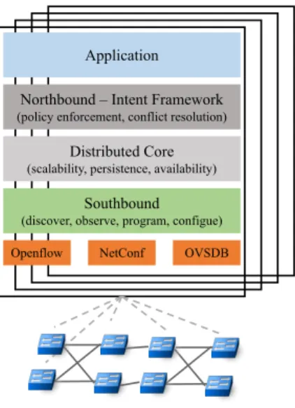
ONOS is an SDN operating system for Service Providers, that is targeting scalability, high availability, high performance and abstractions to make it easy to create apps and services. It implements a distributed architecture using RAFT [22] in which multiple controller instances share multiple distributed data stores with different level of consistency. The entire data plane is managed simultaneously by the whole cluster of instances. However, for each device a single controller instance acts as a master, while the others are ready to step in if a failure occurs. With these mechanisms in place, ONOS achieves scalability and resiliency. Figure 2.1 shows the ONOS internal architecture within a cluster of four instances. ONOS is based on software modules managed by the Apache Karaf suite [23], a set of java OSGi based runtime and applications. It provides a container into which various component can
6 ONOS: Open Network Operating System
Application Northbound – Intent Framework
(policy enforcement, conflict resolution)
Distributed Core
(scalability, persistence, availability)
Southbound
(discover, observe, program, configue) Openflow NetConf OVSDB
Fig. 2.1 ONOS distributed architecture
be deployed, installed, upgraded, started and stopped at runtime, without interfering other components. The southbound modules manage the physical topology, react to network events and program/configure the devices leveraging on different protocols. The distributed core is responsible to maintain coherent information, to elect the master controller for each network portion and to share information with the adjacent layers. In case of a failure in the data path (switch, link or port down), an ONOS instance becomes aware of the event through the southbound modules, computes alternative paths for all the traffic crossing the failed element, and notifies them to the distributed core; then, each master controller configures accordingly its portion of the network. The northbound subsystem offers an abstraction of the network and the interface for applications to interact and program the NOS. Finally, the Application layer offers a container in which third-party applications can be deployed. Applications on top of ONOS can benefit of the Intent Framework. An intent is an abstraction used by applications to specify their high-level desires in form of policies. The ONOS core accepts the intent specifications and translates them into actionable operations on the network environment. These actions are carried out by the intent installation process, such as flow rules being installed on a switch, or optical lambdas (wavelengths) being reserved.
2.2 Control vs Configuration 7
2.2
Control vs Configuration
The basic idea of SDN is to achieve dynamic control over forwarding plane behaviour from a logically centralised vantage point. Telco operators have been doing config-uration and management for quite a long time, from a logical centralised vantage point and for very large network, but the increased demand for performance, agility and reliability due to the advent of cloud-based applications pushed the interest for new automated platform from human time-scales to machine time-scales and with re-duced tolerance for control plane failures. Performance and scalability are important for configuration as well, but the time-scale is different w.r.t to control: configuration and management requires around 1000 operations per day, while control requires around 1000 if not 1000000 operations per second.
Operators want to create and sell customised services with agility and minimal human intervention and create automated ways to instantiate such network services. These services comprise both configuration and control of forwarding devices, (e.g. setting-up lambdas and Openflow rules, provision NFV service chains and steer traffic through them). For this reason operators need a resilient and scalable platform capable of both control and configuration.
ONOS was originally designed to be an SDN platform focusing solely on the control of the forwarding behaviour and for this reason it adopts an API-driven approach that stems from the forwarding rules’ abstractions of the Openflow protocol [24]. Before ONOS, since 2008, multiple controllers were developed with this approach: Beacon [25], Floodlight[26], NOX [27], POX [28] and Ryu [29]. Each controller implemented Openflow as the sole southbound protocol towards the packet forwarding function, and provided access to its control plane functions through northbound REST APIs. Over the years, ONOS has introduced the support for other important protocols such as Netconf and Restconf to add configuration capabilities. ONOS is an API-driven platform because the control abstractions and APIs are semi-fixed, borne out of following the Openflow standard, while configuration abstractions are harder to fix, though standards exist, vendors want to expose their unique features (this explains the explosion of SNMP MIB variables). The pros of the API-driven approach are:
8 ONOS: Open Network Operating System
• The platform is not tied to a closed set of protocols: device drivers can use YANG/NETCONF, SNMP, REST, Openflow and any other to interact with physical devices.
• Applications portability and stable evolution is facilitated. While the cons of are:
• Limit access to new or differentiating device features (unless API is sufficiently open-eneded).
• Enhancements and new features require development resources.
A pure configuration and management platform (see OpenDaylight [8]) would adopt the model-driven approach instead. It consists of a framework based on consistent relationships between (different) models, standardised mappings and patterns that enable model generation and, by extension, code/API generation from models. This generalisation can overlay any specific modelling language although YANG has emerged as the data modelling language for the networking domain. The model driven approach is being increasingly used in the networking domain to describe the functionality of network devices, services, policies and network APIs [30]. Here pros and cons are listed together given their intertwined nature:
• Code-generation avoids manual boilerplate code. Consideration must be given to versioning and to the impact of a model change on the (re)generated API. • Applications have access to nuanced features, not limited by fixed APIs and
they are presented with a fluid surface on the platform. But this implies that applications must be model-aware, that is, they must know the model semantics. This has a strong impact on application portability.
• Enhancements require fewer development resources since much code is auto generated by the models.
The ONOS releases used in our prototypes, 1.9.0 and 1.10.0, adopt an hybrid approach that is a combination of, and a compromise of, the stability given by the semi-fixed APIs used by the NB applications and the elasticity and rich capabilities
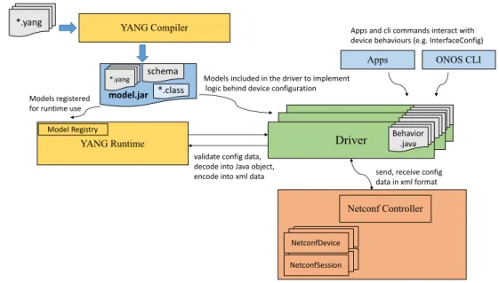
2.2 Control vs Configuration 9 Netconf Controller NetconfDevice NetconfSession YANG Compiler Driver *.yang YANG Runtime Behavior .java
Driver Behavior.java
Driver Behavior.java
model.jar
schema *.yang
*.class
send, receive config data in xml format validate config data,
decode into Java object, encode into xml data Model Registry
Models included in the driver to implement logic behind device configuration Models registered
for runtime use
Apps ONOS CLI
Apps and cli commands interact with device behaviours (e.g. InterfaceConfig)
Fig. 2.2 Model-based device drivers implementation via Yang/Netconf
enabled by YANG/Netconf within the device drivers (Fig. 2.2). Micro-APIs abstract-ing many facets of configuration are expressed in ONOS by extendabstract-ing the Behaviour interface to implement effectively an API per feature (e.g. VXLAN, VLAN, Queues configuration). The implementation encapsulates specific logic and code of the exported capability and within it one can use whatever modelling language (YAML, YANG, SNMP schema etc.) to define semantics and syntax for interacting with the device. Apps and other ONOS subsystems instead are completely independent of such modelling languages and refers to the device capability through such Behaviour abstractions. A collection of behaviours describes the capabilities of a device in ONOS and they are accessible via class projections and casting, while macro APIs remain unchanged (stable) to the northbound applications.
In Chapter 4 we make use of the driver subsystem to implement the logic behind the QoS configuration of the virtual switch OpenVSwitch [31]. In Chapter 5 we use multiple ONOS drivers to control and configure the data path nodes. One of these devices is entirely described via YANG models. The drivers for the Openflow-enabled switches instead are implemented after the ONOS core APIs written in Java. The rest of our system contributions to ONOS touches the application, the core and the provider layers which are device agnostic.
Chapter 3
ICONA: A Peer-to-Peer Approach
for Software Defined Wide Area
Networks Using ONOS
Part of the work described in this chapter has been published in [32]
3.1
Motivation
As mentioned in the introduction, WAN networks are composed by a huge number of distributed network devices and terminal stations. Reliability, scalability and avail-ability are among the major elements of attention expressed by Service and Cloud Providers. Existing deployments show that standard IP/MPLS networks natively offer fast recovery in case of failures. Their main limitation lies in the complexity of the distributed control plane, implemented in the forwarding devices. IP/MPLS networks fall short when it comes to designing and implementing new services that require changes to the distributed control protocols and service logic.
The SDN architecture, that splits data and control planes, simplifies and speeds up the introduction of new services, by moving the intelligence and most of network state from the physical devices to a logically centralised Network Operating System (NOS), also known as controller, in charge of all the forwarding decisions. It is also
3.1 Motivation 11
clear, as described in the work of Heller et al. [5], that even if a single controller may suffice to guarantee round-trip latencies on the scale of a typical mesh restora-tion delays (200 msec), this is not enough for all network topologies. Furthermore, ensuring an adequate level of fault tolerance (i.e., avoiding excessive packet loss and session termination) can be guaranteed only if controllers are spaced apart in different locations of the network. A logical step towards robustness in SDN is to distribute the load of the control plane between entities, each taking care of a portion of the entire geographical network and each providing an east-west communication interface to enable programmability of the entire network. To guarantee the proper level of redundancy in the control plane, several distributed NOS architectures have been proposed in the last years: ONIX [33], Kandoo [13], HyperFlow [9] to name a few. Mainly, these architectures fall into two categories:(i)hierarchy of controllers and(ii)peer-to-peer interconnections between controllers. While the former gives adequate scalability for resources under the control of the same domain, the latter offers more benefits in case of a multi administrative domain solution, removing a top-level entity, possibly managed by a third party, controlling the interconnections between networks belonging to different providers.
In the ONOS architecture, a cluster of controllers shares a logically centralised network view: network resources are partitioned and controlled by different ONOS instances in the cluster. Resilience to faults is guaranteed by design, with automatic traffic rerouting in case of node or link failure. However, despite the distributed archi-tecture, ONOS is designed to be placed in a single geographical location, because its distributed architecture requires negligible communication delays between instances. Given this consideration, we engineered an open-source ONOS application called ICONA (Inter Cluster Onos Network Application). ICONA is designed to work in a single administrative WAN network scenario, increasing the robustness to network faults by redounding ONOS clusters in several geographical locations and decreasing event-to-response delays, as well as in a multi administrative domain scenario. To better support the latter use-case, ICONA is based on a peer-to-peer architecture, and implements configuration policies between clusters (i.e., domains belonging to different owners), that ensure the full control of services and events between domains.
12 ICONA: A p2p Approach for SD-WANs Using ONOS
3.2
ICONA Architecture
ICONA is a new southbound ONOSproviderthat offers an east-west interface and a powerful abstraction layer to allow a single ONOS cluster to be interconnected with several other clusters, both in the same and in different administrative domains.
Providersin ONOS are standalone ONOS applications based on OSGi components
that can be dynamically activated and deactivated at runtime. The main purpose of providersis to abstract the configuration, control and management operations of a specific family of devices (e.g. OpenFlow, SNMP, Netconf, etc.). ONOS interacts with the underlying network with the help of these components. Being a provider, ICONA is completely transparent to the ONOS core systems and to other applications, thus offering the same functionalities of ONOS, but extended to a geographically distributed environment, including multiple administrative domains. From an application perspective, all the features offered by ONOS are then available in an multi administrative domain composed of several ICONA clusters. The main architectural goals of ICONA are to:
• Enable east-west communication between ONOS clusters. In a single-domain, this implies partitioning the Service Providers network into several geograph-ical regions, each one managed by a different cluster of ONOS instances. The network architect can select the number of clusters and their geograph-ical dimension depending on requirements (e.g., leveraging on some of the tools being suggested within the aforementioned work [5]), without losing any features offered by ONOS, neither worsening the system performance. In a multi-domain scenario, several ONOS clusters, belonging to different administrative domains, can exchange network services based on respective policies and network abstractions.
• Provide an abstraction to ONOS, able to:(i)abstract and communicate exter-nal topologies (i.e., devices, links and ports not directly managed by the local cluster),(ii)configure these external devices from local applications, leverag-ing on the Intent Framework and(iii)enforcing policies between clusters. Clusters, policies and topology abstractions can be easily injected in ICONA through the ONOS configuration service. ICONA extrapolates the local topology from the ONOS core, abstracts it based on the configuration and finally exposes it to
3.2 ICONA Architecture 13
remote clusters; likewise, it receives the external topologies from the remote clusters and notifies them to ONOS. In case of a multi domains, this external topology is exposed as a single big switch. Moreover, it takes care of reporting relevant updates to the remote clusters about changes affecting the abstracted topology by listening to events reported by the ONOS subsystems (e.g., devices, links, ports and edge hosts). The east-west communication between clusters is not bounded to a single peer-to-peer mechanism, but it allows different implementations, leveraging on the ICONA Southbound Interface (ISBI).
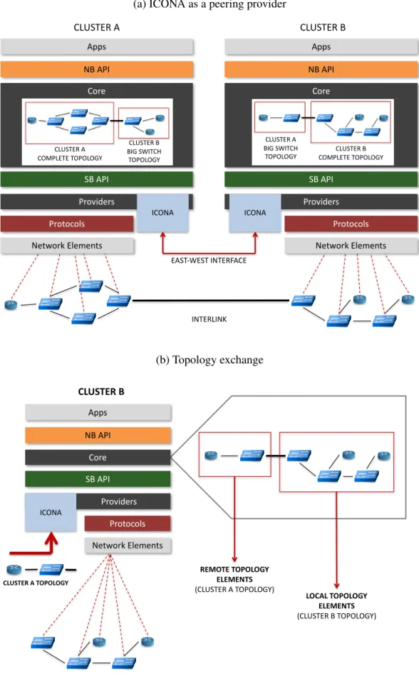
Figure 3.1a depicts two clusters, A and B, sharing their topologies through ICONA. In Figure 3.1b,cluster Aexposes its 4 switches topology as a single big switch, that is abstracted and communicated to the local ONOS core by the ICONA provider ofcluster B.
The communication between clusters relies on the ISBI interface, that can be implemented by different mechanisms. To make ICONA as flexible as possible, its structure is vertically split in two logical layers:
• the ICONA Provider which contains the main logic and lays between the ONOS core and the ISBIs.
• multiple ISBI drivers, each one tied to a specific for a communication mecha-nism. For each remote cluster, it’s possible to specify a different mechanism, thus allowing several ISBI implementations to be used simultaneously. This architecture allows to integrate several communication mechanisms, just by implementing the ISBI logic, without any modifications in the ICONA provider.
3.2.1
ICONA Provider
The provider contains the main logic behind ICONA, and performs various func-tionalities. As aTopology Manager(see 3.2.1), it builds an abstraction of the local topology to be exposed to remote clusters. Currently ICONA supports two topology abstractions: BigSwitch(single switch representing the entire network with edge ports) andFullMesh(network topology in which there is a direct link between all pairs of edge nodes). While the former shrinks the entire topology in a single switch, the latter builds a full virtual mesh topology between all the edge switches (e.g.
14 ICONA: A p2p Approach for SD-WANs Using ONOS
(a) ICONA as a peering provider
Apps NB API Core SB API Providers Protocols Network Elements ICONA Apps NB API Core SB API Providers Protocols Network Elements ICONA CLUSTER A CLUSTER B INTERLINK CLUSTER A COMPLETE TOPOLOGY CLUSTER B BIG SWITCH TOPOLOGY CLUSTER A BIG SWITCH
TOPOLOGY COMPLETE TOPOLOGYCLUSTER B
EAST-WEST INTERFACE (b) Topology exchange Apps NB API Core SB API Providers Protocols Network Elements ICONA CLUSTER B CLUSTER A TOPOLOGY REMOTE TOPOLOGY ELEMENTS (CLUSTER A TOPOLOGY) LOCAL TOPOLOGY ELEMENTS (CLUSTER B TOPOLOGY)
3.2 ICONA Architecture 15
the ones with edge ports) of the network. The provider, after receiveing remote topologies from the southbound mechanisms, notifies them to the local ONOS core, and reacts to network events which could reflect a change in the topology exposed to/from the remotes. As aService Manager(see 3.2.1), it manages service requests coming from the local applications to remote clusters and vice versa. Finally, as a
Policy Manager(see 3.2.1), it enforces configuration policies between clusters. The
next sections detail the features offered by the three provider modules, depicted in Figure 3.3.
Topology Manager
The Topology Manager (TM) is responsible to(i)analyse the remote topologies and install them in ONOS with the relevant metric and annotations, and(ii) reacts to network events, both local and remote. Each TM shares with the other clusters an abstraction of the local topology, that may vary from cluster to cluster, based on the configuration. The topology is composed of:
• Inter-links (IL): links belonging to different ONOS clusters. Each IL is pro-vided trough the ONOS configuration subsystem and it’s tagged by some metrics, such as the link delay, available bandwidth and number of flows crossing the link.
• Virtual devices and intra-links: links within the local cluster/domain.
• End-points (EP): interconnection ports between the customer’s gateway router/switch and the ONOS network.
Service Manager
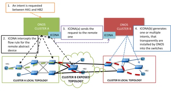
The Service Manager (SM) is the ICONA component, that provides inter-cluster path computation whenever a northbound application, on-top of ONOS, requires connectivity between two or more EPs crossing multiple clusters. The SM intercepts an intent requests from the ONOS core targeting one or more virtual devices of the remote topology and sends it to the target remote cluster (Fig. 3.2). The recipient translates the remote intent request into a local intent request and submits it to the ONOS Core. The translation consists in resolving the mapping between the abstract
16 ICONA: A p2p Approach for SD-WANs Using ONOS ONOS CLUSTER A ICONA ONOS CLUSTER B ICONA HA1 HB2
CLUSTER A LOCAL TOPOLOGY CLUSTER B EXPOSEDTOPOLOGY
HB2
CLUSTER B LOCAL TOPOLOGY 1. An intent is requested
between HA1 and HB2
2. ICONA intercepts the flow rule for the remote abstract device
3. ICONA(a) sends the request to the remote one 4. ICONA(b) generates one or multiple intents, that transparently are installed by ONOS into the switches
13
Fig. 3.2 Service request accomplished with ICONA.
ingress and egress points of the original request into local ingress and egress points of the underlying network. The evaluation on the feasibility of the intent installation is also performed, both in terms of policy and capabilities. If the request is accepted, the SM waits for the ONOS core to accomplish the task of installing the intent and then notifies the requester about the outcome.
Policy Manager
A multi administrative domain scenario is characterized by the presence of networks under control of different authorities. Usually, the mutual trust between these domains is limited to specific agreements, which identify a list of constraints to be applied at the edge of the network. To support such use-case, ICONA is policy-oriented and enforces, through configuration, the compliance to those agreements. Currently ICONA allows to set at runtime several parameters, such as(i)the external peering clusters information,(ii)the topology abstraction exposed to each domain,
3.3 Evaluation 17
(v)the ILs and their metrics (i.e., bandwidth, delay and type),(vi)the preferred path for specific classes of traffic (based on L2 and L3 fields). However, we are currently analysing the common design patterns of BGP policies, that are typically used by ISPs [34], to implement innovative policy mechanisms in the future releases.
3.2.2
ICONA Southbound Mechanisms
A southbound mechanism is an implementation of the communication system be-tween clusters (Fig. 3.3). Basically, it’s a software component in charge of translating the provider’s requests into protocol-specific, network operations and the remote clusters messages into abstracted notifications via the ISBI. This component per-forms the exchange of the information with message encoding and decoding, and does not retain any system state except the status of the remote clusters. Currently ICONA supports two different mechanisms:
• BGP: an extension of the BGP protocol with a new Type-Length-Value (TLV) field to offload the communication system to an external router (e.g. Quagga based) and to use BGP as a pure transport protocol for data exchange.
• REST: a REST client/server peer-to-peer architecture has been implemented between clusters. The client is in charge of sending local topology elements and to request service installation, while the server is responsible to receive remote topology elements and service requests from the other clusters. We implemented a distributed architecture, in which every ICONA instance is responsible to interconnect the local cluster with a set of remote clusters and the communication is balanced among multiple end-points providing resiliency.
3.3
Evaluation
The purpose of the experimental tests described in this section is to compare ICONA with a standard ONOS setup, and evaluate the performances of the two solutions in an emulated environment. It is important to highlight that these evaluation has been achieved with a preliminary version of ICONA, working on an old ONOS version (Blackbird release). For these reasons, the results presented in this section should
18 ICONA: A p2p Approach for SD-WANs Using ONOS PROVIDER Southbound Mechanisms RESTCHANNEL BGPCHANNEL Topology Manager Service Manager Policy Manager BGP REST … Southbound Interface CLUSTER A PROVIDER Southbound Mechanisms Topology Manager Service Manager Policy Manager BGP REST … Southbound Interface PROVIDER Southbound Mechanisms Topology Manager Service Manager Policy Manager BGP REST … Southbound Interface CLUSTER B CLUSTER C
3.3 Evaluation 19
not be considered as benchmark, but they can offer a comparison between the fully centralized solution versus the peer-to-peer architecture offered by ICONA.
The control plane is composed of several virtual machines, each configured to use 4 Intel Core i7-2600 CPUs @ 3.40GHz and 8GB of RAM. For the ONOS tests we used 8 instances, while with ICONA we created 2, 4 and 8 clusters, respectively with 8, 5 and 3 instances each. The data plane is emulated by Mininet [35] and Netem [36]: the former creates and manages the network based on OpenFlow 1.3, while the latter emulates the properties of wide area networks, introducing variable delays, throughput and packet loss. Both solutions (ONOS and ICONA) have been tested on top of “grid” networks and of the GÉANT [37] topology.
3.3.1
Reaction to Network Events
Grid network
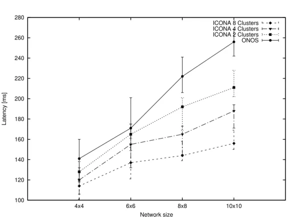
The first measured performance metric is the overall latency of the system for updating the network state in response to events; examples include rerouting traffic in response to link failure or moving traffic in response to congestion. To evaluate how the system performs when the forwarding plane scales-out, few standard grid topologies (from 4*4 to 10*10) have been chosen, with a fixed link delay of 5ms (one-way) and the latency needed to reroute a certain number of installed paths when an inter-cluster link fails is compared between ONOS and ICONA with various clustering settings.
The total latency is defined as the amount of time that ONOS or ICONA requires to react to the failure. It is computed as the sum of: (i)the amount of time taken by the OpenFlow messages (PORT_STATUS andFLOW_MOD) to traverse the control network,(ii)the alternative path computation,(iii)the installation of new flows in the network devices and(iv)the deletion of the pre-existing flows. In particular, we have been running several simulations by installing 103paths in the network and then causing failure of an inter-cluster link carrying al least 102flows.
Figure 3.4 shows the latency (avg, min, max) required for the different case to execute the four tasks previously mentioned. Each test has been repeated 103 times. Despite the same mechanism used by ICONA to compute and install the new paths, the difference is mainly due to the following reasons: (i)each ICONA cluster
20 ICONA: A p2p Approach for SD-WANs Using ONOS 100 120 140 160 180 200 220 240 260 280 4x4 6x6 8x8 10x10 Latency [ms] Network size ICONA 8 Clusters ICONA 4 Clusters ICONA 2 Clusters ONOS
Fig. 3.4 Average, maximum and minimum latency to reroute 100 paths in case of link failure for ONOS and ICONA (2, 4 and 8 clusters)
3.3 Evaluation 21
Fig. 3.5 GÉANT pan-European network
is closer to the devices, thus reducing the amount of time required for OpenFlow messages to cross the control channel and(ii)the ICONA clusters are smaller, with fewer links and devices, thus decreasing the time used for computation and the overall numbers of flows to be installed and removed from the data plane.
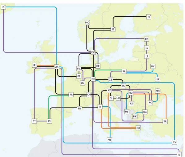
GEANT network
The same metrics have been evaluated on the GÉANT topology (see Figure 3.5). Circuits have various one-way delays (from 10 to 50ms) and throughputs (from 1 to 100Gbps).
Table 3.1 depicts similar results as the previous test. While the GÉANT network is smaller than the grid topology, with 41 switches and 58 bi-directional links, the
22
ICONA: A Peer-to-Peer Approach for Software Defined Wide Area Networks Using ONOS
Control plane Avg latency [ms] Min latency [ms] Max latency [ms]
ONOS 297 284 308
ICONA2 272 261 296
ICONA4 246 232 257
ICONA8 221 199 243
Table 3.1 GÉANT network: average, maximum and minimum latency to reroute 100 paths in case of link failure for ONOS and ICONA (2, 4 and 8 clusters)
higher delay in the data plane adds an additional time before convergence to a stable state.
3.3.2
Startup Convergence Interval
This second experiment measures the overall amount of time required for both solutions to re-converge after a complete disconnection between the control and data planes. The tests have been performed over the GÉANT topology, and replicated 103times. Table 3.2 shows the average, maximum and minimum values in seconds.
Control plane Average Time [s] Minimum Time [s] Maximum Time [s]
ONOS 6,98 6,95 7,06
ICONA 6,96 6,88 7,02
Table 3.2 Amount of time required to obtain the network convergence after disconnection for ONOS and ICONA
The result shows that ICONA and ONOS require comparable time intervals to return to a stable state, in case of a complete shutdown or a failure of the control plane.
In the next chapter we are going to describe a QoS framework architecture on top of ONOS which exploit the functionalities provided by ICONA for the inter domain control over WAN.
Chapter 4
A Proposal for End-to-End QoS
Provisioning in Software-Defined
Networks
Part of the work described in this chapter has been published in [38].
4.1
Motivation
Cloud-based, real-time applications are likely to spread over the next years with the advent of IoT and smart mobility systems. Recently, a new plethora of applications requiring a RTT delay of around 1ms have been grouped under the hat of tactile-Internet applications: a tactile sensor reads information and a connected system reacts with actuators seen by a human within 1 ms [39]. Although we are still far from achieving end-to-end RTT of around 1ms with wireless communications, ISPs need to be ready to re-architect their software control-plane in order to fully exploit the enormous potentials offered by their infrastructures.
Current adoption of distributed control algorithms forces the use of the same signaling protocol (e.g. RSVP, BGP-LS) in all the data-path nodes, not taking into account the resistances inevitably present between device vendors and between administrative domains. For this reason the Service-Level-Agreements (SLAs)
be-24 A Proposal for End-to-End QoS Provisioning in Software-Defined Networks
tween a service provider and its customers or between providers are still mainly static. Moreover, the experience has shown that the scalability issue of the core network in maintaining per-flow state for resource reservation in each node along a path prevented the diffusion of RSVP and integrated services in general. As discussed in [40], per-flow service treatment does not scale in the Internet core; backbone routers must be fast and only anaggregate behaviouris feasible. Instead, it is important to enable such treatment at the edge of the network where mass of users enjoying a mixture of heterogeneous applications share indistinctly the same portion of the network as in the case of cellular access networks; performance degradation is likely to happen in the access links where an increasing number of traffic sources and sinks can introduce a significant amount of queueing delay. Given these considerations, we believe that an hybrid combination of flow-based and class-based traffic treatment, respectively at the edge and in the core of the network, could enable guaranteed services for current and future real-time applications. Since these applications could have terminals deployed all around the globe, the end-to-end provisioning will have to span a chain of administrative domains, requiring an east-west communication interface to convey data that vary from classic inter-domain routing information exchanged via BGP. If we make the assumption that QoS requirements requested by the customer applications are satisfied in the core network, at least for what concerns a delay bound, and up to a maximum bandwidth allocation, then we can think to overlay an integrated service scheme on top of the current deployments where class-based treatment is applied, as long as the resource admission control system is able to map the dynamic service requests to the statically allocated resources in the core.
In this Chapter we present the design and a prototype implementation, partially based on ICONA (Chapter 3), of a control-plane network application for provision-ing dynamic end-to-end QoS profiles to end-user applications. Our proposal is a signaling scheme for path reservation and configuration whose implementation does not require the involved data-path devices to be bound to a single control protocol. The aim is to solve the interoperability problem in provisioning end-to-end guaran-teed services, in a multi-vendor, multi-technology and multi-domain environment by exploiting current software technologies advances; in particular, the decoupling between functional intents and the way they are accomplished is crucial.
4.2 System Workflow 25
The next sections are organised as follows: Section 4.2 gives a high level descrip-tion of the complete system workflow, the first part of Secdescrip-tion 4.3 is dedicated to a general introduction to the QoS and to the Internet technologies adopted to achieve it. Here is where the most of the related works are considered. Then in Section 4.3.2 the critical issues of RSVP are presented and in Section 4.3.3 the end-to-end behaviour of the QoS system is taken into account. In Section 4.4 we discuss the communication interface between clusters or domains of networks required to achieve the end-to-end provisioning, while in Section 4.5 a brief contextualisation of our work into a policy management system is presented. Section 4.6 contains the details of our prototype implementation while Section 4.7 presents some benchmark results on the service request computation time.
4.2
System Workflow
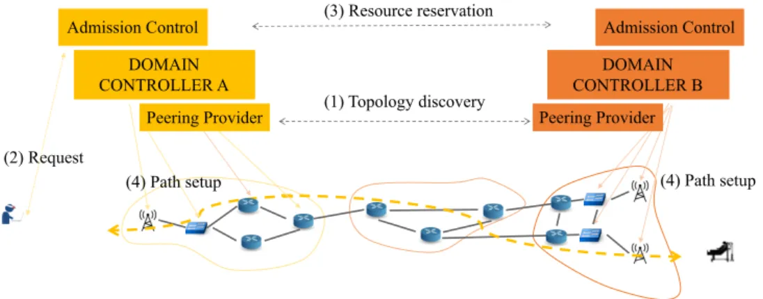
The overall process is activated upon the occurrence of an event triggering the dis-patch of a request sent by an Over-The-Top (OTT) application. The request contains a user authentication token, an application identifier, information about an endpoint to contact together with additional flow specifications, and a QoS profile containing delay and bandwidth requirements, plus an amount of time (or an estimate of it) for which the profile is required. A previous agreement between the user and the network operator is made in order to convey to a traffic plan based on its dynamism, amount of data, QoS parameters, number of requests and possibly other parameters. The request is sent to a manager application running on top of the local domain controller that is listening for incoming connections from registered users. The authentication token, previously generated in a hand-shake phase is verified and the content of the payload is parsed and elaborated as follows.
The endpoint information, either a destination address (L2 or L3, depending on the use-case) or the hostname of the machine to be contacted, is used as look-up key to get the collection of candidate paths existing between the end terminals of the user application. Then anadmission controlroutine runs to check the availability of a suitable path where resources are to be reserved for the subject QoS profile. Once a path is selected, the network application has to instruct the core controller to setup a priority flow between the endpoints of the user application; for the sake of simplicity,
26 A Proposal for End-to-End QoS Provisioning in Software-Defined Networks
we will refer to point-to-point paths, although the solution is equally applicable to paths with multiple destinations ( > 2).
It may be necessary to establish connectivity between the endpoints, other than traffic control’s rules. For example, in a pure Openflow network where none of the routing protocol suite runs in the data-path devices, the controller would prescribe a set of flow rules containing forwarding instructions, together with QoS constraints. If forwarding rules have been previously installed on the data-path devices, then only traffic classification and shaping is to be done through device-specific configurations.
To setup a priority flow, the manager application issues the setup of custom queues in the devices along the selected path and sends an intent request to the controller’s core with the specification of the target flow. An intent is an abstraction used by the applications to specify their high-level desires in form of policies. The ONOS network controller (Chapter 2), used in our prototype implementation, is the first open-source controller that provide such feature to its applications. The intent is then split by the core into device-specific flow rule requests dispatched to the proper software drivers of the underlying devices. Queues are also configured by means of device-specific drivers. Unfortunately the ONOSIntent subsystemdoes not support the configuration of queues and its southbound level yet, and so we had to implement the configuration in our application.
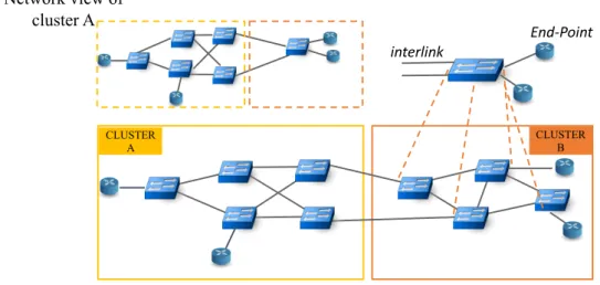
As mentioned before, the endpoints can normally span multiple domains and, clearly, each domain has to take care of its portion of the network. A key point of the system is the topology abstraction (Figure 4.2): all forwarding devices of the local domain are exposed to the controller with the same abstraction model, as is an entire remote domain topology, viewed as a single device (a big switch) whose ports are connected to terminal endpoints or to other domain topologies. When the endpoint of the application requesting a priority path resides on a different domain, the admission control routine recognises the presence of a virtual device associated to the remote domain and as a consequence queries the network manager application of the remote domain in order to establish an end-to-end resource reservation along the path between the endpoints (Figure 4.1). Once the process converges, the domain controllers can simultaneously setup the path in their own portion of the network,
4.3 QoS Provisioning 27 (2) Request (1) Topology discovery (4) Path setup (3) Resource reservation DOMAIN CONTROLLER A Peering Provider Admission Control (4) Path setup DOMAIN CONTROLLER B Peering Provider Admission Control
Fig. 4.1 Reference scenario
the manager application that received the original request sends a response back to the user application that can start sending priority data over the network.
4.3
QoS Provisioning
4.3.1
General Discussion
QoS is introduced in packet-switched networks in order to apply a special treatment to specific data packet flows. At the device level, QoS is achieved through traffic classification, shaping, and scheduling at the egress ports; at the ingress ports packets are filtered for policing. Classification determines which treatment each data packet has to undergo, shaping is used to control customer input data rate to conform to the SLAs, while scheduling affects delay and throughput of the data packet flows. Given conformance to a SLA, scheduling at the network interfaces is the lowest level operation gearing QoS provisioning, also known asservice discipline.
At the path level, QoS is achieved through resource reservation over the whole set of nodes along the path. The reservation must be secured end-to-end and the resource allocation in one node must be consistent with the others along the path. A path selection with the end-to-end delay constraint is subject to inaccurate information
28 A Proposal for End-to-End QoS Provisioning in Software-Defined Networks 10 End-Point interlink CLUSTER A CLUSTER B Network view of cluster A
Fig. 4.2 Domain topology abstraction
due to the dynamic nature of the delay and hence subject to theoretical intractability ([41] [42]). However, end-to-end delay and delay jitter bounds have been computed by means of network calculus applied to queueing systems modelling the networks ([43–45]). Academic and industrial communities have been very active in the last decades in investigating network models and algorithms to solve theQoS routing
problem, also known as themulti-constrained path computationproblem ([46–52]). In [40] they cover all the important components of the QoS provisioning in Internet as it has been conceived in the last decades: integrated services, RSVP ([19, 53]), Diff-Serv [54], Multi Protocol Label Switching (MPLS [55]) and constraint-based routing.
Today network operators employ MPLS mainly for layer 2 and Layer 3 Virtual-Private-Network (VPN) services ([56]), while constrain-based routing for Traffic Engineering (TE) operations is complex to achieve in a complete distributed control-plane. Moreover, TE is not useful in presence of congestion. This happens at the bottleneck links that typically reside in the last mile towards the customers. DiffServ model within a single AS is employed by ISPs for class-based treatment of the data packets; but the validity of the Type of Service (ToS) field in the packet IP header may lose completely meaning when traversing multiple administrative domains. In other words, within a single administrative domain the class-based QoS provisioning is theoretically easy to achieve and technology is not the hurdle, while policy and economic factors have the major impact on the fate of the QoS provisioning in the
4.3 QoS Provisioning 29
multi-domain scenario. IntService and the RSVP signaling protocol instead did not take off even within the single administrative domain. RSVP is used for labels distri-bution in G/MPLS but it failed in its primordial intent. In order to accomplish the process described in Section 4.2 an end-to-end guaranteed service must be provided. In the next section we discuss the critical issues of RSVP and in what our proposal differs from it.
4.3.2
Comparison with RSVP
Path Computation and Routing. RSVP uses a combination of Constrained Shrotest Path First (CSPF) algorithm and Explicit Route Objects (EROs) to determine how reserved traffic and signaling messages are routed over the network; RSVP is a distributed signaling protocol and it needs routing to work. EROs are a mean to explicit indicate some nodes that must belong to the reserved path; in order to force a specific path through a set of nodes you should enter and configure each node with specific EROs instructions. If the total bandwidth reservation exceeds the available bandwidth specified across the link for a particular path segment, the path must be recomputed through another route. If no segments can support the bandwidth reservation, path setup fails and the RSVP session is not established.
In our solution the path computation is independent from the routing proto-col. Different routing and forwarding scheme can be used to build the path in the underlying network: flow-rules, labels, tunnels. But no routing of the signaling scheme is needed; centralised path computation is clearly much faster and protocol-independent. The controller only needs the view of the topology as a connected graph. To force the reservation in a specific path, you can directly reserve resources and install forwarding rules into the proper devices at once. The candidate paths are collected from the store and a suitable one is found before injecting resource reservation rules into the network. This occurs in the centralised controller within a single software process.
RSVP is simplex. In RSVP the reservation process is applied in a single direc-tion of the path. To have full duplex reservadirec-tion, the number of operadirec-tions and the
30 A Proposal for End-to-End QoS Provisioning in Software-Defined Networks
messages exchanged are doubled.
In a centralised network controller, you can equally provide simplex or duplex reservation via a single software entity.
Admission and Policy Control. RSVP Admission and policy control is applied to each node. So RSVP implementation must be integrated with each node’s traffic and policy control module, thus increasing the chance of interoperability. RSVP must provide QoS service characterisation within opaque objects parsed by each network node.
In our proposal the QoS service characterisation is completely decoupled by the signaling protocol/scheme and must be embedded only into the front-end APIs consumed by the customer applications. The admission and policy control is applied only once, in each domain, in the central controller. An RPC-based mechanism is used for configuring the traffic control module given the possibility to fulfil the request. Our prototype relies on ONOS. ONOS provides common abstracted be-haviours for traffic selection and treatments that are translated into device-specific rules.
First speaker. RSVP session initiator is the inbound router running RSVP in conjuction with other protocols (e.g. MPLS or GMPLS in case of label distribution). If RSVP is embedded in a host application, then the first network node should speak RSVP, otherwise a tunnel between the application and the first RSVP-capable device shall be created thus increasing the number of operation required for RSVP signaling to work.
In the presented solution the session initiator is a user application featured with proper APIs for contacting the controller. The idea is to keep the API consumer implementation as simple as a REST client that has the capability to create, remove, update and delete a priority path. Such client would be provided for different soft-ware environments.
4.3 QoS Provisioning 31
Scalability. As per [57], the scaling problems of RSVP are linked to the resource requirements (in terms of processing and memory) of running RSVP. The resource requirements increase proportionally with the number of sessions. Each session requires the generation, transmission, reception and processing of RSVP Path and Resv messages per refresh period. Supporting a large number of sessions, and the corresponding volume of refresh messages, presents a scaling problem.
A centralised control plane presents the same scalability issues concerning the state maintenance of an increasing number of sessions in the data-path nodes. But it only matters the traffic control and flow rules, while processing and singnaling overhead are significantly lowered.
Complexity. Finally, and maybe the most relevant obstacle to success, RSVP is complex because it was designed with IP multicast in mind, intermediate nodes have to merge resource reservation requests coming from the receiver nodes. Moreover, the basic RSVP reservation model is "one pass": a receiver sends a reservation request upstream, and each node in the path either accepts or rejects the request. This scheme provides no easy way for a receiver to find out the resulting end-to-end service. To solve this issue an enhancement was proposed [58], introducing further complexity in the concretization of RSVP and the integrated services in general.
Orchestrating the data-path nodes from within a central controller avoids the issues related to the exchange of asynchronous signaling messages. The decision process not being distributed decreases the complexity in maintaining a single state of the system.
4.3.3
End-to-End Behaviour
The end-to-end QoS profile model shall follow the one described in the Specification of Guaranteed Quality of Service [59]. As per [59], "the end-to-end behaviour provided by a series of network elements is an assured level of bandwidth that, when used by a policed flow, produces a delay-bounded service with no queueing loss for all conforming datagrams". We invite to refer to the specifications for further clarification about the QoS model taken into account. Each network node must
32 A Proposal for End-to-End QoS Provisioning in Software-Defined Networks
provide a service that matches, with some error bounds, the fluid model ([60, 61]) through the token bucket scheme with paramters(b,r,p), respectively the bucket size, the token rate and the peak rate. The QoS request includes a maximum end-to-end delay bound,dreq, that shall be guaranteed between the application terminals.
In the centralised controller, the link providers are responsible for notifying the presence of links they are provider for and their characteristics (propagation delay, transmission capacity and the maximum transmission unit); these information are stored in the controller database upon discovery of the link itself. Likewise, the device providers in the southbound must export other relevant information, such as the delay error terms representing how the device’s implementation of the guaranteed service deviates from the fluid model in each network interface (theCtotandDtot in the formula 4.2 below).
On a link l with capacitycl, we define a minimum bandwidth reserved to the best effort traffic,Rbel. LetRibe the allocated bandwidth for a flowi. On each link,
the total number of accepted profilesNis subject to:
N : cl≥Rbel+
N
∑
i
Ri (4.1)
The end-to-end delay bound as defined in [59] is:
[(b−M)/R∗(p−R)/(p−r)] + (M+Ctot)/R+Dtot+
∑
ldpl (4.2)
Withr<=p<=R,Mbeing the path Maximum-Transmission-Unit and∑ldpl the
propagation delay sum.
Statement 4.1 imposes that the sum of the allocated bandwidths forNflows must not exceed the capacity of the link. Flows requesting a maximum delay bound are assigned to higher priority queues w.r.t. to the best effort traffic. It is possible to assign the same high priority queue to more distinct flows, as long as statement 4.1 holds. R shall be chosen such thatdreq is greater or equal to the value computed in equation 4.2, provided thatdreq is greater than the fixed delay terms Dtot and
4.3 QoS Provisioning 33
terminals of the customer application; a new queue is created for a new flow if they are satisfied. As mentioned in the previous section, theadmission controlroutine occurs only once per domain (more details in Sec. 4.4), in the central controller. Network elements must export the proper information, while the drivers have to translate a service request into device-specific traffic control rules.
The provisioning of a guaranteed service along a path of several devices and links is possible only through a cross-vendor and cross-technology solution. This leads to the adoption of software driver modules installed into the centralised controller. These drivers converts the protocol-agnostic rules into device-specific instructions and are essential to solve the interoperability problem derived by the presence of devices from multiple vendors and technologies. For example, in a LTE cellular network, the high-level profile is mapped to a standardised QoS Class Identifier (QCI) by the proper software driver; the mapping would be followed by the setup of the packet data network gateway and the mobile station with some scheduling rules applied to the target data flow [62]. The same high-level profile has to be translated into a specific setup on the backhaul that provides the connectivity towards the core network consisting of all the required switches to aggregate the traffic from the access cellular network [63]. These switches could be, for instance, pure Linux devices in which case the driver would execute a remote procedure call configuring the involved interfaces with the well-known commands suitetc qdisc,tc filterandtc classfor setting up the queues. If instead a switch is an Openflow-enabled device,
classificationandprioritycome within the forwarding rules, while the queue con-figuration for theservice disciplinemust be supplied on a separate communication channel, for example, through OVSDB protocol in Open-vSwitch [31] (Fig 4.3). Together with the local domain (or local cluster in the single administrative domain) our framework adds the reflection of such operations into the remote domain (cluster) where the endpoint of the customer application requesting the service resides.
Note that we control the edge devices on each side of the communication while leaving aside the backbone routers where per-flow service treatment does not scale. While rfc-2212 states that all the nodes of a path should take part of the resource reservation process for equation 4.2 to hold, we argue that the dynamic resource reservation at the edge of the network can occur transparently w.r.t. the statically allocated resources of the core where the QoS exists only for classes of traffic,