Systems Analysis, Modeling,
and Simulation
Course Objectives
• Present a brief overview of systems analysis using the methods of systems modeling and systems
simulation.
• Describe the utility of systems analysis, modeling, and simulation in the context of systems engineering.
Course Overview
• Introductory Material
1. Systems Analysis
2. Modeling & Simulation
• Systems Analysis
3. Systems Life Cycles
4. Systems Engineering Role of Systems Analysis 5. Model-Based Systems Engineering
Course Overview
(cont)• Modeling Techniques & Methods
6. Symbolic Models
7. Mathematical Models
8. Integrated Models
9. Systems Simulation
• Modeling Applications
10. Requirements Analysis & Validation 11. Effectiveness Analysis
12. Margin Modeling 13. Risk Analysis
Definitions
• Tool – any implement, instrument, utensil, or program used to enhance human physical or intellectual capabilities to accomplish work
– Example – Excel, Word, Nastran, etc.
• Model – a (virtual) imitation of an object or process
– Example – Geometry, loads, weights, cost, etc.
• Simulation – to execute a model using a tool to
Lesson 1:
Objectives
• Illustrate the Systems Analysis process
What is Analysis?
• Analysis – the breaking down of a whole into it’s
System Hierarchy
Elements of Systems Elements
m m m m … System
System Element 1 System Element 2 System Element 3 System Element n
1 3 2 1 3 2 1 3 2 1 3 2
…
… … …A Radar System Model
Antenna Transmit/ Receive Switch Transmitter Data Processor & Controller Receiver Power Supply Signal Processor Displays Radar SystemSystem Breakdown Structure
The system is more than the product – hence systems analysis must address key processes including test, manufacturing, operations & disposal.
Workers
Complex Systems
Training System Machines Repair & Supply Available Skills External Systems Failed Elements Spares & Repairs Required Skills Operators Maintainers PHYSICAL ENVIRONMENT SOCIAL & ORGANIZATIONAL ENVIRONMENTThe
“
System of Interest
”
The “system” is a matter of perspective; a component from an assembly’s perspective can be considered to be a system from it’s own perspective.
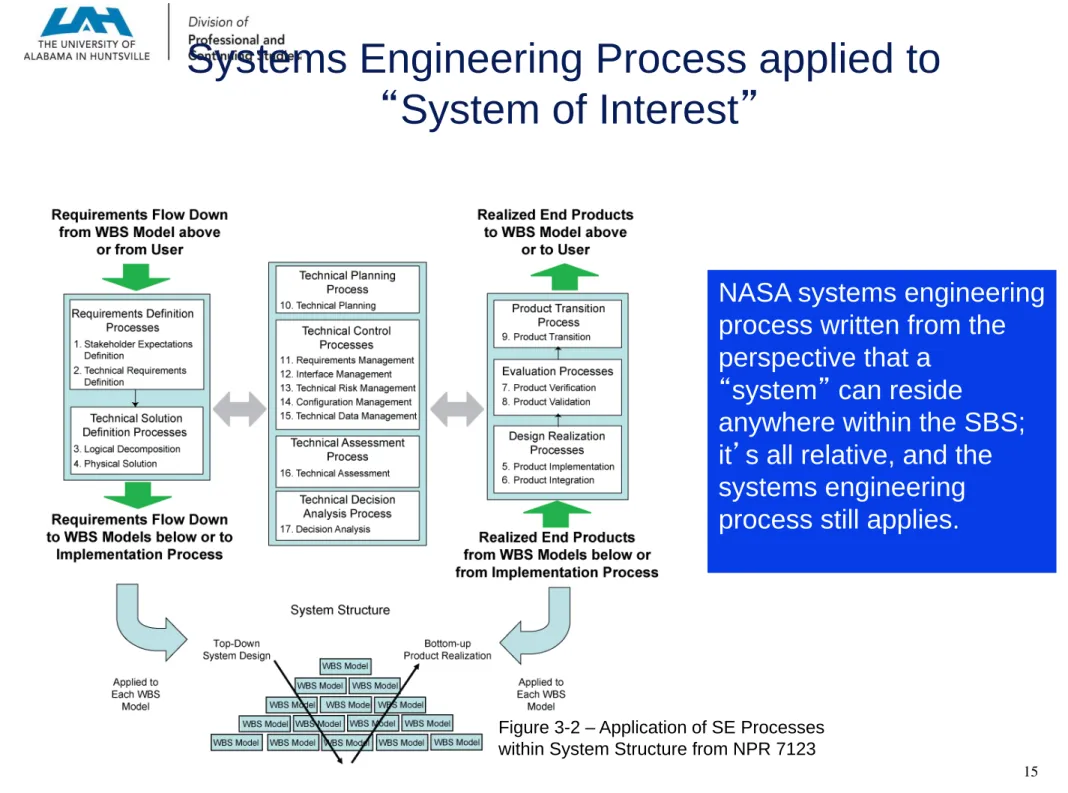
Systems Engineering Process applied to
“
System of Interest
”
Figure 3-2 – Application of SE Processes within System Structure from NPR 7123
NASA systems engineering process written from the perspective that a
“system” can reside
anywhere within the SBS; it’s all relative, and the systems engineering process still applies.
Key Points
• Systems analysis allows us to draw inferences concerning systems behavior on the basis of
inferences drawn concerning the behavior of the components of the system.
• A system is dependent on perspective; a component of a larger system can itself be considered a system that is, in turn, comprised of components.
• Systems analysis is not just product focused; it must also address the processes & operations of the
References
• IEEE Standard for Application and Management of
the Systems Engineering Process, IEEE Std
1220-2005, September 2005.
• NASA Systems Engineering Processes and
Requirements, NPR 7123, April 2013.
• Systems Engineering Fundamentals, Supplementary
Text Prepared by the Defense Acquisition University Press, Fort Belvoir, VA 22060-5565, January 2001.
• Systems engineering – System life cycle processes,
Lesson 2:
Introduction to
Objectives
• Provide an introduction to Modeling
• Provide an introduction to Simulation
What is Modeling?
• A model is an abstract, simplified representation of a part of reality and created for a particular purpose.
• The ultimate test of a model is how well it performs when it is applied to the problems it was designed to handle.
Building a Model – the 4 Step Process
1. Formulate the Problem. What is it that you wish
to know?
2. Outline the Model. Separate the various parts of
the system into unimportant, exogenous, and endogenous.
3. Is it Useful? If the model fits the situation, will we
be able to use it?
4. Develop and Test the Model. Use the model to
make predictions that can be checked against testing and/or experience.
Types of Models
• Deterministic
– mathematical models
• lift of an airplane wing • thrust of a rocket engine
• Stochastic
– random discrete event models
• wind velocities encountered by a flight vehicle during ascent • component failures during system operation
• Hybrid
– elements of mathematical & random discrete event models
The Black Box View of a Model
Transformation Inputs Outputs Controls Mechanisms Neglected Variables Exogenous Variables Endogenous VariablesA Deterministic System Model
--Lorenz Model of Atmospheric Dynamics
dx/dt = (y-x) dy/dt = x-xz-y dz/dt = xy-z x0 y0 z0 t0 x y z t dx/dt dy/dt dz/dt
x,y,z: cartesian coordinates for surface coordinates & altitude
t: time
: ratio of viscosity to thermal conductivity (10)
: nondimensional temperature gradient (28)
A Stochastic System Model
--The Random Walk
(Staggering Drunk)
x & y: cartesian coordinates of location
N: number of steps Decision Logic Random Number Stream x0 y0 N x y
Properties of Models
• Generality – the scope of the model
• Realism – the extent to which the model behaves
like the system being modeled
• Precision – the number of significant digits
accommodated & maintained by the model
Typically, generality is traded against precision for a given degree of realism in a model.
What is Simulation?
• Simulation is the process of
1. Developing a system model
2. Conducting experiments with this model for the purpose of understanding the behavior of the system or evaluating various strategies for the operation of the system
Simulation versus Models
• Model – defined earlier; an abstract representation of a system
• Simulation – an imitation of system performance over time to a predefined degree of fidelity
– design analyses (model the system & the environment) – breadboards (model the system)
– qualification testing (models the environment) – training (models the mission)
Conducting a Simulation – the 4 Step Process
1. Modeling. Refer to the 4 Step Model Process.
2. Strategic & Tactical Planning. What are the
experimental conditions (variable ranges & increments) for using the model?
3. Experimentation. Run the model on the specified
parameter sets.
4. Analysis of Results. What inferences may be
drawn from the data and what recommendations for problem resolution can be made?
Remarks
• The three main things to keep in mind when modeling
• Simplify
• Simplify
Key Points
• The four step process for model development
• The four step process for simulation development • Modeling vs. simulation
• Analysis vs. modeling & simulation
Everything we do for the remainder of this course builds on this foundation.
References
• Bender, Edward A., An Introduction to Mathematical
Modeling, Wiley, 1978.
• Blanchard, Benjamin S. & Wolter Fabrycky, Systems
Engineering and Analysis, 5th edition, Prentice-Hall,
2006.
• Buede, Dennis M., The Engineering Design of
Systems: Models and Methods, 2nd edition, Wiley,
2009
• Pritsker, A. Alan B., & C. Dennis Pegden,
Introduction to Simulation and SLAM, Wiley, 1979.
• Shannon, Robert E., Systems Simulation: the Art
Lesson 3:
Systems Analysis
and Life Cycles
Objectives
• Review the Systems Engineering Life Cycle
• Describe the Role of Systems Analysis within the context of the overall Systems Engineering Process
• Describe the Role of Systems Analysis over the Systems Engineering Life Cycle
The System Life Cycle per IEEE 1220
Ref: IEEE 1220, figure 7.
System Definition Subsystem Definition Preliminary Design Detailed Design Fabrication, Assembly, Integration, and Test (FAIT) Production Support Stages of Development a) System definition b) Subsystem definition
1) Preliminary design of subsystems
2) Detailed design of subsystem components 3) FAIT
Development Operations
Stages of Operations
a) Production b) Support
NASA Flight Project System Life Cycle
• Key Milestone Reviews
– Mission Concept Review
– Systems Requirements Review – Systems Design Review
– Preliminary Design Review – Critical Design Review
– Test Readiness Review
– Systems Acceptance Review – Flight Readiness Review
– Operational Readiness Review – Decommissioning Review Formulation Implementation Pre A Concept Studies A Concept Development B Preliminary Design C Detail Design D Fabrication, Assembly,
Integration, & Test
E
Operations & Sustainment
F
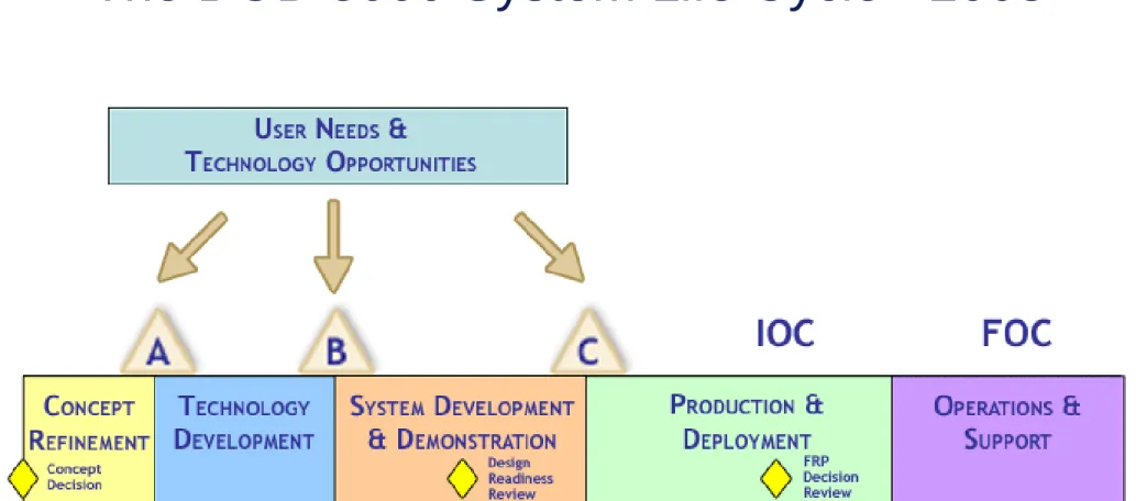
The DOD 5000 System Life Cycle - 2003
Figure 1 from DOD 5000.2
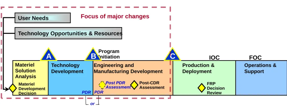
The DOD 5000 System Life Cycle - 2008
Figure 1 from DOD 5000.2
IOC Technology Development Production & Deployment Operations & Support FRP Decision Review FOC Materiel Solution Analysis Materiel Development Decision User Needs
Technology Opportunities & Resources
Program Initiation B
A C
Focus of major changes
Engineering and Manufacturing Development Post-CDR Assessment PDR PDR or Post PDR Assessment
Tailoring of DoD 5000.2 for National Security
Space Programs & Projects
NSS formally tailored DOD 5000.2 to suit small production lots (<50) in highly complex product developments.
Comparison of Life Cycle Models
System Definition Subsystem Definition Preliminary Design Detailed Design Fabrication, Assembly, Integration, and Test (FAIT) Production Support Development Operations Formulation Implementation Pre A Concept Studies A Concept Development B Preliminary Design C Detail Design D Fabrication, Assembly,Integration, & Test
E Operations & Sustainment F Disposal Concept Refinement Technology Development System Development & Demonstration Production & Deployment Operations & Support
Systems Analysis Supports Entire Development
Cycle
Ref: Buede Understand User
Requirements, Develop System Concept and
Acceptance Plan
Develop System Performance Specification And System Verification Plan
Expand Performance Specifications into CI “Design-to” Specifications and CI Verification
Plan
Evolve “Design-to” Specifications into “Build-to”
Documentation and Inspection Plan
Fab, Assemble, and Code to “Build-to”
Documentation
Inspect to “Build-to” Documentation
Assemble CIs and perform CI Verification
to CI “Design-to” Specifications
Integrate System and Perform System Verification to Performance Specifications
Demonstrate and Validate System to User Acceptance Plan S ys tem D es ign S ys tem D es ign Sys tem Va lid ati on Sys tem Va lid ati on & V eri fic ati on & V eri fic ati on System Development System Development … …
Success Criteria/Verification Requirements
Success Criteria/Verification Requirements
Requirements Validation Requirements Validation . . . . . .
Systems Development & Analysis
Systems Development & Analysis
Design Verification
Understand User Requirements, Develop
System Concept and Acceptance Plan
Develop System Performance Specification And System Verification Plan
Expand Performance Specifications into CI “Design-to” Specifications and CI Verification
Plan
Evolve “Design-to” Specifications into “Build-to”
Documentation and Inspection Plan
Fab, Assemble, and Code to “Build-to”
Documentation
Inspect to “Build-to” Documentation
Assemble CIs and perform CI Verification
to CI “Design-to” Specifications
Integrate System and Perform System Verification to Performance Specifications
Demonstrate and Validate System to User Acceptance Plan S ys tem D es ign S ys tem D es ign Sys tem Va lid ati on Sys tem Va lid ati on & V eri fic ati on & V eri fic ati on System Development System Development … …
Success Criteria/Verification Requirements
Success Criteria/Verification Requirements
Requirements Validation Requirements Validation . . . . . .
Systems Development & Analysis
Systems Development & Analysis
Design Verification
IEEE 1220 provides a process-centric view of the systems engineering
process, whereas
the “SE Vee”
provides a more temporal depiction.
Systems Analysis During Concept Development
Understand User Requirements, Develop
System Concept and Acceptance Plan
Develop System Performance Specification And System Verification Plan
Expand Performance Specifications into CI “Design-to” Specifications and CI Verification
Plan
Evolve “Design-to” Specifications into “Build-to”
Documentation and Inspection Plan
Fab, Assemble, and Code to “Build-to”
Documentation
Inspect to “Build-to” Documentation
Assemble CIs and perform CI Verification
to CI “Design-to” Specifications
Integrate System and Perform System Verification to Performance Specifications
Demonstrate and Validate System to User Acceptance Plan
S ys tem D e s ig n S ys tem D es ig n Sys tem Va lid atio n Sys tem Va lida tion & V eri fic atio n & V eri fica tio n System Development System Development … …
Success Criteria/Verification Requirements
Success Criteria/Verification Requirements
Requirements Validation Requirements Validation . . . . . .
Systems Development & Analysis
Systems Development & Analysis
Design Verification
Metrics
Metrics
SSTO Metric Example: Impact of Technologies - A
Baseline (AL Tankage) Aluminum/Lithium Composites Practical Limit of Vehicle Size ~ ~ 5 10 15 20 25 30 35 200 300 400 200 300 400 Vehi cl e D ry W e ig h , 10 00 # 25K to LEO
•Main Propulsion System •Propellant type •Storable vs cryo •Combo •Engine •Existing •New Development •Modified •Rover Deployment •Extendable ramp •Other
•Lander power supply
•Fuel cells •Batteries •Solar arrays •Nuclear •Combination •Primary Structure •Construction •Truss •Skin-stringer •Honeycomb •Isogrid •Materials •Composites •Metallic •RCS •Common prop. w/MPS •Storable •Cryo •Avionics •Degree of command and contol •IVHM
Concept Trades
•Lander configuration•Modular vs integrated design
•Horizontal vs vertical •Multiple ta
•Communication
•Direct to Earth vs relay sats
•High gain antennae vs omni
•High frequency band trades
Key Mission Events and Associated Trades
• Delta IV H Launch
– Extensive mass margin for baseline mission;
– Dual manifest opens cheapest path to full system (lander, rover, Nav/Comm)
• LOX / LH2 main engine
– Link to potential ISRU; look-ahead to manned systems
• Transfer and capture phases: Lander Main Engine vs. SEP
– Potential payload increase with SEP is minimal (at best); transfer and capture phases extend to years.
• Powered Descent and Landing: modified RL-10 (5klb thrust, throttle to 10%) alone
– Alternative (off-ramp) is combination of unmodified RL-10 with lower thrust auxiliary for final descent
– Development of modified RL-10 deemed less risky than mission and design complexity for alternative
Lander Capability-Current Mission
10.76 m
Common concept has excess capability for currently defined mission
Rover+Lander Payloads=1100kg
Current concept can land > 1100kg on lunar surface
LanderPayload
Element Mass(kg) Power(W) Volume Notes
Instrument1 M1 P1 V1 xyz1 Instrument2 M2 P2 V2 xyz2 Instrument3 M3 P3 V3 xyz3 Instrument4 M4 P4 V4 xyz4 Instrumentn Mn Pn Vn RoverPayload
Element Mass(kg) Power(W) Volume Notes
Instrument1 M1 P1 V1 xyz1 Instrument2 M2 P2 V2 xyz2 Instrument3 M3 P3 V3 xyz3 Instrument4 M4 P4 V4 xyz4 Instrumentn Mn Pn Vn
Systems Analysis During Detail Design
Understand User Requirements, Develop
System Concept and Acceptance Plan
Develop System Performance Specification And System Verification Plan
Expand Performance Specifications into CI “Design-to” Specifications and CI Verification
Plan
Evolve “Design-to” Specifications into “Build-to”
Documentation and Inspection Plan
Fab, Assemble, and Code to “Build-to”
Documentation
Inspect to “Build-to” Documentation
Assemble CIs and perform CI Verification
to CI “Design-to” Specifications
Integrate System and Perform System Verification to Performance Specifications
Demonstrate and Validate System to User Acceptance Plan
S ys tem D e s ig n S ys tem D es ig n Sys tem Va lid atio n Sys tem Va lida tion & V eri fic atio n & V eri fica tio n System Development System Development … …
Success Criteria/Verification Requirements
Success Criteria/Verification Requirements
Requirements Validation Requirements Validation . . . . . .
Systems Development & Analysis
Systems Development & Analysis
Design Verification
Understand User Requirements, Develop
System Concept and Acceptance Plan
Develop System Performance Specification And System Verification Plan
Expand Performance Specifications into CI “Design-to” Specifications and CI Verification
Plan
Evolve “Design-to” Specifications into “Build-to”
Documentation and Inspection Plan
Fab, Assemble, and Code to “Build-to”
Documentation
Inspect to “Build-to” Documentation
Assemble CIs and perform CI Verification
to CI “Design-to” Specifications
Integrate System and Perform System Verification to Performance Specifications
Demonstrate and Validate System to User Acceptance Plan
S ys tem D e s ig n S ys tem D es ig n Sys tem Va lid atio n Sys tem Va lida tion & V eri fic atio n & V eri fica tio n System Development System Development … …
Success Criteria/Verification Requirements
Success Criteria/Verification Requirements
Requirements Validation Requirements Validation . . . . . .
Systems Development & Analysis
Systems Development & Analysis
Design Verification TPM Application -- Example Bels 4.0 4.1 4.2 4.3 4.5 4.4 Actual Measure Design Profile Design Requirements (or Product Spec) Acoustics
Idle
Baseline
Measurement Events
Define (for each deviation from plan) • What Changed vs Expectations • How recovered
• Sensitivity to parameter variations/changes • Configuration H/W SCSI code Servo code Electronics Other •Test equipment Test Phase Entry Define at Entry Calendar Dates
Systems Analysis During Integration
Understand User Requirements, Develop
System Concept and Acceptance Plan
Develop System Performance Specification And System Verification Plan
Expand Performance Specifications into CI “Design-to” Specifications and CI Verification
Plan
Evolve “Design-to” Specifications into “Build-to”
Documentation and Inspection Plan
Fab, Assemble, and Code to “Build-to”
Documentation
Inspect to “Build-to” Documentation
Assemble CIs and perform CI Verification
to CI “Design-to” Specifications
Integrate System and Perform System Verification to Performance Specifications
Demonstrate and Validate System to User Acceptance Plan
S ys tem D es ig n S ys tem D e s ig n Sys tem Va lida tio n Sys tem Va lid atio n & V eri fica tio n & V eri fic atio n System Development System Development … …
Success Criteria/Verification Requirements
Success Criteria/Verification Requirements
Requirements Validation Requirements Validation . . . . . .
Systems Development & Analysis
Systems Development & Analysis
Design Verification
Understand User Requirements, Develop
System Concept and Acceptance Plan
Develop System Performance Specification And System Verification Plan
Expand Performance Specifications into CI “Design-to” Specifications and CI Verification
Plan
Evolve “Design-to” Specifications into “Build-to”
Documentation and Inspection Plan
Fab, Assemble, and Code to “Build-to”
Documentation
Inspect to “Build-to” Documentation
Assemble CIs and perform CI Verification
to CI “Design-to” Specifications
Integrate System and Perform System Verification to Performance Specifications
Demonstrate and Validate System to User Acceptance Plan
S ys tem D es ig n S ys tem D e s ig n Sys tem Va lida tio n Sys tem Va lid atio n & V eri fica tio n & V eri fic atio n System Development System Development … …
Success Criteria/Verification Requirements
Success Criteria/Verification Requirements
Requirements Validation Requirements Validation . . . . . .
Systems Development & Analysis
Systems Development & Analysis
Design Verification EQ.PROP REM Demonstrated during thruster qualification testing. Analysis Predicted Throughput: 92.6 lbm Expected Margin: 107 lbm DERVD 3.6 Spacecraft IPS Derived
Requirement IOC AXAF.95.350.121 AXSC 3.2.9.2.1 Heaters 376245 Propellant Throughput 200 lbm EQ.PROP REM Demonstrated during thruster qualification testing. Analysis DERVD 3.6 Spacecraft IPS Derived
Requirement IOC AXAF.95.350.121 AXSC 3.2.9.2.1 Heaters 376244 Total Pulses (each
thruster) 50,000 EQ.PROP REM Demonstrated during thruster qualification testing. Analysis DERVD 3.6 Spacecraft IPS Derived
Requirement IOC AXAF.95.350.121 AXSC 3.2.9.2.1 Heaters 376243 RCS Minimum Specific
Impulse (inlet press. = 250 psia) 225 sec (BOL steady state)
EQ.PROP REM Demonstrated during
thruster qualification testing. Analysis DERVD 3.6 Spacecraft IPS Derived
Requirement to be resolved AXSC 3.2.9.2.1 Heaters
376242 RCS Thrust 21 lbf + 5% (at 250 psia inlet pressure)
EQ.PROP REM Demonstrated during
thruster qualification testing. Analysis DERVD 3.6 Spacecraft IPS Derived
Requirement IOC AXAF.95.350.121 AXSC 3.2.9.2 Thermal Control Subsystem (TCS) 376241 RCS Minimum Impulse Bit TBD SE30.TRW Verified by analysis. Analysis DERVD 3.6 Spacecraft IPS Derived
Requirement IOC AXAF.95.350.121 AXSC 3.2.9.1 Structures & Mechanical Subsystem 376240 LAE Location + 3 inches EQ.LAE Verified by measurement at the engine level. Analysis
DERVD 3.6 Spacecraft IPS Derived Requirement IOC AXAF.95.350.121 AXSC 3.2.9.1 Structures & Mechanical Subsystem
376239 LAE Thrust Vector Alignment Component + 0.25 degrees Verification Event Verification Requirements Planned Method Capability/Margins (Physical, Functional, Performance) Requirement Source (Parent Requirement) Performance Requirement (Spacecraft Specification Paragraph) EQ.PROP REM Demonstrated during thruster qualification testing. Analysis Predicted Throughput: 92.6 lbm Expected Margin: 107 lbm DERVD 3.6 Spacecraft IPS Derived
Requirement IOC AXAF.95.350.121 AXSC 3.2.9.2.1 Heaters 376245 Propellant Throughput 200 lbm EQ.PROP REM Demonstrated during thruster qualification testing. Analysis DERVD 3.6 Spacecraft IPS Derived
Requirement IOC AXAF.95.350.121 AXSC 3.2.9.2.1 Heaters 376244 Total Pulses (each
thruster) 50,000 EQ.PROP REM Demonstrated during thruster qualification testing. Analysis DERVD 3.6 Spacecraft IPS Derived
Requirement IOC AXAF.95.350.121 AXSC 3.2.9.2.1 Heaters 376243 RCS Minimum Specific
Impulse (inlet press. = 250 psia) 225 sec (BOL steady state)
EQ.PROP REM Demonstrated during
thruster qualification testing. Analysis DERVD 3.6 Spacecraft IPS Derived
Requirement to be resolved AXSC 3.2.9.2.1 Heaters
376242 RCS Thrust 21 lbf + 5% (at 250 psia inlet pressure)
EQ.PROP REM Demonstrated during
thruster qualification testing. Analysis DERVD 3.6 Spacecraft IPS Derived
Requirement IOC AXAF.95.350.121 AXSC 3.2.9.2 Thermal Control Subsystem (TCS) 376241 RCS Minimum Impulse Bit TBD SE30.TRW Verified by analysis. Analysis DERVD 3.6 Spacecraft IPS Derived
Requirement IOC AXAF.95.350.121 AXSC 3.2.9.1 Structures & Mechanical Subsystem 376240 LAE Location + 3 inches EQ.LAE Verified by measurement at the engine level. Analysis
DERVD 3.6 Spacecraft IPS Derived Requirement IOC AXAF.95.350.121 AXSC 3.2.9.1 Structures & Mechanical Subsystem
376239 LAE Thrust Vector Alignment Component + 0.25 degrees Verification Event Verification Requirements Planned Method Capability/Margins (Physical, Functional, Performance) Requirement Source (Parent Requirement) Performance Requirement (Spacecraft Specification Paragraph)
MANDATORY PROCEDURES FOR MAJOR DEFENSE ACQUISITION PROGRAMS (MDAPS)
AND MAJOR AUTOMATED INFORMATION SYSTEM (MAIS)
ACQUISITION PROGRAMS June 2001 Office of Under Secretary of Defense (Acquisition, Technology, and Logistics) Office of Assistant Secretary of Defense (Command, Control, Communications, and Intelligence) Office of Director, Operational Test and
Evaluation
NASA Procedures and Guidelines
NPG: 7120.5A Effective Date: April 3, 1998 Expiration Date: April 3, 2003 Responsible Office: Code AE/Office of Chief Engineer
NASA Program and Project Management Processes and Requirements
Process Relations for Engineering a System
We will examine the role of Systems Analysis in the Systems Engineering Process as defined in IEEE-1220 in the next lesson.IEEE 1220 SEP Map to
“
SE VEE
”
Understand User Requirements, Develop
System Concept and Acceptance Plan
Develop System Performance Specification And System Verification Plan
Expand Performance Specifications into CI “Design-to” Specifications and CI Verification
Plan
Evolve “Design-to” Specifications into “Build-to”
Documentation and Inspection Plan
Fab, Assemble, and Code to “Build-to”
Documentation
Inspect to “Build-to” Documentation
Assemble CIs and perform CI Verification
to CI “Design-to” Specifications
Integrate System and Perform System Verification to Performance Specifications
Demonstrate and Validate System to User Acceptance Plan
S ys tem D es ign S ys te m D e s ig n Sys tem Va lid ati on Sys tem Va lid ati on & V eri fic ati on & V eri fic ati on System Development System Development … …
Success Criteria/Verification Requirements
Success Criteria/Verification Requirements
Requirements Validation Requirements Validation . . . . . .
Systems Development & Analysis
Systems Development & Analysis
Design Verification
Understand User Requirements, Develop
System Concept and Acceptance Plan
Develop System Performance Specification And System Verification Plan
Expand Performance Specifications into CI “Design-to” Specifications and CI Verification
Plan
Evolve “Design-to” Specifications into “Build-to”
Documentation and Inspection Plan
Fab, Assemble, and Code to “Build-to”
Documentation
Inspect to “Build-to” Documentation
Assemble CIs and perform CI Verification
to CI “Design-to” Specifications
Integrate System and Perform System Verification to Performance Specifications
Demonstrate and Validate System to User Acceptance Plan
S ys tem D es ign S ys te m D e s ig n Sys tem Va lid ati on Sys tem Va lid ati on & V eri fic ati on & V eri fic ati on System Development System Development … …
Success Criteria/Verification Requirements
Success Criteria/Verification Requirements
Requirements Validation Requirements Validation . . . . . .
Systems Development & Analysis
Systems Development & Analysis
Design Verification
In IEEE 1220, Design Verification interacts with Systems Analysis via Requirements Analysis, Functional Analysis, Or Synthesis.
Key Points
• Systems analysis supports the systems engineering process from the very early phases through system operation.
• Early in the development cycle, systems analyses
tend to be more broad in scope with less fidelity; over time, the systems analyses tend to more narrow
References
• Buede, Dennis M. The Engineering Design of Systems, 2nd
edition, Wiley, 2009.
• IEEE Standard for Application and Management of the Systems Engineering Process, IEEE Std 1220-2005, September 2005.
• NASA Systems Engineering Processes and Requirements, NPR 7123, April 2013.
• National Security Space Acquisition Policy, NSS 03-01, December 2004
• Systems Engineering Fundamentals, Supplementary Text Prepared by the Defense Acquisition University Press, Fort Belvoir, VA 22060-5565, January 2001.
• Operation of the Defense Acquisition System, DoD Instruction 5000.2, December 2008 (Note: superceded by DoD 5000.02 with a current date of November 2013, but 5000.2 is the correct reference for the information used).
Lesson 4:
Systems Engineering Role of
Systems Analysis
Objectives
• Review the formal roles of systems analysis in the execution of the systems engineering process as described in IEEE-1220.
– Key functions – Key interactions
The project shall perform the tasks of systems analysis for the purpose of resolving conflicts
identified during requirements analysis,
decomposing functional requirements and allocating
performance requirements during functional
analysis, evaluating the effectiveness of alternative design solutions and selecting the best design
solution during synthesis, assessing system
effectiveness, and managing risk factors throughout
the systems engineering effort. Systems analysis
provides a rigorous quantitative basis for
establishing a balanced set of requirements and for ending up with a balanced design. The tasks associated with systems analysis are identified in Figure 16. Even if a trade-off analysis is not done, an overall assessment of the system effectiveness
should be completed.
Ref: IEEE-1220, Figure 16
6.7.1 Assess Requirement Conflicts
The project assesses conflicts among
requirements and constraints identified during requirements analysis to identify alternative functional and performance requirements, where necessary.
Requirements trade-off analyses and
assessments are performed to identify the
recommended set of requirements and constraints in terms of risk, cost, schedule, and performance impacts.
6.7.2 Assess Functional Alternatives
The project assesses possible
alternative subfunction arrangements for the decomposition of a function and
for the allocation of allocable
performance requirements to the
subfunctions during functional analysis. Functional trade-off analyses and
assessments are performed to identify
the recommended set of
subfunctions for each function and performance requirement allocations
in terms of risk, cost, schedule, and performance impacts.
6.7.3 Assess Design Alternatives
The project assesses potential
groupings and allocations of functions
from the verified functional architecture and identified design alternatives during synthesis. Design trade-off analyses and assessments are performed to identify the recommended design trade-offs in terms of risk, cost, schedule, and performance impacts.
6.7.4 Identify Risk Factors
The project assesses requirements and constraints from
requirements analysis, subfunction arrangements resulting from functional decomposition, allocation of subfunctions to functional elements, design decisions made during synthesis, and design elements of the design architecture, to identify the risk factors
to successful completion of the project. These evaluations
should be made from an entire life cycle perspective.
Identification of risk should be in a form to understand the following:
a) The circumstances that might lead to risk factor occurrence and the probability of occurrence
b) How the risk factor can be recognized if it does occur c) How the risk factor affects cost, schedule, and
performance.
Identified risks are prioritized based upon criticality to the
successful development of the system. Acceptable levels of risk should be identified, depending on the stage of development, to provide a basis for establishing and monitoring risk reduction activities and mitigating unacceptable risks.
6.7.5 Define Trade-off Analysis Scope
The project should define the scope of the trade-off analysis to be conducted. A trade-off analysis can be
a) Judgmental—a selection made based on the judgment of the analyst or designer, which does not require the rigor of a more formal study and for which the consequences are not too important; one alternative that is clearly
superior to others; and/or time that may not be available for a more formal approach (most trade-off analyses done in accomplishing the tasks of the SEP are of the judgmental type);
b) Informal—follows the same methodology of a formal trade-off analysis but is not documented as formally and is of less importance to the acquirer;
c) Formal—formally conducted with results reviewed at technical reviews.
Informal and formal trade-off analysis objectives, execution, data collection requirements, schedule of activities, analysis of results, and expected outcomes need to be fully defined. Each trade-off analysis is conducted for the purpose of selecting among competing alternatives to support stakeholder needs, system effectiveness, design to cost, or life cycle cost
6.7.5.1 Select Methodology and Success Criteria
The project selects the general approach, resources, and procedures for performing trade studies based upon the trade-study definition, its level of importance, and
availability of tools, facilities, special
equipment, and related resources. The project
also lists the set of selection criteria, which includes factors that characterize what makes a specific alternative desirable, such as cost, schedule, performance and risk; life cycle quality factors; reuse; and size, weight, and
power consumption. Adverse qualities as well
as favorable qualities should be included as criteria.
6.7.5.2 Identify Alternatives
The project identifies and lists the viable alternative solutions to be evaluated. Each alternative should be compared with respect
to completeness, and sensitivity analysis
should be conducted to understand how each alternative withstands changes in the environment, technology base, or within the
bounds of the evolutionary strategy.
6.7.5.3 Establish Trade-Study Environment
The project establishes metrics for each criterion that characterizes how well various alternatives satisfy the criterion. In addition, the project
establishes weighting factors for each criterion, which distinguish the degree of importance to the
trade-off analysis definition. Models
(representative or simulations) are established, when needed, to support conduct of a formal or
informal trade study. The selection of models
depends on the nature of the trade-off analysis, the development stage, the type of information needed, and the characteristics of interest for an alternative. Models should be validated prior to application in a trade-off analysis.
6.7.6 Conduct Trade-off Analysis
The project completes tasks 6.7.6.1 through 6.7.6.4, to the degree appropriate, to complete trade-off analyses for the following:
a) Requirements analysis to both resolve conflicts with and satisfy stakeholder/market needs, requirements, and constraints
b) Functional analysis to support decomposition of
functions into subfunctions and to allocate
performance requirements
c) Synthesis to support design decisions
Formal and informal trade-off analyses are conducted
under controlled conditions to generate data pertaining
to each alternative. The results of the trade-off
analyses are recorded and analyzed to quantify the impact each alternative has on the system or technical effort. These results are compared against the success criteria to determine which alternative is
recommended.
6.7.6.1 Analyze Life Cycle Costs
The project analyzes the costs to the project and to
the acquirer for alternative system approaches considered in a trade-off analysis or system
effectiveness assessment. Life cycle cost analyses
a) Provide requisite cost information to support trade-off analysis decisions.
b) Provide requisite cost information for system effectiveness assessments.
c) Include the cost of development, manufacturing, test, distribution, operations, support, training, and disposal.
d) Include established design-to-cost goals, a current estimate of these costs, and known uncertainties in these costs.
e) Identify the impacts on life cycle cost of proposed changes.
6.7.6.2 Analyze System and Cost-Effectiveness
The project analyzes the relationships between
system effectiveness and life cycle costs to
a) Determine performance impacts on costs. b) Understand value added as a function of cost. c) Support identification of performance objectives
and requirements.
d) Support allocation of performance to functions. System and cost-effectiveness analyses are
conducted on life cycle processes of manufacturing, test, distribution, operations, support, training, and disposal to support inclusion of life cycle quality factors into system product designs, and to support the definition of functional and performance
requirements for life cycle processes. The results of these analyses are used in evaluating trade-off
analysis alternatives and for effectiveness assessments of the system.
6.7.6.3 Analyze Safety and Environmental Impacts
The project identifies safety and environmental impacts associated with system implementation.
Applicable environmental laws and regulations should be identified, and the project should ensure that these
are complied with by any alternative solution. The
project completes an environmental impact and safety analysis to determine the impact on and by system products and the impact of their life cycle
processes on the environment or to personnel. Use of
materials or generating by-products that present a known hazard to the environment are to be avoided to the extent feasible. Where not feasible, provisions may be provided for proper handling, storage, and disposal of hazardous materials or by-products.
Results of these analyses influence trade-off analysis recommendations and assessments of system
effectiveness.
6.7.6.4 Quantify Risk Factors
The project quantifies the impact of identified risk factors on the system or alternative being considered based on
exposure to the probability of an undesirable
consequence. For system effectiveness
assessments, each element of the system architecture developed to date is assessed to determine what can go wrong, and if it goes wrong, what impact it may have on the
system. For trade-off analyses, risk levels
assessed during life cycle cost, system and cost-effectiveness, and environmental
impact analyses are prioritized and reported as part of trade-off analysis
recommendations.
6.7.7 Select Risk-Handling Options
The project assesses various risk-handling options to select those that may mitigate risks consistent with the current stage of development and risk-management policies set by the project. Risk, which may be reduced by lessening either the likelihood or the impact, or both, may be accepted given the cost, schedule, and performance impacts and planned mitigation approaches. An analysis of the risk-handling options should be accomplished to quantify costs and effects on the probability and impact of risk. The project should select those risk-handling options that are feasible and that reduce risks to acceptable levels with the best cost/benefit ratio. The expected remaining risks after risk-handling mitigation efforts are implemented should be identified and quantified. Throughout risk identification, quantification, and handling, integration is needed from lower levels of the system architecture up through the system level to understand cause-and-effect interactions. Risk reduction approaches and expected remaining risks are included in a risk reduction plan, which is included in trade-off analysis recommendations and effectiveness
assessment reports. The complete risk reduction effort is documented in the engineering plan and integrated into the master schedule for the next stage of development, and briefed at appropriate technical reviews.
6.7.8 Select Alternative Recommendation
The project utilizes the results of trade-off analyses and risk-reduction planning information to recommend a preferred alternative to the decision maker. The project should assess the trade-off analysis to assure that the
methodologies and data collection instrumentation were sufficient to
support a fair and complete evaluation.
Each recommendation should be
presented in terms of configuration and cost, schedule, performance, and risk impact.
74
6.7.9 Trade-offs and Impacts
The project documents the
recommended trade-off alternative(s) with corresponding impacts and
presents the results to the appropriate decision makers within the SEP activity who are making or requesting the
trade-off analysis. The final alternative
selection is made based on the criteria established to judge a desirable
solution. Key trade-off analysis activities, decisions, rationale, and recommendations are documented in the integrated repository.
Ref: IEEE-1220, Figure 16
Note: key interfaces to the Requirements Analysis, Functional Analysis, Synthesis, & Control processes.
6.7.10 Design Effectiveness Assessment
The project determines the
effectiveness of the current system design based on the results of the
assessments and analyses. The
results of these assessments and analyses are documented in the integrated repository and briefed at appropriate technical and project reviews.
Ref: IEEE-1220, Figure 16
Note: key interface to the Control process.
Process Dependencies
• Requirements Conflicts & Issues
– Consistency of the system technical requirements with the system being engineered
• Product Characteristics
– System configuration verified includes manufacturing tolerances & deviations
• Verification Results
– Requirements, reference standards & calibration data, discrepancies between expected & actual results
• Validation Results
– Procedures & compliance data
Key Points
• Systems analysis is a key component of the systems engineering process.
• Per IEEE-1220, systems analysis exists to enable
other processes -- Requirements Analysis, Functional Analysis, Synthesis, & Control processes.
• Subsequent modules will address various modeling & simulation methods & techniques employed
throughout the system life cycle.
Question: Why do we do systems analysis?
Answer: To provide a basis for execution of the systems
References
• IEEE Standard for Application and Management of
the Systems Engineering Process, IEEE Std
Lesson 5:
Objectives
• Describe the system engineering process in the context of different types & applications of models.
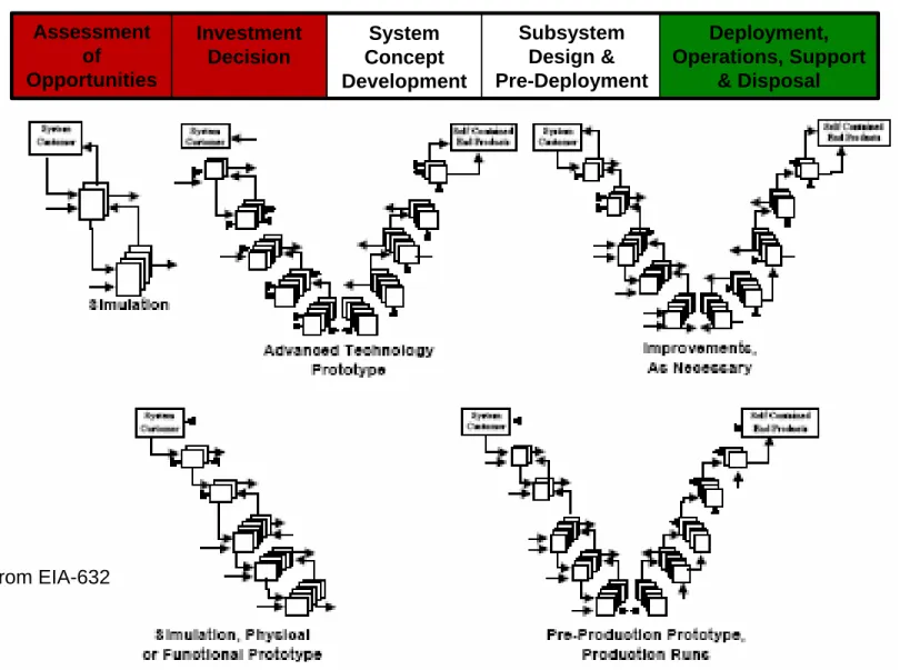
Figure B-1 from EIA-632
Modeling & Simulation over the Life Cycle per
EIA 632
Assessment of Opportunities Investment Decision System Concept Development Subsystem Design & Pre-Deployment Deployment, Operations, Support & DisposalAdvantages of Modeling and Simulation
Systems Engineering uses of Models
• Creation of a shared vision.
• Communication of the shared vision. • Testing the shared vision.
• Estimation or prediction of some quantitative measure associated with the system.
• Selection of one design option of other design options.
Models and Modeling
• A model is an incomplete representation of reality. It may be a physical, quantitative, qualitative or mental representation.
• The purpose of a model is to answer questions about a system before it is fully developed. These
questions can be:
– definitive, meaning how do we define the system
– descriptive, meaning how will a system perform give a set of inputs
– normative, meaning how an individual or organization ought to think about a product or process
Taxonomy of Models
(ref. Table 3.1, Buede)
Model
Categories Model Subcategories
Typical Systems Engineering Questions
Physical Full-scale mock-up Subscale mock-up Breadboard How much? How often? How good? Do they match? Quantitative Analytic Simulation Judgmental How much? How often? How good? Qualitative Symbolic Textual Graphic
What needs to be done? How well?
By what? Mental Explanation
Prediction Estimation
Quantitative Models
Launch Systems Analysis
Technical Models Cost & Operations Models Economic Model
System Weights & Sizing INTROS Development & Unit Costs NAFCOM/PRICE/SEER Facilities & Operations Costs NROC/AATE $ / lb to Orbit
Business Case Closure Business Model
Trajectory POST
Flight Rate Facilities & Ops Cost Vehicle Acquisition Costs Weights
& Vehicle Description
Vehicle Performance
Reliability / Safety
Risk Model Vehicle Losses System Weights & Sizing CONSIZ Trajectory OPGUID System Weights, Sizing & Trajectory
Qualitative Model -- Schematic Block Diagram
Notes on Modeling
• Begin modeling by defining what question(s) you need to answer.
• Modeling is iterative; this includes development, testing and refinement.
– Verification checks to see if the model is built
correctly—i.e. represents the system as intended . – Validation checks to see if the representation
matches the real world system.
– Input pedigree, results uncertainties, results robustness, and model conservatism are all
important additional parameters which should be iteratively refined.
Model-Based Systems Engineering Process
Requirements Gathering & Operational Analysis
•Identify Source Material, •Operational Context, Use Cases,
Scenarios, Information Exchange •Establish Initial Requirements Set •Establish Design Constraints •Capture Issues / Risks / Decisions
Logical Architecture Analysis
•System Behavior Threads •Integrated Behavior Models •Derive Functional / Performance
Requirements •Define I/O
•Define Effectiveness Measures
Physical Architecture Analysis
•System Structure (i.e., Hierarchy of System Equipment)
•Interfaces between Equipment •Allocate Logical Behavior and
Non-Functional Requirements
•Risk Assessment
•Compliance & Cost Assessment •Design Verification & Validation
Product Evaluation & Document Generation
Analysis Results Specifications
•Test Planning
•Select Design Solution •Document Generation
Requirements Model Logical Architectures Physical Architectures
Equipment List
Technical Rules, Standards, and
R1-1 R1 R2 R Issue Risk F1 F5 F2 F3 F4
These Primary Concurrent / Iterative Activities Are Performed For Each Product/System Architecture Design Layer
These Primary Concurrent / Iterative Activities Are Performed For Each Product/System Architecture Design Layer
System of Systems Requirements Gathering
& Operational Analysis
•Identify Source Material, •Operational Context, Use Cases,
Scenarios, Information Exchange •Establish Initial Requirements Set •Establish Design Constraints •Capture Issues / Risks / Decisions
Logical Architecture Analysis
•System Behavior Threads •Integrated Behavior Models •Derive Functional / Performance
Requirements •Define I/O
•Define Effectiveness Measures
Physical Architecture Analysis
•System Structure (i.e., Hierarchy of System Equipment)
•
Interfaces between Equipment •
Allocate Logical Behavior and Non-Functional Requirements
-•Risk Assessment
•Compliance & Cost Assessment •Design Verification & Validation
Product Evaluation & Document Generation
Analysis Results Specifications
•Test Planning
•Select Design Solution •Document Generation
Requirements Model Logical Architectures Physical Architectures
Equipment List
Technical Rules, Standards, and Conventions
R1-1 R1 R2 R Issue Risk R1-1 R1 R2 R Issue Risk F1 F5 F2 F3 F4 F1 F5 F2 F3 F4
These Primary Concurrent / Iterative Activities Are Performed For Each Product/System Architecture Design Layer
These Primary Concurrent / Iterative Activities Are Performed For Each Product/System Architecture Design Layer
Cross-reference of IEEE 1220 SE Process to a
Model-based SE Process
System Definition Develop Allocated Architecture Develop Physical Architecture Develop Functional Architecture Manage Process Develop Specification& & & &
Originating Requirements Specifications System Definition Develop Allocated Architecture Develop Physical Architecture Develop Functional Architecture Manage Process Develop Specification
& & & &
Originating
Requirements Specifications
Hierarchical refinement of functional & physical
SE Models Are the Infrastructure
of the SE Process
• Missions are really top level functions from an operational point
of view.
• We acquire assets because we need them to accomplish a
mission.
– Not just hardware, but plans, procedures, etc.
• We specify requirements in order to acquire the assets we need.
• The functional architecture serves as the tie between the
operational missions and the design requirements.
• At any given level in the system engineering hierarchy:
– Start with the Functions allocated to your Component in the allocated architecture.
– Refine the functional architecture model until each leaf-level function can be allocated to a single child Component.
– Populate the physical architecture with your new child Components. – Specify Requirements for each sub-Component. Link constraints
directly to the child Components they affect, and functional requirements to Functions.
Top Level Systems Engineering Process
System Definition Develop Allocated Architecture Develop Physical Architecture Develop Functional Architecture Manage Process Develop Specification& & & &
Originating
Requirements Specifications
Define the System Requirements,
including background information to fill in all of the project requirements and the
operational concept
Define the design solutionone
hierarchal level below the System level that satisfies the system requirements and all of the stakeholder objectives. This
includes allocated and derived requirements, trade studies,