THE PUSH-FIT SOLUTION FOR UNDERFLOOR HEATING
Installation and
Technical Guide
The John Guest Group has a long established reputation as a world leading manufacturer of push-fit fittings, tube and other fluid control products. A reputation built on producing consistently high quality products with an ongoing commitment to value engineering and product development.
Worldwide Connections
The strictest control is maintained by virtue of the fact that design and manufacture is carried out in modern purpose built manufacturing centres in west London and at Maidenhead in Berkshire. Maintaining control over the whole process from initial tool design and tool making through to final assembly and testing ensuring that only products of the highest quality are produced.
The company believe it is this commitment to quality that has led to it receiving prestigious awards from many of the world’s leading testing and approvals organisations.
John Guest is a preferred supplier to many international companies.
A commitment to quality is at the heart of the John Guest Philosophy
Quality Manufacture
Speedfit PEX Fittings and Barrier Pipe. K24076, K24077 and K24078
British Gas Service
BS7291 No. KM39767
e
Members of the Technical Support Team are available to help you get the best from your Speedfit Underfloor Heating System. To obtain an estimate send us a plan of the area where underfloor heating is required, indicating the preferred location of the manifold and intended floor construction.
An estimate will be prepared and when approved and an order placed, the Speedfit CAD
Design Service will provide a detailed drawing showing pipe layout, flow rates, suggested zone temperatures and advice on commissioning. A member of our national team of Technical Support Engineers will be available to offer on-site support during the installation process.
Technical Help Desk:
01895 425333 | [email protected]
The JG Speedfit Technical Advisory Service is available to assist and advise on all aspects of using the Speedfit System. The service is available between 8.00am and 5.00pm Monday to Friday.
Design Service and Technical Support
CAD Design Service
The Speedfit System for Underfloor Heating has been designed to be as quick and easy as possible to install with component parts manufactured under an ISO9001 Quality Management System. The System has water pumped from a boiler or other heat source to a pump pack where it is mixed to approximately
50ºC then distributed via a manifold to heating circuits made using Speedfit Barrier Pipe. The temperature and volume of water is altered to maintain the requirements of the system. The pipe is laid in concrete or suspended just below the surface of timber flooring.
A wide range of electrical components means the system can have as much control as required.
CONTENTS
CONTENTS:
UNDERFLOOR HEATING
PREPARATION CONSIDERATIONS
PIPE INSTALLATION
JG UFH MANIFOLD & PUMP PACK INSTALLATION
p6-9 p10-19 p20-33 p34 HEATING CONTROLS p36-41
COMMISSIONING CHECKLIST
FREQUENTLY ASKED QUESTIONS & TROUBLESHOOTING
FILLING & TESTING
p42-43
p46-47
p48-49
START-UP & COMMISSIONING
p44-45
3
3
Underfloor heating provides the most comfortable, even warmth of any heating system. It is economical to run and virtually maintenance free. Warm water from a heat source such as a boiler or heat pump is distributed via a manifold to heating circuits made using Speedfit Barrier Pipe. The pipe can be installed in a screed, floating or suspended timber floor.
In screeded floors, the pipe is laid on insulation and then covered with a screed which can be laid almost any type of floor covering.
For timber floors, spreader plates are laid between the joists and the floor decking or on the underside of the floor. Speedfit Pipe is pushed into the grooves on the plates.
The Floor area is typically warmed to between 25ºC and 28ºC, providing an even distribution of heat at only slightly higher than room temperature. The system is controlled by one or more thermostats which control the manifold and boiler as required.
The heat is concentrated where it is most needed for comfort and efficiency.
By contrast, radiators transfer heat from a relatively small area at a much higher temperature than the space being heated.
The radiator system heats mainly by convection. This results in the floor being the coolest place in the room, with the mass of warm air at ceiling level.
Ceiling 18oC Ceiling24oC Floor 24oC 18FlooroC
Underfloor Heating
UNDERFLOOR HEA
TING
The Speedfit Underfloor Heating System offers many benefits to the consumer. These include:
Efficiency Savings
Underfloor Heating Systems are designed to operate at lower temperatures than radiator systems, making them especially suitable for condensing boilers and heat pumps. This results in reduced energy consumption and lower heating costs for the building.
Installation
It is simple to install, requiring the minimum of installation effort and little maintenance.
Comfort
The system uses mainly radiant heat, the most comfortable form of heating, giving an even distribution of warmth over the whole room.
Space
The system is unobtrusive and space saving which means every square metre of floor and wall space can be utilised giving freedom of interior design.
Noise
Compared to radiator systems the system is virtually silent running.
Health
Dust is minimised reducing the problem of house dust mites. Reduced numbers of hot surfaces and sharp edges minimise risk of burns or injury.
Control
Underfloor heating is easy to control and unlike conventional radiator systems, makes use of multi-zoning so each room benefits from individual time and temperature control resulting in a more flexible heating system with lower running costs.
Environment
Underfloor heating is suitable for use with the most energy efficient and environmentally friendly heating systems including condensing boilers, solar power and heat pumps.
The Speedfit Underfloor Heating System is suitable for most floor finishes, including ceramic tiles, carpets, vinyl and laminate.
However, the thermal resistance of the floor covering will have a marked effect on the performance of the heating system.
Advice on the use of floor coverings and their effect on the performance of a system is available from our Technical Help Desk.
For information on the effect of different floor finishes please refer the table on page 11.
FEATURES & BENEFITS
FLOOR FINISHES
AND COVERING
SET BACK - EXPLAINED
Compared to other forms of heating, underfloor heating can have a relatively slow response time, taking longer to heat up and cool down than radiator systems.In order to reduce running costs and to have realistic heat up and cool down response times, rather than the system being switched off, the temperature setting is reduced by about 4ºC. This is called set back because the system is turned down not off.
With the Speedfit System, set back can be achieved in two ways:
Individual Programming
Programmable Room Thermostats can be installed in each zone. They give individual time and temperature control, alternating between daytime and set back temperatures.
Centralised Programming
The Dial Set Back Room Thermostat has its own ‘Daytime’ and ‘Set Back’ time controlled centrally using a Touch Screen Time Clock.
The Whole Floor Acts as a Heat Source
As the chart above shows, people are more comfortable when their feet are in a warm area and their head is slightly cooler.
A system using radiators will have colder air at the bottom of a room which places your feet in the wrong place for comfortable living. This is because cold air is more dense (heavy) and it is pulled downwards by gravity.
In contrast, Underfloor Heating heats the whole floor. This means that the warmest space is the area nearest the floor, which matches the preferred heat profile. In practice, normal comfort can be achieved at a lower air temperature than with conventional radiators because underfloor heating systems heat mainly by radiated energy, just like the energy from the sun.
Radiant energy is emitted by the floor giving an even distribution of heat. This means no cold spots, hot ceilings or cold feet.
In its simplest form, Underfloor Heating is pipes in the floor with blended water passing through them. The Speedfit Underfloor Heating System receives water from a heat source such as a boiler or heatpump. High temperature water from a source like a conventional boiler is then blended to reduce the flow temperature. It is then distributed via a manifold to heating circuits made up of Speedfit Barrier Pipe. Low temperature water, such as from a Heat Pump, may not need to be blended down. The pipe is laid in concrete or suspended under timber flooring. Effectively, the floor is turned into a large, low surface temperature heat emitter which is economical to run and provides a similar level of comfort, at 20°C, to a convection system providing an air temperature of 21° - 22°C.
Heating times and comfort temperatures are controlled by individual thermostats to enable the user to maximise comfort, flexibility and reduce running costs.
Underfloor Heating
Theoretically ideal heating 24º 24º 18º 16º 20º 20º 20º 20º 16º 16º 24º 24º 1.70 2.70 UnderfloorHeating Radiator heating on inside wall Warm air heating
Eye level
UNDERFLOOR HEA
ARA
TION CONSIDERA
PLANNING AND ORGANISING
YOUR PROJECT
The design of an underfloor heating system has a direct link to its output and efficiency. Careful consideration should be given to underfloor heating at an early stage in any project as the system needs to be integrated with construction and building programmes. The key to a successful installation is to invest time in planning the system. If your system has already been designed and you are ready to start your installation, it is useful to ensure you have covered all the points below. For example, the builder or architect needs to ensure that sufficient floor depth is available and that suitable insulation is specified. An increase in floor height at a late stage can have implications to other areas of the construction.
THINGS TO REMEMBER
• Insulation depth as required by design or building regulations and to ensure that any downward heat loss does not exceed 10 watts per m2 in accordance with BSEN1264.
• The overall quality and thickness of a sand and cement screed should meet the requirements of BS8204-1.
ORGANISING YOUR
UNDERFLOOR HEATING
PROJECT
CUSTOMER / CLIENT
• Supply up to date plans and relevant information to system designer. SYSTEM DESIGNER
• Prepare design calculations, specifications, material schedules and layout drawings to BSEN1264. INSTALLER
• Ensure the design drawings and specifications are followed and installed correctly.
GATHERING ALL
THE INFORMATION
The following information will be required to complete a system design.
• Full building plans including sections and elevations.
• Calculation of heat loss and heat requirement.
• Floor construction and insulation to be used.
• Preferred manifold locations. • Heat source to be used.
SPEEDFIT SERVICE
Planning your system does not need to be daunting. Speedfit offer a comprehensive design and technical support service. Our National team of engineers and designers will work closely with our customers and guide them through the whole process. A full support package is offered at every stage from the initial enquiry, through the design process, procurement of materials and followed up with on-site visits to offer installer advice.
Some buildings need more heat than others. As building methods have progressed over the years and insulation materials have improved, less and less energy is needed to heat them up. When using radiators in an old building it is easy to increase the size of the radiator for poorly insulated rooms. This is not possible with Underfloor Heating as the floor size is fixed. While Underfloor Heating can easily heat the majority of homes, care needs to be taken to match the output of the Underfloor Heating to the needs of a room.
When installing the Underfloor Heating system, consideration should be paid to areas of high heat loss which may affect performance of the system.
These include :- • Conservatories
• Un-insulated / poorly insulated walls. • Single glazed or draughty windows. • Open fireplace.
• Un-insulated lofts and floors. • Areas with a high proportion of glazing. • Room with a high perimeter wall to floor ratio.
In these situations, the thermal envelope of the buildings should be brought up to current building insulation standards. The table opposite helps to highlight the relative heat output of a varity of floor finishes when used with different installation methods.
Preparation Considerations
PREP
ARA
TION CONSIDERA
TIONS
ARA
TION CONSIDERA
TIONS
HEAT OUTPUT TABLES (W/M2) 25MM OVERFIT
Floor finish and resistance (Tog) Flow and Return Temperature ºC
Tog Value 40/30 45/35 50/40 55/45
Tiles 0.1 36 50 65 78
Thin Timber Finish 0.5 32 45 58 70
Carpet Tiles/Laminate 1 29 40 52 64
Carpet and Underlay 1.5 26 36 47 58
Figures based on 15mm PB tube using 150mm pipe centres and a 10mm Plywood laid over.
HEAT OUTPUT TABLES (W/M2) 50MM UNDERFIT BOARD
Floor finish and resistance (Tog) Flow and Return Temperature ºC
Tog Value 40/30 45/35 50/40 55/45
Tiles 0.1 22 20 39 48
Thin Timber Finish 0.5 20 28 36 44
Carpet Tiles/Laminate 1 18 26 33 41
Carpet and Underlay 1.5 17 22 31 38
Figures based on 15mm PB tube using 200mm pipe centres and a 22mm chipboard deck laid over.
HEAT OUTPUT TABLES (W/M2) ALUMINIUM SPREADER PLATES
Floor finish and resistance (Tog) Flow and Return Temperature ºC
Tog Value 40/30 45/35 50/40 55/45
Tiles 0.1 28 40 52 64
Thin Timber Finish 0.5 26 36 47 58
Carpet Tiles/Laminate 1 24 33 43 53
Carpet and Underlay 1.5 22 31 39 48
Figures based on 15mm PB tube using 200mm pipe centres and a 22mm chipboard deck laid over.
HEAT OUTPUT TABLES (W/M2) SCREEDED FLOOR
Floor finish and resistance (Tog) Flow and Return Temperature ºC
Tog Value 40/30 45/35 50/40 55/45
Tiles 0.1 60 80 95 120
Thin Timber Finish 0.5 48 66 83 95
Carpet Tiles/Laminate 1 40 53 69 83
Carpet and Underlay 1.5 34 47 58 70
Figures based on 15mm PB tube using 200mm pipe centres and a 65mm screed deck laid over.
Heat outputs are for guidance only and can vary with water temperature, floor finish and construction. Further information and advice is available on 01895 425333 or www.speedfitUFH.co.uk
If you are new to installing Underfloor Heating, you need to understand that the floor construction will normally determine the way in which the system is installed. There are several options available to suit both new build and renovation projects. Before commencing work, it is important to take some time to familiarise yourself with the steps needed for the floor construction you are working with.
Solid floors already have a
requirement for insulation and screed. The pipework is fitted to the insulation using clips, staples, or using a number of other alternative methods. Once the pipework is in place and has been tested for leaks, the screed is laid on
top and left to cure. When the screed has had sufficient time to cure the heating is turned on, the screed is heated and this in turn heats the room. Solid screeded floors tend to give the highest heat output.
Suspended Floors are different
as there is no screed to absorb the heat from the pipes and transfer this energy to the floor. There are a number of things to consider, such as, holding the pipes in place, transferring the energy from the pipes to the floor and insulating below the pipework in order to force the heat up into the floor covering. Suspended flooring usually needs a higher flow temperature from the boiler or heat
source.
Due to the nature of the floor construction (e.g. floor boards, underlay and carpets) the resistance to heat transfer is higher.
Overfit - Typically this method is
used in refurbishment projects where floor depths are a consideration. Thin pre-grooved insulation boards are laid over the floor structure to enable a low height installation. Refer to pages 20 to 33 for more information on solid/supended/overfit systems.
With the drive to promote the use of renewable-energy sources in new buildings and refurbishment projects, the use of Heat Pumps with Underfloor Heating has clear benefits. Heat pumps generally supply a maximum water flow temperature of 35-45°C, which is an ideal temperature for Underfloor Heating. Using these lower temperatures increases the COP (Coefficient Of Performance) of the heat pump. Because of the lower temperatures there is less energy per metre of pipe, therefore there may need to be an increase to the amount of pipe used in a project. This is typically achieved by using pipework at closer spacings which will
depend on the floor construction. With careful design of the Underfloor Heating system when combined with lower resistance floor finishes, efficiency can be increased resulting in lower emissions and lower fuel bills.
Converseley, poor levels of building insulation when combined with high resistance floor coverings may require a higher temperature output from the heat pump which may lead to poor performance or unacceptable response times.
For further advice & information please contact our technical support line 01895 425333.
Preparation Considerations
DETERMINE THE FLOOR CONSTRUCTION AND INSTALLATION METHOD
HEAT SOURCE & INTEGRATION OF NEW TECHNOLOGIES
PREP
ARA
TION CONSIDERA
UNDERFLOOR HEATING MANIFOLD
Manifolds distribute the heating water to each heating circuit in the system and allows the isolation and flow rate setting of each circuit. A unique feature to JG systems is that connections to the heating pipes are Speedfit push-fit, offering much reduced installation times. All manifolds are pre-fitted with brackets, vibration isolation mounts, and an automatic air vent. Flow rate indicators include the means to adjust flow rate and isolate the circuit. The Manifold can be assembled to suit left-hand or right-hand supply depending upon project type.
CONTROL PACK
Connected to the manifold, this unit regulates the flow temperature and pumps the water to each circuit. When using a low temperature heat source or a dedicated boiler, a control unit may not be required. These compact, modular control packs for underfloor heating systems up to 14kW, are designed to be lightweight in order to connect directly to Speedfit manifolds without the need for extra brackets or support. The nickel plated material matches the stainless steel Speedfit manifold. The Control Pack consists of a mixing valve, circulating pump, return elbow, manifold adaptor and all necessary seals.
SPEEDFIT LAYFLAT® BARRIER PIPE
Manufactured to the highest of standards, our pipe is available in either PEX or JG Layflat® Polybutylene. Speedfit Pipe has an inner barrier to prevent the ingress of oxygen molecules. It is manufactured and Kitemarked to British Standard BS7291: Parts 1, 2 & 3: Class S. JG Layflat® Pipe is easy to handle when removed from the coil and very flexible making it especially suitable for underfloor heating installations. For screed systems, the pipe is attached directly to insulation with staples, floor clips or mounting rails. Spreader Plates are available for timber flooring using either traditional joists or engineered I-Beam Joists.
PIPE FIXING SYSTEM
A pipe fixing method will be needed in order to complete the necessary pipe circuits. A host of different pipe fixing systems are available depending on project type such as whether the installation is being completed on a solid or timber floor. For solid floor projects that will involve the use of screed, it is also important to choose appropriate insulation that can be fitted to a flat sub-base. For more information on the different Speedfit fixing systems, please go to our pipe installation section on pages 20 to 33.
HEATING CONTROL SYSTEM
An appropriate allocation of heating thermostats will be required on all underfloor heating systems. JG Speedfit offer a variety of systems options including 230v standard and wireless along with internet enabled wireless. Also includes wireless thermostatic radiator control. For more information on the different Speedfit Thermostat Control Systems please go to page 36.
PRODUCT CHECKLIST
ARA
TION CONSIDERA
A pipe layout plan is supplied with each project upon request. The drawing shows all the important information to correctly install the Underfloor Heating pipework and Manifolds. There are also details of flow rates, pipe spacing and routing of pipe from the manifold to each heated zone.
Before starting the installation, it is important to check that the drawing matches the site conditions as any
deviation could result in the need to revise the plans and potentially the underfloor heating materials required.
The manifold location and position of permanent fixtures such as kitchen units, cupboards and sanitary fittings should also be checked prior to installation to ensure they do not interfere with the pipe routing. Thermostats should be cited in accordance with the manufacturers
recommendation and site requirements. There are alternative pipe patterns to those shown here, however, the main two that are used are Serpentine and Counterflow patterns.
READING A CAD DRAWING
Preparation Considerations
PREP
ARA
TION CONSIDERA
TYPICAL PIPE LAYOUTS
There are several ways to lay pipe depending on pipe spacing, room layout and fixing method. If a CAD drawing has been produced, this will show the specific pipe routes and patterns for the job. The examples opposite show the main options available, although there are many possible combinations.
Diagram 1 - Serpentine is a simple up &
down circuit pattern. It is especially good to use when you have irregular shaped rooms or small areas such as kitchens and utility rooms.
Diagram 2 - Counterflow is a common
circuit pattern to use. It can also sometimes be referred to as a spiral pattern. This pattern achieves an even floor temperature with alternating flow and returns (Typical pipe Spacing 200mm).
COMBINED PIPE LAYOUTS
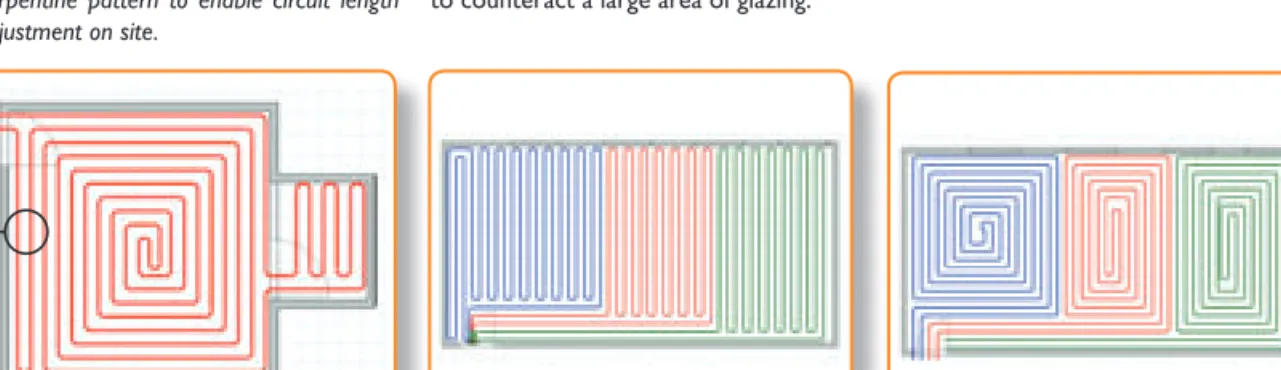
Different pipe patterns can be combined in irregular shaped rooms. In the below example the main area is a Counterflow pattern and then a Serpentine layout is used in the small ensuite area.
TIP: To reduce the chance of running out of pipe, the final part of the circuit in this example has been completed in a Serpentine pattern to enable circuit length adjustment on site.
In rooms requiring multiple circuit areas, both Counterflow and Serpentine layouts can be used to good effect. Typical examples are shown below with three circuits required that enter the room at the bottom left hand corner. It is important to choose a pattern suitable for the room. For example, in areas of high heat loss, pipes may need to be closer together at one end of the room to counteract a large area of glazing.
The JG Speedfit Technical Support Team can advise you on your specific project.
Dia 1 - Serpentine is a simple up & Diagram 2 Counterflo
Diagram 1— Serpen�ne is a simple
ARA
TION CONSIDERA
TIONS
wPREP
ARA
TION CONSIDERA
TIONS
TYPICAL PIPE LAYOUT USING COUNTERFLOW PIPE PATTERN
TYPICAL PIPE LAYOUT USING SERPENTINE PIPE PATTERN
ARA
TION CONSIDERA
TIONS
LAYING YOUR PIPE
STEP 1.Install Underfloor Heating Manifold.
STEP 4. Repeat the process for the next room.
STEP 3. To complete the loop, return pipe inside the exisiting pattern back to the manifold maintaining the pipe spacing (typically 200mm).
STEP 6. Continue the process for the remaining rooms, ensuring pipes are not crossed in the floor.
STEP 2. Working from left to right or right to
left, install first loop working into the centre of the room.
STEP 5. In rooms with more than one
circuit care should be taken to ensure enough room is left for flow and return runs back to the manifold.
STEP 1.Insulation depth and quality as required by design or building regulations, “whichever is greater” and to ensure that any downward heat loss from the Underfloor Heating does not exceed 10W/m2, in accordance with BSEN1264.
STEP 4.This vapour barrier will prevent the contamination of the insulation by the screed. It will also prevent liquid type screeds from flowing between gaps in the insulation and “floating” the boards during installation.
STEP 3. BS EN 1264 Part 4 requires a protective membrane placed over the insulation layer and it specifies Polyethylene film of at least 0.15mm thickness with 80mm overlaps or a similar product which performs the same function e.g. Aluminium Foil - fitted at the factory.
STEP 2.An expansion strip is required to accommodate the expansion which will occur within the screed as the result of it heating up. This expansion strip should be fitted round the perimeter of the room and taped to the membrane.
STEP 5.Screed is placed on top of the
pipe circuits. STEP 6.into consideration as part of the floor Screed depths need to be taken build thickness. (See page 20 for typical floor section).
Prepared floor insulation should be fitted to a flat sub-base. This is important as the sheet insulation needs to be fully supported for maximum strength. The joints should be securely taped over.
SCREEDING
The Screed should be laid as soon as possible after the pressure test and the system should be left under pressure during the screeding process. Cement, sand and fine concrete screeds should be designed and laid to the recommendations in BS 8204. Low thickness pumped screeds are available from specialist installers and work well with Underfloor Heating. Screed drying times will vary, typically 28 days for a sand/cement screed. Underfloor Heating systems should not be used to speed up the screed drying process.
Some buildings, especially older types may have a higher heat loss than the Underfloor Heating can provide. In this case there may be a need to increase the insulation and reduce heat loss of the building or supplementary heating should be considered.
PREPARING THE FLOORS IN SCREEDED AREAS
Preparation Considerations
PREP
ARA
TION CONSIDERA
ARA
TION CONSIDERA
THE UFH STAPLE SYSTEM
Pipe Installation
PIPE INST
ALLA
TION
Part No. Description
JGUFHEDGE 25 METRE ROLL
EDGE STRIP
Part No. Description
JGUFHGUN STAPLE GUN JGUFHSTAPLE PIPE STAPLES
PIPE STAPLES
PRODUCTS ESSENTIAL FOR THIS INSTALLATION
Part No. Description Size
15BPB-50C BARRIER PIPE 15MM X 50M 15BPB-100C BARRIER PIPE 15MM X 100M 15BPB-120C BARRIER PIPE 15MM X 120M 15BPB-150C BARRIER PIPE 15MM X 150M JG LAYFLAT® POLYBUTYLENE BARRIER PIPE
THINGS TO REMEMBER
• Insulation depth as required by design or building regulations to ensure that any downward heat loss does not exceed 10 watts per m/2 in accordance with BSEN1264.
• The overall quality and thickness of a sand and cement screed should meet the requirements of BS8204-1.
STEP 1.To prepare the floor, insulation should be fitted to a flat sub-base. The joints should also be taped and a membrane placed over the insulation.
STEP 4.Using the staple gun, fix the pipework to the installation in the desired pattern (see page 15 images on patterns of pipework). Starting the first circuit 75mm from the perimeter and staples should be approximately 500mm apart. More staples maybe needed on bends.
STEP 3. After establishing the area to be covered by the pipe circuit, connect to the manifold and start the circuit. If the circuit has to pass through other heated zones before reaching the zone it is intended to heat, conduit may be required.
STEP 6. Once the pipe circuit has been installed and pressure tested, the system should remain under pressure (6 bar) in order to help prevent the risk of any damage to the pipe while the screed is being applied. When applying the screed, care should be taken to ensure the screed is tightly compacted around the pipe ensuring no voids are present.
STEP 2. An expansion strip is required around the perimeter of the room to accommodate the expansion which will occur within the screed as a result of heating up. This should be fitted around the perimeter of the room and taped to the membrane.
STEP 5.When using the pipe, unroll it from the outside of the coil and do not try to uncoil it from the centre, this will make the process easier. Keeping the first run of pipe around the perimeter straight and using a gauge to keep the designed pipe centres even will also help the installation process.
STEP 2.
oll it fr
STEP 3. After STEP 1 e the floor
Using the screed as a heat diffuser, JG Speedfit pipe is secured with staples to rigid insulation placed over the concrete sub-floor. A variety of screeds can be used and are typically 65-75mm thick for sand-cement types or 40-50mm for liquid pumped screeds. The system is quick to install, cost effective, and can be easily adaptable to irregular room shapes. Floor coverings can be laid when the screed is fully cured.
INSTALLING THE UFH STAPLE SYSTEM
ALLA
THE MOUNTING RAIL
PRODUCTS ESSENTIAL FOR THIS INSTALLATION
Pipe Installation
PIPE INST
ALLA
TION
Part No. Description
JGUFHEDGE 25 METRE ROLL
EDGE STRIP
Part No. Description
JGUFHRAIL 2 METRE LONG JGUFHPIN RAIL PINS FOR ABOVE
MOUNTING RAIL
Part No. Description Size
15BPB-50C BARRIER PIPE 15MM X 50M 15BPB-100C BARRIER PIPE 15MM X 100M 15BPB-120C BARRIER PIPE 15MM X 120M 15BPB-150C BARRIER PIPE 15MM X 150M JG LAYFLAT® POLYBUTYLENE BARRIER PIPE
THINGS TO REMEMBER
• 1.5 to 2 linear metres of mounting rail per sq/m of floor area. 1 pack per 20sq/m. • Maximum circuit length 100m of 15mm pipe.
• Maximum coverage Approx. 100m centres 11 sq/m 200mm centres 20sq/m. • Maximum heat output for 200mm centres = 100Wsq/m.
• Recommended design flow temperature 50oC.
• Insulation depth as required by design or building regulations to ensure that any downward.
STEP 1. To prepare the floor, insulation should be fitted to a flat sub-base. The joints should be taped and membrane placed over the insulation.
STEP 4. The mounting rail has double sided tape, this may need to be supplemented with the use of JGUFHPIN depending on the adhesions of the installation.
STEP 3.After establishing the area to be covered by the circuit, connect to the manifold and start the circuit. If the circuit has to pass through other heated zones before reaching the zone it is intended to heat, conduit may be required.
STEP 6. A serpentine pattern is usually the most convenient to use with the mounting rail system. Ensure to allow enough space at the end of the circuits for the flow and return from the manifolds.
STEP 2. An expansion strip is required around the perimeter of the room to accommodate the expansion which will occur within the screed as a result of heating up. This should be fitted around the perimeter of the room and taped to the membrane.
STEP 5.The mounting rail is placed at about 750/800mm apart ensuring the slots are aligned neatly.
STEP 3. STEP 2.
STEP 5. The mounting rail is placed at
STEP 3. After establishing the ar STEP 3.
STEP 6. A serpentine pattern is usually the STEP 6.
STEP 1 e the floor STEP 2.STEP 2.
STEP 4.The mounting rail has double sided STEP 5.STEP 5.
Using the screed as a heat diffuser, Speedfit Pipe is secured to ‘Clip Rails’ on top of rigid insulation which is placed over the concrete sub-floor. A variety of screeds can be used and are typically 65-75mm thick for sand-cement types or 40-50mm for liquid pumped screeds. The system provides ready made pipe spacing, can be fixed to insulation which is too thin for staples, and is especially suitable for large regular shaped areas. Floor coverings can be laid when the screed is fully cured.
INSTALLING THE MOUNTING RAIL
ALLA
FLOOR PANEL SYSTEM
Pipe Installation
PIPE INST
ALLA
TION
Part No. Description Size
JGUFHTILE FLOOR TILE 1400MM X 800MM
FLOOR PANELS
Part No. Description
JGUFHEDGE 25 METRE ROLL
EDGE STRIP
PRODUCTS ESSENTIAL FOR THIS INSTALLATION
Part No. Description Size
15BPB-50C BARRIER PIPE 15MM X 50M 15BPB-100C BARRIER PIPE 15MM X 100M 15BPB-120C BARRIER PIPE 15MM X 120M 15BPB-150C BARRIER PIPE 15MM X 150M JG LAYFLAT® POLYBUTYLENE BARRIER PIPE
THINGS TO REMEMBER
• BS EN 1264-4 recommends that an expansion joint is constructed in stone and ceramic finished screeds for every 40m2 of floor area at a maximum length of 8m and an aspect ration of 2:1. An expansion joint is also required in long narrow areas such corridors etc. • Insulation depth as required by design or building regulations and to ensure that any downward heat loss does not exceed 10 watts per m/2 in accordance with BSEN1264.
STEP 1. Edge insulation should be installed around the perimeter of the room to accommodate expansion that will occur when the screed is heated up. It is good practice to seal the gap between the potential space between the expansion and the floor panel.
Speedfit Floor Panels make a simple grid to ensure quick and easy pipe laying and also provide a precise guide for the pipe, ensuring that minimum pipe bending radius is achieved. Suitable for use with cement screed (4:1 mix), pumped screed systems (anhydrite, etc.), fine or heavy concrete or polymer modified screeds.
STEP 4. When a pumped (liquid) screed is to be used it is essential that all of the panel joints are made correctly and that no panels are allowed to simply ‘butt-up’ as this may allow the screed to flow below the panels causing them to rise up.
STEP 3.The “egg box” sections of the panel clip firmly together to make a continuous seal. Floor panels should not be used at the base of a manifold as pipes need to be closer together than the floor panels will allow. Pipes around this area should be secured using pipe staples.
STEP 6.Once the pipe circuits have been installed and pressure tested, the system should remain under pressure (6 bar) in order to prevent the risk of any damage being caused to the pipe while the screed is being applied. When applying the screed cover, care should be taken to ensure that the screed is tightly compacted.
STEP 2. Floor panels should be fitted to a suitable flat sub base. Extra insulation maybe required to match design or building regulations and to ensure that any downward heat loss does not exceed 10 Watts m2 in accordance with BSEN1264.
STEP 5. Starting from a manifold, after establishing the area to be covered, unroll the pipe and push firmly into the gap between the egg box sections. Cover the designed area in the appropriate pattern and return the pipework to the manifold.
STEP 3. “egg x” of
1
INSTALLING FLOOR PANEL SYSTEM
ALLA
Timber and floating floors generally use heat spreader plates to transfer the heat from the pipes. There are many variations of these floor types and particular requirements should be discussed with our Technical Support Team.
Speedfit Pipe is installed into grooved aluminum plates which are first fixed from above in the case of traditional joists or from below when engineered I-Beam Joist systems are used. If the floor can be raised, floors can also be counter-battened to make installation even easier. Insulation is installed below the plates and it is important that the floor decking is in contact with the plate to maximise output.
SPREADER PLATES
UNDERFIT
SUSPENDED TIMBER FLOORS
Pipe Installation
PIPE INST
ALLA
ALLA
STEP 1. Plates need to be supported so that they sit level and make a good contact with the floor placed on them from above. Maintaining this contact is essential in producing good heat transfer.
STEP 4.Fix the plates to the top of the joists ensuring the fixing will not protrude and prevent the floor from having a good contact with the floor. 18mm staples fixed using an air stapler is the preferred method. Allow 300mm for pipe end returns and a 15mm gap between plates. Use a short length of pipe pressed into the grooves to line up the plates before fixing.
STEP 3. Battens should be fixed along the length of the joist, 15mm plus the depth of insulation board being used down from the top of the joists in order to support the insulation along its length. This will allow a 15mm gap between the surface of the insulation and the top of the joist.
STEP 6.Before fixing the floor to the joists it is recommended that a thin sheet of plastic is placed over the plates. This will act as a slip membrane to cut down expansion noises as the plates heat up and rub against the bottom of the finished floor.
STEP 2. Some time spent planning the installation will save time later and make installation easier. The main consideration is the amount of runs and the route those pipes will take from the manifold.
STEP 5.Run the pipework to the designed or desired pattern being careful to ensure the plates remain flush with the top of the joists. The pipework can enter the plate system at either end or in the centre, pipework can be cabled through joists or via grooves at the top of the joists. Consult building regulations to ensure compliance.
KEY DATA
Approx. Coverage Double Plates - 2 Plates per 1m21 box of 10 = 5m2
Recommended Design Temperature 60oC - Maximum Heat Output Approx. 70W/m
JG Speedfit’s plate system is designed for use in timber suspended or battened floors. The floor system uses aluminium single or double spreader plates to transmit the heat evenly across the finished floor surface.
They can be used as illustrated, below a floor supported on insulation. Alternatively, where there will be a secondary layer of floor placed above a sheet sub floor the plates can be sandwiched between the floor layers supported on battens. With a twin layer floor this second method is recommended as it removes a layer of resistence to heat transfer.
INSTALLING JG UFH PLATE SYSTEM - FROM ABOVE
PIPE INST
ALLA
TION
STEP 1.Planning is important to establish the areas that are to be fitted with plates and the route the pipework must take from the manifold to the area to be heated. Remember that the pipework can pass through the joists in the same way that the Heating and hot and cold pipes do. Make sure that any drilling zones are observed.
STEP 4.The pipework can start at either end or if needed in the middle of a run. Again this is usualy dictated by the joist layout. A serpentine pattern is usually best suited to this system, working out beforehand the path the pipework will take will make the installation process easier.
STEP 3. Take care to allow enough room at the ends for pipework returns and accommodate the designed spacing, this will typically be 200mm which is often dictated by the joist centres.
STEP 6.Once the pipework is installed and pressure tested, insulation can be fitted to prevent downwards heat loss.
STEP 2. Fixing the plates firmly to the underneath of the joists using screws, tacks or a suitable staple gun. Allow a 50mm gap between the plates, a straight length of pipework can be used to ensure the grooves are lined up.
STEP 5. Care needs to be taken when installing the pipework as kinking the pipe due to over bending or careless use will necessitate a new section of pipework. Unlike using a pipe in a screed that cannot be replaced if damaged, pipework used below joists can have fittings as part of the heating system as long as the normal operating temperatures are observed and access is provided in the unlikely event of a leak.
KEY DATA
Approx. Coverage - 4 Plates per 1m2
Recommended Design Temperature 60oC - Maximum Heat Output Approx. 70W/m
JG Plate from below system is intended for use with modern pre engineered joists.
As modern joists rely on the floor above being bonded and screwed to the joist’s top surface. Because of this the normal practice of fitting the plates onto the top of the joists is not available.
INSTALLING JG UFH PLATE SYSTEM - FROM BELOW
ALLA
STEP 1.JG ‘Underfit®’ is intended to be used below flooring and supported firmly in contact with the underside of the flooring. It is ideally suited to refurbishment projects. As with all Underfloor Heating systems additional insulation may be required to meet building requirements.
STEP 4.Grooves spaced at 200mm from centre of pipe, the boards can be sized to accommodate most joist centres. If the panel is too wide, trim the material evenly from both sides to ensure a snug fit.
STEP 3.Battens should be fixed along the length of the joist, 50mm down from the top of the joists in order to support the panels along its length. Good contact between the surface of the panel and the bottom of the flooring is essential in maximising the performance of this system.
STEP 2. Some time spent planning the installation will save time later and make installation easier. The main consideration is the amount of runs and the route these pipes will take from the manifold.
STEP 5. Pipework can enter the panel system at either end or even in the centre, pipework can be cabled through joists or via grooves at the top of the joists. Consult building regulations to ensure compliance.
STEP 6. Pipework can enter the panel system at either end or even in the centre, pipework can be cabled through joists or via grooves at the top of the joists. Consult building regulations to ensure compliance.
DATA - 50mm UNDERFIT® BOARD
Dimensions - 1200 x 350 x 50 mm
Materials - Expanded Polystyrene BS EN 13163
Compressive Strength - 100 (kPa) @ 10% compression Conductivity - 0.036 (W/mk)
Heat Output - Approx 50 - 60w/m2
Recommended Flow Temperature - 50 - 60oC
Pipe Centres - 200mm Maximum Circuit Length - 100m Typical Coverage per Loop - 15 - 20m2
Applications - New Build or renovation, single or multiple rooms
Floor Coverings - Tiles/slate,/ceramic etc. Carpet/Vinyl Laminate floors Natural wood
A grooved, foil faced insulation panel for installing 15mm Speedfit pipe over existing floor structures (between battens) or under the floor (between existing joists). The system is a suitable choice for both new build and renovation projects.
Similar to other JG Speedfit Underfloor Heating systems, a variety of floor coverings can be used.
INSTALLING JG UNDERFIT
®- JOISTS AND BATTENED FLOORS
Pipe Installation
PIPE INST
ALLA
ALLA
NOTE: In order to prevent movement and subsequent cracking, when planning to lay a tiled floor the following recommendations should be followed. A heavy lapped backer board should be used. The Overfit should be fitted to a flat surface giving sufficient support for the boards and intended use. Good building practice should be observed and the tile & backer board manufacturers recommendations should be followed.
RETROFIT (OVERFIT)
Pipe Installation
PIPE INST
ALLA
TION
THINGS TO REMEMBER Dimensions – 1250 x 600 x 25mm Board Heat Output – Approx 50-60 w/m2 Pipe Centres – 150mm Maximum Circuit length – 100mPart No. Description Size
JGUFHBOARD1 OVERFIT BOARD 1250MM X 600MM
OVERFIT® BOARD
Part No. Description
JGUFHEDGE 25 METRE ROLL
EDGE STRIP
PRODUCTS ESSENTIAL FOR THIS INSTALLATION
Part No. Description Size
15BPB-50C BARRIER PIPE 15MM X 50M 15BPB-100C BARRIER PIPE 15MM X 100M 15BPB-120C BARRIER PIPE 15MM X 120M 15BPB-150C BARRIER PIPE 15MM X 150M JG LAYFLAT® POLYBUTYLENE BARRIER PIPE
DATA - 25mm OVERFIT® BOARD
Dimensions - 1250 x 600 x 25mm
Materials - Extruded Polystyrene-XPS2 (BS EN 13164) Compressive Strength - 250 (kPa) @ 10% compression Conductivity - 0.029 (W/mk)
Heat Output - Approx 50 - 60w/m2
Recommended Flow Temperature - 50 - 60oC
Pipe Centres - 150mm
100
Floor Coverings
Tiles/slate/ceramic etc. - use with Knauff Brio Board or eqivalent.
Carpet/vinyl - use with suitable plywood covering. Laminate floors - use directly over insulation as floating floor.
STEP 4.Start laying the pipework by pressing it firmly into the grooves. Where the pipework is connected to the manifold there will be a need to use plain insulation and pipe staples to accommodate the closer pipe centres.
STEP 3. After placing the boards and ensuring they are flat and level and the joints are butted up firmly. Tape the joints using JGTAPE.
STEP 6.After installing the pipework JGTAPE can be placed over the end loops to prevent the pipework from becoming dislodged during the installation of the finished floor.
STEP 2.Plates need to be supported so that they sit level and make a good contact with the floor placed on them from above. Maintaining this contact is essential in producing good heat transfer.
STEP 5.Where the pipe changes direction cut the foil in the return loops using a craft knife to prevent damage to the board. This will ensure a tight fit for the pipework.
STEP
STEP 5. Where the pipe changes direction cut STEP 6. After installing the pipe ork JGTAPE STEP ork JGTAPE ork JGT
STEP 4. Start laying the pipet laying the pipet la ork b essing STEP 5.STEP 5.
STEP 1.The main consideration is the amount of runs and the route those pipes will take from the manifold. If more transit grooves are needed then the grooves at the opposite ends can be cut off and used. Where possible route pipes through rather than around walls and doorways to cut down on pipework congestion. When lining up panels use a short length of pipe placed in the grooves to align them together.
JG UFH Overfit® is a low profile System for new build or renovation projects.
JG Overfit® is a lightweight insulated panel with high compressive strength intended for use with lightweight floor coverings, e.g. laminate, engineered wood and carpet. Due to its ease of handling and cutting it is also suitable for larger areas and multiple room installations.
The installation uses 15mm pipe and 150mm centres for a highly responsive system.
INSTALLING THE JG OVERFIT
®SYSTEM
ALLA
The installation of the manifold is an integral stage of the process. The JG Speedfit Manifold kits are for use on underfloor heating or radiator systems. The Manifold consists of two rails, one for the flow and one for the return, complete with ball valves and drain / filling valves. JG Manifolds are complete with pre-fitted brackets and vibration isolation mounts.
THINGS TO REMEMBER
• Insulation depth as required by design or building regulations and to ensure that any downward heat loss does not exceed 10 watts per m/2 in accordance with BSEN1264.
• Decorator caps can be used for manual isolation of a circuit and will usually be replaced by Electro Mechanic Actuators for fully automatic control.
STEP 1.Fix the pre-assembled manifold to the wall, allowing enough height to accommodate the insulation and screed depth and also the pipe work and conduit elbows.
STEP 4.Run the pipework from the manifold to the room that is to be heated. Ensure that if the pipework is passing through other rooms that conduit is used to prevent the pipework influencing the heat in those rooms. Ensure the pipework is at least 75mm from the perimeter wall.
STEP 3.Connect the pipework to the manifold following the guidelines for fitting JG pipe and fitting. It is best to start from one end of the manifold and work to the other. The use of JG conduit elbows will make the process easier and neater and enable the conduit to be inserted into the socket end.
STEP 6.The designed temperature through the circuits is controlled by turning the blending valve knob to the desired temperature. STEP 2. Using the supplied washer fit the JG
control pack. Isolation valves fitted to the inlet side of this unit will be useful in the event of needing to change a pump or blending unit.
STEP 5.The flow meters at the top of the manifold give a visual indication of the amount of water flowing through each circuit. The amount of flow will depend on the length of circuit and the temperature drop required. Generally the shorter the circuit the more restriction will be needed; this is called balancing the system.
STEP flo of STEP 6.STEP 6.
1
INSTALLING THE MANIFOLD AND PUMP PACK
JG UFH Manifold & Pump Pack Installation
JG UFH MANIFOLD & PUMP P
ACK INST
ALLA
ACK INST
ALLA
At the heart of the JG Aura 230v range is once again our unique 4 in 1 JG Aura thermostat, providing combined control of UFH and radiators allowing simple installation of multi zone energy saving systems in new or retrofit projects. The thermostat can operate as a Programmable Room Thermostat, Group Control Thermostat, Group Thermostat and a Hot Water Timer.
To enable the Group Control functionality it is essential that a 0.5mm 2 core data cable is utilised within the wiring process. The Group Control Thermostat can control a variation of both digital thermostats and dial thermostats from one central location. The optional data cable will not be required if the thermostats are to be used as individual Programmable Room Thermostats.
The Group Control Thermostat can control up to eight thermostats plus a Hot Water Timer.
The unique JG Aura 4 in 1 wireless thermostat is designed to present wireless control of your underfloor heating system including unique wireless boiler communication when installing the JG Aura Boiler Receiver. The JG Aura wireless thermostat is designed to work with the JG Aura app when incorporating the internet hub, presenting you ultimate control of time and temperature for your underfloor heating and hot water wherever you are in the world. The stylish slim line thermostats offer touch sensitive control at your fingertips. Uniquely, the installer is presented with two options of powering the thermostat, using either batteries or simply mains powered. At the heart of the range is the unique JG Aura thermostat that can operate in 4 easily configured modes, Programmable Room Thermostat, Group Control Thermostat, Group Thermostat or Hot Water Timer and can be used as Programmable Room Thermostat or combined into groups allowing convenient group control of many functions from one central place.
For use with the JG Aura Wireless Range. The JG Aura App gives you the freedom to control your underfloor heating and hot water no matter where you are via smart phone, tablet or desktop computer. The easy to use interface and intuitive nature of the JG Aura app, makes control of your heating system completely accessible from anywhere and at any time that suits you.
For more information please visit www.speedfitUFH.co.uk
JG AURA 230V CONTROLS
JG AURA WIRELESS CONTROLS
JG APP CONTROL
Heating Controls - 3 Options
HEA
TING CONTR
TING CONTR
SL L N 1 2 + LIVE IN LIVE OUT SUPPLIED CABLES 230V TO UFH PUMP
UNDERFLOOR HEATING MANIFOLD
1.5MM2CABLE (INSTALLER SUPPLIED) 230V 1.5MM2CABLE
(INSTALLER SUPPLIED) 230V 1.5MM2CABLE (INSTALLER SUPPLIED) 230V 1.5MM2CABLE (INSTALLER SUPPLIED) OPTIONAL CYLINDER STAT LIVE IN LIVE OUT
COLOURS ARE INDICATIVE ONLY. EXTRA CONNECTIONS MAY BE REQUIRED AS PER MANUFACTURERS INSTRUCTIONS. EARTH AS REQUIRED. ZONE 1 SL N L SL N L SL N L SL N L SL N L SL N L SL N L GROUP 2 GROUP 1 N L + + + + - - - - + + + SLN L SL ZONE 2 FACTORY FITTED LINK
ZONE 3 ZONE 4 ZONE 5 ZONE 6 ZONE 7 ZONE 8
SL L N 1 2 + 2 1SL L N + + 2 1 SL L N + 2 1 SL L N + 2 1SL L 0.5MM2 CABLE (INSTALLER SUPPLIED) L N L N L N L N L N L N L N L N L N L N L N L N L N L N L N L N
1
FACTORY FITTED LINK FACTORY FITTED LINK HW CYLINDER THERMOSTAT HW MOTORISED VALVEHOT WATER
OPTIONAL OPTIONAL OPTIONAL OPTIONAL
OPTIONAL
ZONE 1 ZONE 2 ZONE 3 ZONE 4 ZONE 5 ZONE 6 ZONE 7 ZONE 8
UFH MOTORISED VALVE OVERHEAT
STAT
IN OUT BR EA NOR GR IN OUT LN EIN OUT BR EA N OR GR
UFH PUMP BOILER ENABLE IN OUT HEATING/ COOLING
8
7
8
5
8
3
SUPPLIED C2
HOT WATER TIMER PROGRAMMABLE
ROOM THERMOSTAT GROUP 2 CONTROL THERMOSTAT THERMOSTATGROUP 2 THERMOSTATGROUP 2 DIAL THERMOSTATGROUP 2
OPTIONAL FOR RADIA TIMER TER AATER W HOT
ROOM THERMOSTPROGRAMMABLEAATT GROUPTHERMOSTTA 2 CONTROLAATT
ROOM THERMOSTPROGRAMMABLE 2 CONTROLT THERMOSTGROUP 2AATT THERMOSTGROUP 2AATT DIAL THERMOST THERMOSTGROUP 2 2
8
+ 2 1 SLL N + 2 1 SL LL N + 2 1 SL L N + OPTIONAL 2 1SL L N + OPTIONAL 2 1 SL L N + + 2 1 SLSL L1
OPTIONAL ALLER SUPPLIED) (INST CABLE 2 230V 1.5MM OPTIONAL SUPPLIED)ALLER (INSTTCABLE 2 0.5MM OPTIONAL OPTIONAL OPTIONAL OPTIONAL ALLER SUPPLIED) (INST230V 1.5MMLIVE OUT LIVE IN
ALLER SUPPLIED)CABLE 2 230V 1.5MM ALLER SUPPLIED) (INST CABLE 2 230V 1.5MM REQUIRED. TH AS
EARACTURERS INSTRUC
MANUFFMAY BE REQUIRED AS PER
CONNECTIO . EXTRA YY. EXTRA
ONLCOLOURS ARE INDICAATTI
LIVE OUT
REQUIRED.
ACTURERS INSTRUCTIONS.AS PER
CONNECTIONS TIVE F GR OR N EA BR OUT IN OVERHEA E LV VAORISED HW MOT T AAT THERMOST HW CYLINDER
7
FITTED LINK Y R TO C A F ENABLE BOILER UFH PUMPE BREAN L N INOUT OUT IN TAT S T OVERHEAAT VA UFH MOT LINK FITTED CTORY A F LINK FITTED CTORY A F COOLINGTING/ HEAATING/OUT IN GR OR N E LV VAORISED UFH MOT8
3
LIVE OUT LIVE IN
L N SL L N SL N L N L ZONE 1 TER AATER W HOT
8
5
L N SL L N SL L N L N L N L N L ZONE 3 ZONE 2 SLNL SLNL N L N L N L N L ZONE 5 ZONE 4 SLNL SLNL SLNL N L N L N L N L ZONE 8 ZONE 7ZONE 6 ++GROUP++ 2-- - -GROUP+ N L N L + + 1 GROUP
CYLINDER STOPTIONAL OPTIONAL INDER STTAAATT ZONE 1 ZONE 2 ZONE 3 ZONE 4 ZONE 5 ZONE 6 ZONE 7 ZONE 8
SUPPLIED C SUPPLIED C
SUPPLIED CABLES
2
UNDERFLOOR HEANDERFLOOR HEAATING MANIFOLDTING TING MANIFOLD
OPTIONAL FOR RADIA OPTIONAL 1.5MM 230V ALLER SUPPLIED) (INST CABLE 2 1.5MM O UFH PUMP T 230V
HEA
TING CONTR
OLS
WIRING DIAGRAM - JG AURA 230V
Heating Controls
FUSE FUSE 230V 1.5MM2CABLE (INSTALLER SUPPLIED) 230V 1.5MM2CABLE (INSTALLER SUPPLIED) 2 GROUP 1 POWER +- - - - + + + + ZONE 8 SL L N 1 2 + + 2 1 SL L N + 2 1SL L N + 2 1 SL L N 0.5MM2 CABLE (INSTALLER SUPPLIED) L N L N E N L
OPTIONAL OPTIONAL OPTIONAL
8
4
SUPPLIED CABLE
2
13 AMP FUSED CONNECTION UNIT FUSED AT 3 AMPS
GROUP 2
DIAL THERMOSTAT DIAL THERMOSTATGROUP 1 CONTROLGROUP 1 THERMOSTAT
OPTIONAL PROGRAMMABLE ROOM THERMOSTAT
(RADIATORS)
OPTIONAL UFH ZONE VALVE
FOR RADIATORS GROUPS
THERMOST
DIAL THERMOSTGROUP 2 2 AATT DIAL THERMOSTGROUP 1 AATT OPTIONAL T AAT THERMOSTCONTROL 1 GROUP ORS) T (RADIAAT AATT ROOM THERMOSTTA PROGRAMMABLE OPTIONAL 2 1 SL + SLL N + 2 1 SL L N + 2 1SL L N + 2 1 SL L N OPTIONAL ALLER SUPPLIED) (INST230V 1.5MM SUPPLIED)ALLER (INSTCABLE 2 0.5MM OPTIONAL
ALLER SUPPLIED)CABLE 2 230V 1.5MM OPTIONAL OPTIONAL
8
FUSE FUSE4
-- + + GROUP 2 N L N L + + + 1 GROUP FUSE POWER L N E ZONE 8 SUPPLIED CABLE SUPPLIED C ALLER SUPPLIED) (INST CABLE 2 230V 1.5MMALLER SUPPLIED)CABLE
2
ALLER SUPPLIED) (INSTALLER SUPPLIED)
OPTIONAL
ORS GROUPS T
FOR RADIAA UFH ZONE V VALLVEV OPTIONALL UFH ZONE V
FUSED A
FUSED CONNECTION UNIT AMP
13
ORS GROUPSVE FUSED CONNECTION UNIT FUSED CONNECTION UNITFUSED A ATT 3 AMPS
JGWC meets the following EC directives:
• Electro-Magnetic compatability directive 2004/108/EC • Low voltage directive 2006/95/EC
• RoHS2 directive 2011/65/EU
Please leave these instructions with the end user where they should be kept in a safe place for future reference. For the latest PDF Instruction Manuals please go to www.speedfitUFH.co.uk 230v Dial Thermostat
Part No. JGSTAT1
230v Thermostat and Hot Water Part No.
JGSTAT2W
Part No. JGSTAT2B
1 x Wiring Diagram Screws and Plugs JGWC
Contents
These instructions are applicable to the Speedfit Aura model as stated above.
Warning
This product must be fitted by a competent person, and installation must comply with the guidance, standards and regulations applicable to the location where the product is installed. Failure to comply with the requirements of the relevant guidance, standards and regulations could lead to prosecution, injury or death.
Earthing/bonding of all field devices must be in accordance with the aforementioned guidance, standards and documentation. Always isolate the AC Mains supply before installing or working on any components that require 230v AC 50Hz supply. Isolation of the mains supply to the JG Wiring Centre via the local fused connection unit MAY NOT isolate all mains voltages present (such as boiler enable).
TING CONTR
SL L N 1 2 SL L N 1 2
LIVE IN LIVE OUT
ACTUATOR CABLES
230V TO UFH PUMP
UNDERFLOOR HEATING MANIFOLD
1.5MM2CABLE (INSTALLER SUPPLIED) 230V 1.5MM2CABLE (INSTALLER SUPPLIED) 230V 1.5MM2CABLE (INSTALLER SUPPLIED) 230V 1.5MM 2CABLE (INSTALLER SUPPLIED) OPTIONAL CYLINDER STAT OPTIONAL WIRELESS RECEIVER PART NO. JGBR OPTION 1 OPTION 2 LIVE IN LIVE OUT ZONE 1 ZONE 2 HW CYLINDER
THERMOSTAT HW MOTORISED VALVE OVERHEAT STAT UFH MOTORISED VALVE
IN OUTBR EA NOR GR IN OUT LN E IN OUTBR EA N OR GR
UFH PUMP BOILER ENABLE
ZONE 3 ZONE 4 ZONE 5 ZONE 6 ZONE 7
SL L N 1 2
L N L N L N L N L N L N
THERMOSTAT NEUTRAL CONNECTIONS THERMOSTAT LIVE CONNECTIONS
L N L N L N L N L N L N L N L N
MAINS POWERED
HOT WATER TIMER BATTERY POWEREDPROGRAMMABLE ROOM THERMOSTAT MAINS POWERED PROGRAMMABLE ROOM THERMOSTAT BATTERY POWERED PROGRAMMABLE ROOM THERMOSTAT MAINS POWERED PROGRAMMABLE ROOM THERMOSTAT BATTERY POWERED PROGRAMMABLE ROOM THERMOSTAT
1
7
4
5
9
FACTORY FITTED LINK FACTORY FITTED LINK FACTORY FITTED LINK3
ZONE 8 L N L N2
230V 1.5MM2CABLE (INSTALLER SUPPLIED)COLOURS ARE INDICATIVE ONLY. EXTRA CONNECTIONS
MAY BE REQUIRED AS PER MANUFACTURERS INSTRUCTIONS. EARTH AS REQUIRED. TIMER TER AATER W HOTMAINS POWERED
ROOM THERMOSTPROGRAMMABLE POWERED Y TTER BAATTER TIMER MAINS POWERED
ROOM THERMOSTPROGRAMMABLE MAINS POWERED T
AAT RMOSTA PROGRAMMABLE POWERED
ROOM THERMOSTPROGRAMMABLE TTER BAATTER T
AAT ROOM THERMOSTPROGRAMMABLE
MAINS POWERED
ROOM THERMOSTPROGRAMMABLE MAINS POWERED T
AAT ROOM THERMOSTPROGRAMMABLE
POWERED Y TTER T AAT OM THERMOSTTA PROGRAMMABLE MAINS POWERED
T AAT ROOM THERMOSTPROGRAMMABLE
POWERED Y TTER BAATTER 2 1 SL L N 2 1 SLSL L N 2 1 SL L N OPTION 2 OPTION 1
1
ALLER SUPPLIED) (INST 2 230V 1.5MMALLER SUPPLIED)CABLE (INSTALLER SUPPLIED)CABLE
2 230V 1.5MM ALLER SUPPLIED) (INST230V 1.5MM LIVE OUT LIVE IN
ALLER SUPPLIED)CABLE 2 230V 1.5MM
LIVE OUT
REQUIRED. TH AS
EARACTURERS INSTRUCTIONS.
MANUFFMAYY BE REQUIRED BE REQUIRED AS PER
CONNECTIO . EXTRAA CONNECTIONS YY. EXTRA
ONLCOLOURS ARE INDICAATIVE T
ALLER SUPPLIED) (INST CABLE
2 230V 1.5MM
REQUIRED.
ACTURERS INSTRUCTIONS.AS PER
CONNECTIONS TIVE ALLER SUPPLIED) GR OR N EA BR OUT IN OVERHEA E LV VAORISED HW MOT T AAT THERMOSTT HW CYLINDER
7
F ENABLEBOILER UFH PUMP N EA BR E L N INOUT OUT IN TAT S T OVERHEAT LV VA UFH MOT LINK FITTED CTORY A F GR OR E LVORISED4
LINK FITTED CTORY A F LINK FITTED CTORY A F3
LIVE OUT LIVE IN
N L N L
9
THERMOSTAATT NEUTRALN L N L N L N L
5
N L N L N L N L LIVE CONNECTIONS T AAT THERMOST CONNECTIONS RAL N L N L N L N L LIVE CONNECTIONS N L N LCYLOPTIONAL OPTIONAL INDER STTAAT ZONE 1 ZONE 2 ZONE 3 ZONE 4 ZONE 5 ZONE 6 ZONE 7 ZONE 8
NO. JGBR T AR P OR CABLES T ACTUAAT
2
UNDERFLOOR HEANDERFLOOR HEAATING MANIFOLDTING MANIFOLDTING MANIFOLD
2 1.5MM 230V ALLER SUPPLIED) (INST CABLE 2 O UFH PUMP T 230V
See Thermostat Instruction Manual for grouping options.
HEA
TING CONTR
OLS
WIRING DIAGRAM - JG AURA WIRELESS
Heating Controls
SL L N 1 2 2 1 SL L N FUSE FUSE 230V 1.5MM2CABLE (INSTALLER SUPPLIED) 230V 1.5MM2CABLE (INSTALLER SUPPLIED)
13 AMP FUSED CONNECTION UNIT FUSED AT 3 AMPS TTERY POWERED PROGRAMMABLE OOM THERMOSTAT MAINS POWERED PROGRAMMABLE ROOM THERMOSTAT BATTERY POWERED PROGRAMMABLE ROOM THERMOSTAT MAINS POWERED PROGRAMMABLE ROOM THERMOSTAT (RADIATOR ZONES)
2
10
3
SUPPLIED CABLEOPTIONAL UFH ZONE VALVE FOR RADIATORS GROUPS
ZONE 8 L N L N
2
POWER E N L T AAT OOM THERMOST PROGRAMMABLE TTERY POWEREDT AAT ROOM THERMOSTPROGRAMMABLE
MAINS POWERED
ROOM THERMOSTPROGRAMMABLE POWERED Y TTER BAATTER OR ZONES) T (RADIAAT ROOM THERMOSTPROGRAMMABLE
MAINS POWERED T AAT TA PROGRAMMABLE POWERED OR ZONES)AATT ROOM THERMOSTPROGRAMMABLE
MAINS POWERED
2
2 1 SL L N 2 1 SL L N ALLER SUPPLIED) (INST CABLE 2 230V 1.5MM3
FUSE10
N L N L FUSE L N EPOWER SUPPLIED CABLE ZONE 8 SUPPLIED CABLE ALLER SUPPLIED) (INST CABLE 2 230V 1.5MMALLER SUPPLIED)CABLE
2
ALLER SUPPLIED) (INSTALLER SUPPLIED)
OPTIONAL
ORS GROUPS T
FOR RADIA UFH ZONE V VALALLV OPTIONALL UFH ZONE V
FUSED A
FUSED CONNECTION UNIT AMP
13
ORS GROUPSVE FUSED CONNECTION UNIT FUSED CONNECTION UNITFUSED A ATT 3 AMPS
JGWCW meets the following EC directives:
• Electro-Magnetic compatability directive 2004/108/EC • Low voltage directive 2006/95/EC
• RoHS2 directive 2011/65/EU • R&TTE directive 1999/5/EC
1 x Wiring Diagram Screws and Plugs JGWCW
Contents
JG Coordinator
Part No. JGCO Wireless ThermostatsPart No.’s JGSTATW2W (230v) JGSTATW1W (Battery) Part No.’s JGSTATW2B (230v) JGSTATW1B (Battery) ptions.
Please leave these instructions with the end user where they should be kept in a safe place for future reference. For the PDF Instruction Manuals
please go to www.speedfitUFH.co.uk
These instructions are applicable to the Speedfit Aura model as stated above.
Warning
This product must be fitted by a competent person, and installation must comply with the guidance, standards and regulations applicable to the location where the product is installed. Failure to comply with the requirements of the relevant guidance, standards and regulations could lead to prosecution, injury or death.
Earthing/bonding of all field devices must be in accordance with the aforementioned guidance, standards and documentation. Always isolate the AC Mains supply before installing or working on any components that require 230v AC 50Hz supply. Isolation of the mains supply to the JG Wiring Centre via the local fused connection unit MAY NOT isolate all mains voltages present (such as boiler enable).