CHAPTER 16
STRUCTURAL DESIGN
SECTION 1601 GENERAL
1601.1 Scope.The provisions of this chapter shall govern the structural design of buildings, structures and portions thereof regulated by this code.
SECTION 1602
DEFINITIONS AND NOTATIONS
1602.1 Definitions.The following words and terms shall, for the purposes of this chapter, have the meanings shown herein.
ALLOWABLE STRESS DESIGN.A method of proportion-ing structural members, such that elastically computed stresses produced in the members bynominal loadsdo not exceed spec-ified allowable stresses (also called “working stress design”).
DEAD LOADS. The weight of materials of construction incorporated into the building, including but not limited to walls, floors, roofs, ceilings, stairways, built-in partitions, fin-ishes, cladding and other similarly incorporated architectural and structural items, and the weight of fixed service equipment, such as cranes, plumbing stacks and risers, electrical feeders, heating, ventilating and air-conditioning systems and automatic sprinkler systems.
DESIGN STRENGTH.The product of the nominal strength and a resistance factor (or strength reduction factor).
DIAPHRAGM.A horizontal or sloped system acting to trans-mit lateral forces to the vertical-resisting elements. When the term “diaphragm” is used, it shall include horizontal bracing systems.
Diaphragm, blocked. In light-frame construction, a dia-phragm in which all sheathing edges not occurring on a framing member are supported on and fastened to blocking.
Diaphragm boundary.In light-frame construction, a loca-tion where shear is transferred into or out of the diaphragm sheathing. Transfer is either to a boundary element or to another force-resisting element.
Diaphragm chord. A diaphragm boundary element per-pendicular to the applied load that is assumed to take axial stresses due to the diaphragm moment.
Diaphragm flexible.A diaphragm is flexible for the pur-pose of distribution of story shear and torsional moment where so indicated in Section 12.3.1 of ASCE 7, as modified in Section 1613.6.1.
Diaphragm, rigid.A diaphragm is rigid for the purpose of distribution of story shear and torsional moment when the lateral deformation of the diaphragm is less than or equal to two times the average story drift.
DURATION OF LOAD.The period of continuous applica-tion of a given load, or the aggregate of periods of intermittent applications of the same load.
ESSENTIAL FACILITIES.Buildings and other structures that are intended to remain operational in the event of extreme environmental loading from flood, wind, snow or earthquakes.
FABRIC PARTITION. A partition consisting of a finished surface made of fabric, without a continuous rigid backing, that is directly attached to a framing system in which the vertical framing members are spaced greater than 4 feet (1219 mm) on center.
FACTORED LOAD.The product of a nominal load and a load factor.
GUARD.See Section 1002.1.
IMPACT LOAD.The load resulting from moving machinery, elevators, craneways, vehicles and other similar forces and kinetic loads, pressure and possible surcharge from fixed or moving loads.
LIMIT STATE. A condition beyond which a structure or member becomes unfit for service and is judged to be no longer useful for its intended function (serviceability limit state) or to be unsafe (strength limit state).
LIVE LOADS.Those loads produced by the use and occu-pancy of the building or other structure and do not include con-struction or environmental loads such as wind load, snow load, rain load, earthquake load, flood load or dead load.
LIVE LOADS (ROOF). Those loads produced (1) during maintenance by workers, equipment and materials; and (2) during the life of the structure by movable objects such as planters and by people.
LOAD AND RESISTANCE FACTOR DESIGN (LRFD).A
method of proportioning structural members and their connec-tions using load and resistance factors such that no applicable limit state is reached when the structure is subjected to appro-priate load combinations. The term “LRFD” is used in the design of steel and wood structures.
LOAD EFFECTS. Forces and deformations produced in structural members by the applied loads.
LOAD FACTOR.A factor that accounts for deviations of the actual load from thenominal load, for uncertainties in the anal-ysis that transforms the load into a load effect, and for the prob-ability that more than one extreme load will occur simultaneously.
LOADS.Forces or other actions that result from the weight of building materials, occupants and their possessions, environ-mental effects, differential movement and restrained dimen-sional changes. Permanent loads are those loads in which variations over time are rare or of small magnitude, such as dead loads. All other loads are variable loads (see also “ Nomi-nal loads”).
NOMINAL LOADS.The magnitudes of the loads specified in this chapter (dead, live, soil, wind, snow, rain, flood and earth-quake).
➡
OCCUPANCY CATEGORY.A category used to determine structural requirements based on occupancy.
OTHER STRUCTURES. Structures, other than buildings, for which loads are specified in this chapter.
PANEL (PART OF A STRUCTURE).The section of a floor, wall or roof comprised between the supporting frame of two adjacent rows of columns and girders or column bands of floor or roof construction.
RESISTANCE FACTOR.A factor that accounts for devia-tions of the actual strength from the nominal strength and the manner and consequences of failure (also called “strength reduction factor”).
STRENGTH, NOMINAL. The capacity of a structure or member to resist the effects of loads, as determined by compu-tations using specified material strengths and dimensions and equations derived from accepted principles of structural mechanics or by field tests or laboratory tests of scaled models, allowing for modeling effects and differences between labora-tory and field conditions.
STRENGTH, REQUIRED.Strength of a member, cross sec-tion or connecsec-tion required to resist factored loads or related internal moments and forces in such combinations as stipulated by these provisions.
STRENGTH DESIGN.A method of proportioning structural members such that the computed forces produced in the mem-bers by factored loads do not exceed the member design strength [also called “load and resistance factor design” (LRFD)]. The term “strength design” is used in the design of concrete and masonry structural elements.
VEHICLE BARRIER SYSTEM.A system of building com-ponents near open sides of a garage floor or ramp or building walls that act as restraints for vehicles.
NOTATIONS. D = Dead load.
E = Combined effect of horizontal and vertical earthquake induced forces as defined in Section 12.4.2 of ASCE 7.
F = Load due to fluids with well-defined pressures and maximum heights.
Fa = Flood load in accordance with Chapter 5 of ASCE 7. H = Load due to lateral earth pressures, ground water
pressure or pressure of bulk materials.
L = Live load, except roof live load, including any per-mitted live load reduction.
Lr = Roof live load including any permitted live load
reduction.
R = Rain load.
S = Snow load.
T = Self-straining force arising from contraction or expansion resulting from temperature change, shrinkage, moisture change, creep in component
materials, movement due to differential settlement or combinations thereof.
W = Load due to wind pressure.
SECTION 1603
CONSTRUCTION DOCUMENTS
1603.1 General.Construction documentsshall show the size, section and relative locations of structural members with floor levels, column centers and offsets dimensioned. The design loads and other information pertinent to the structural design required by Sections 1603.1.1 through 1603.1.9 shall be indi-cated on theconstruction documents.
Exception: Construction documents for buildings con-structed in accordance with the conventional light-frame constructionprovisions of Section 2308 shall indicate the following structural design information:
1. Floor and roof live loads. 2. Ground snow load,Pg.
3. Basic wind speed (3-second gust), miles per hour (mph) (m/s) and wind exposure.
4. Seismic design categoryandsite class.
5. Flood design data, if located inflood hazard areas
established in Section 1612.3. 6. Design load-bearing values of soils.
1603.1.1 Floor live load.The uniformly distributed, con-centrated and impact floor live load used in the design shall be indicated for floor areas. Use of live load reduction in accordance with Section 1607.9 shall be indicated for each type of live load used in the design.
1603.1.2 Roof live load. The roof live load used in the design shall be indicated for roof areas (Section 1607.11).
1603.1.3 Roof snow load.The ground snow load,Pg, shall
be indicated. In areas where the ground snow load, Pg,
exceeds 10 pounds per square foot (psf) (0.479 kN/m2), the following additional information shall also be provided, regardless of whether snow loads govern the design of the roof:
1. Flat-roof snow load,Pf.
2. Snow exposure factor,Ce.
3. Snow load importance factor,I. 4. Thermal factor,Ct.
1603.1.4 Wind design data. The following information related to wind loads shall be shown, regardless of whether wind loads govern the design of the lateral-force-resisting system of the building:
1. Basic wind speed (3-second gust), miles per hour (m/s).
2. Wind importance factor,I, andoccupancy category. 3. Wind exposure. Where more than one wind exposure is utilized, the wind exposure and applicable wind direction shall be indicated.
4. The applicable internal pressure coefficient.
5. Components and cladding. The design wind pres-sures in terms of psf (kN/m2) to be used for the design of exterior component and cladding materials not spe-cifically designed by the registered design profes-sional.
1603.1.5 Earthquake design data.The following informa-tion related to seismic loads shall be shown, regardless of whether seismic loads govern the design of the lat-eral-force-resisting system of the building:
1. Seismic importance factor,I, andoccupancy cate-gory.
2. Mapped spectral response accelerations,SSandS1.
3. Site class.
4. Spectral response coefficients,SDSandSD1.
5. Seismic design category.
6. Basic seismic-force-resisting system(s). 7. Design base shear.
8. Seismic response coefficient(s),CS.
9. Response modification factor(s),R. 10. Analysis procedure used.
1603.1.6 Geotechnical information. The design load-bearing values of soils shall be shown on theconstruction documents.
1603.1.7 Flood design data.For buildings located in whole or in part inflood hazard areasas established in Section 1612.3, the documentation pertaining to design, if required in Section 1612.5, shall be included and the following infor-mation, referenced to the datum on the community’s Flood Insurance Rate Map (FIRM), shall be shown, regardless of whether flood loads govern the design of the building:
1. In flood hazard areas not subject to high-velocity wave action, the elevation of the proposed lowest floor, including the basement.
2. In flood hazard areas not subject to high-velocity wave action, the elevation to which any nonresiden-tial building will be dry floodproofed.
3. Inflood hazard areassubject to high-velocity wave action, the proposed elevation of the bottom of the lowest horizontal structural member of the lowest floor, including the basement.
1603.1.8 Special loads.Special loads that are applicable to the design of the building, structure or portions thereof shall be indicated along with the specified section of this code that addresses the special loading condition.
1603.1.9 Systems and components requiring special inspections for seismic resistance. Construction docu-mentsor specifications shall be prepared for those systems and components requiring special inspection for seismic resistance as specified in Section 1707.1 by theregistered design professionalresponsible for their design and shall be submitted for approval in accordance with Section 107.1.
Reference to seismic standards in lieu of detailed drawings is acceptable.
SECTION 1604
GENERAL DESIGN REQUIREMENTS
1604.1 General.Building, structures and parts thereof shall be designed and constructed in accordance with strength design,
load and resistance factor design, allowable stress design, empirical design or conventional construction methods, as per-mitted by the applicable material chapters.
1604.2 Strength. Buildings and other structures, and parts thereof, shall be designed and constructed to support safely the factored loads in load combinations defined in this code with-out exceeding the appropriate strength limit states for the mate-rials of construction. Alternatively, buildings and other structures, and parts thereof, shall be designed and constructed to support safely the nominal loads in load combinations defined in this code without exceeding the appropriate speci-fied allowable stresses for the materials of construction.
Loads and forces for occupancies or uses not covered in this chapter shall be subject to the approval of thebuilding official.
1604.3 Serviceability. Structural systems and members thereof shall be designed to have adequate stiffness to limit deflections and lateral drift. See Section 12.12.1 of ASCE 7 for drift limits applicable to earthquake loading.
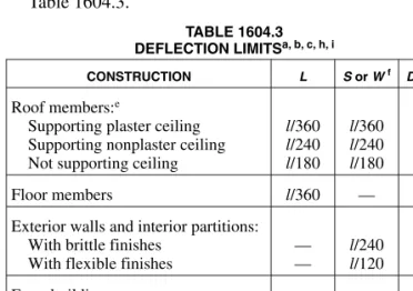
1604.3.1 Deflections.The deflections of structural mem-bers shall not exceed the more restrictive of the limitations of Sections 1604.3.2 through 1604.3.5 or that permitted by Table 1604.3.
TABLE 1604.3 DEFLECTION LIMITSa, b, c, h, i
CONSTRUCTION L S or Wf D + Ld, g
Roof members:e
Supporting plaster ceiling Supporting nonplaster ceiling Not supporting ceiling
l/360 l/240 l/180 l/360 l/240 l/180 l/240 l/180 l/120 Floor members l/360 — l/240
Exterior walls and interior partitions: With brittle finishes
With flexible finishes
— — l/240 l/120 — — Farm buildings — — l/180 Greenhouses — — l/120
For SI: 1 foot = 304.8 mm.
a. For structural roofing and siding made of formed metal sheets, the total load deflection shall not exceedl/60. For secondary roof structural members sup-porting formed metal roofing, the live load deflection shall not exceedl/150. For secondary wall members supporting formed metal siding, the design wind load deflection shall not exceedl/90. For roofs, this exception only applies when the metal sheets have no roof covering.
b. Interior partitions not exceeding 6 feet in height and flexible, folding and portable partitions are not governed by the provisions of this section. The deflection criterion for interior partitions is based on the horizontal load defined in Section 1607.13.
c. See Section 2403 for glass supports.
(Table notes continued)
d. For wood structural members having a moisture content of less than 16 per-cent at time of installation and used under dry conditions, the deflection resulting fromL+ 0.5Dis permitted to be substituted for the deflection resulting fromL+D.
e. The above deflections do not ensure against ponding. Roofs that do not have sufficient slope or camber to assure adequate drainage shall be investigated for ponding. See Section 1611 for rain and ponding requirements and Sec-tion 1503.4 for roof drainage requirements.
f. The wind load is permitted to be taken as 0.7 times the “component and clad-ding” loads for the purpose of determining deflection limits herein. g. For steel structural members, the dead load shall be taken as zero. h. For aluminum structural members or aluminum panels used in skylights and
sloped glazing framing, roofs or walls of sunroom additions or patio covers, not supporting edge of glass or aluminum sandwich panels, the total load deflection shall not exceedl/60. For continuous aluminum structural mem-bers supporting edge of glass, the total load deflection shall not exceedl/175 for each glass lite orl/60 for the entire length of the member, whichever is more stringent. For aluminum sandwich panels used in roofs or walls of sun-room additions or patio covers, the total load deflection shall not exceed l/120.
i. For cantilever members,lshall be taken as twice the length of the cantilever.
1604.3.2 Reinforced concrete. The deflection of rein-forced concrete structural members shall not exceed that permitted by ACI 318.
1604.3.3 Steel.The deflection of steel structural members shall not exceed that permitted by AISC 360, AISI S100, ASCE 3, ASCE 8, SJI CJ-1.0, SJI JG-1.1, SJI K-1.1 or SJI LH/DLH-1.1, as applicable.
1604.3.4 Masonry.The deflection of masonry structural members shall not exceed that permitted by TMS 402/ACI 530/ASCE 5.
1604.3.5 Aluminum. The deflection of aluminum struc-tural members shall not exceed that permitted by AA ADM1.
1604.3.6 Limits. Deflection of structural members over span,l, shall not exceed that permitted by Table 1604.3.
1604.4 Analysis.Load effectson structural members and their connections shall be determined by methods of structural anal-ysis that take into account equilibrium, general stability, geo-metric compatibility and both short- and long-term material properties.
Members that tend to accumulate residual deformations under repeated service loads shall have included in their analy-sis the added eccentricities expected to occur during their ser-vice life.
Any system or method of construction to be used shall be based on a rational analysis in accordance with well-estab-lished principles of mechanics. Such analysis shall result in a system that provides a complete load path capable of transfer-ring loads from their point of origin to the load-resisting ele-ments.
The total lateral force shall be distributed to the various verti-cal elements of the lateral-force-resisting system in proportion to their rigidities, considering the rigidity of the horizontal bracing system or diaphragm. Rigid elements assumed not to be a part of the lateral-force-resisting system are permitted to be incorporated into buildings provided their effect on the action of the system is considered and provided for in the design. Except where diaphragms are flexible, or are permitted to be analyzed as flexible, provisions shall be made for the increased forces induced on resisting elements of the structural
system resulting from torsion due to eccentricity between the center of application of the lateral forces and the center of rigid-ity of the lateral-force-resisting system.
Every structure shall be designed to resist the overturning effects caused by the lateral forces specified in this chapter. See Section 1609 for wind loads, Section 1610 for lateral soil loads and Section 1613 for earthquake loads.
1604.5 Occupancy category. Each building and structure shall be assigned anoccupancy categoryin accordance with Table 1604.5.
1604.5.1 Multiple occupancies.Where a building or struc-ture is occupied by two or more occupancies not included in the sameoccupancy category, it shall be assigned the classi-fication of the highestoccupancy categorycorresponding to the various occupancies. Where buildings or structures have two or more portions that are structurally separated, each portion shall be separately classified. Where a separated portion of a building or structure provides required access to, required egress from or shares life safety components with another portion having a higheroccupancy category, both portions shall be assigned to the higheroccupancy cat-egory.
1604.6 In-situ load tests.Thebuilding officialis authorized to require an engineering analysis or a load test, or both, of any construction whenever there is reason to question the safety of the construction for the intended occupancy. Engineering anal-ysis and load tests shall be conducted in accordance with Sec-tion 1714.
1604.7 Preconstruction load tests.Materials and methods of construction that are not capable of being designed by
approvedengineering analysis or that do not comply with the applicable material design standards listed in Chapter 35, or alternative test procedures in accordance with Section 1712, shall be load tested in accordance with Section 1715.
1604.8 Anchorage.
1604.8.1 General.Anchorage of the roof to walls and col-umns, and of walls and columns to foundations, shall be provided to resist the uplift and sliding forces that result from the application of the prescribed loads.
1604.8.2 Walls.Walls shall be anchored to floors, roofs and other structural elements that provide lateral support for the wall. Such anchorage shall provide a positive direct connec-tion capable of resisting the horizontal forces specified in this chapter but not less than the minimum strength design horizontal force specified in Section 11.7.3 of ASCE 7, sub-stituted for “E” in the load combinations of Section 1605.2 or 1605.3. Concrete and masonry walls shall be designed to resist bending between anchors where the anchor spacing exceeds 4 feet (1219 mm). Required anchors in masonry walls of hollow units or cavity walls shall be embedded in a reinforced grouted structural element of the wall. See Sec-tions 1609 for wind design requirements and 1613 for earth-quake design requirements.
1604.8.3 Decks.Where supported by attachment to an exte-rior wall, decks shall be positively anchored to the primary structure and designed for both vertical and lateral loads as applicable. Such attachment shall not be accomplished by
the use of toenails or nails subject to withdrawal. Where positive connection to the primary building structure cannot be verified during inspection, decks shall be self-support-ing. Connections of decks with cantilevered framing mem-bers to exterior walls or other framing memmem-bers shall be designed for both of the following:
1. The reactions resulting from the dead load and live load specified in Table 1607.1, or the snow load spec-ified in Section 1608, in accordance with Section 1605, acting on all portions of the deck.
2. The reactions resulting from the dead load and live load specified in Table 1607.1, or the snow load spec-ified in Section 1608, in accordance with Section 1605, acting on the cantilevered portion of the deck,
and no live load or snow load on the remaining por-tion of the deck.
1604.9 Counteracting structural actions.Structural mem-bers, systems, components and cladding shall be designed to resist forces due to earthquake and wind, with consideration of overturning, sliding and uplift. Continuous load paths shall be provided for transmitting these forces to the foundation. Where sliding is used to isolate the elements, the effects of friction between sliding elements shall be included as a force.
1604.10 Wind and seismic detailing.Lateral-force-resisting systems shall meet seismic detailing requirements and limita-tions prescribed in this code and ASCE 7, excluding Chapter 14 and Appendix 11A, even when windload effectsare greater than seismicload effects.
TABLE 1604.5
OCCUPANCY CATEGORY OF BUILDINGS AND OTHER STRUCTURES OCCUPANCY
CATEGORY NATURE OF OCCUPANCY
I
Buildings and other structures that represent a low hazard to human life in the event of failure, including but not limited to:
• Agricultural facilities.
• Certain temporary facilities.
• Minor storage facilities.
II Buildings and other structures except those listed in Occupancy Categories I, III and IV
III
Buildings and other structures that represent a substantial hazard to human life in the event of failure, including but not limited to:
• Buildings and other structures whose primary occupancy is public assembly with an occupant load greater than 300.
• Buildings and other structures containing elementary school, secondary school or day care facilities with an occupant load greater than 250.
• Buildings and other structures containing adult education facilities, such as colleges and universities, with an occupant load greater than 500.
• Group I-2 occupancies with an occupant load of 50 or more resident patients but not having surgery or emergency treatment facilities.
• Group I-3 occupancies.
• Any other occupancy with an occupant load greater than 5,000a.
• Power-generating stations, water treatment facilities for potable water, waste water treatment facilities and other pub-lic utility facilities not included in Occupancy Category IV.
• Buildings and other structures not included in Occupancy Category IV containing sufficient quantities of toxic or ex-plosive substances to be dangerous to the public if released.
IV
Buildings and other structures designated as essential facilities, including but not limited to:
• Group I-2 occupancies having surgery or emergency treatment facilities.
• Fire, rescue, ambulance and police stations and emergency vehicle garages.
• Designated earthquake, hurricane or other emergency shelters.
• Designated emergency preparedness, communications and operations centers and other facilities required for emer-gency response.
• Power-generating stations and other public utility facilities required as emergency backup facilities for Occupancy Category IV structures.
• Structures containing highly toxic materials as defined by Section 307 where the quantity of the material exceeds the maximum allowable quantities of Table 307.1(2).
• Aviation control towers, air traffic control centers and emergency aircraft hangars.
• Buildings and other structures having critical national defense functions.
• Water storage facilities and pump structures required to maintain water pressure for fire suppressionb.
a. For purposes of occupant load calculation, occupancies required by Table 1004.1.1 to use gross floor area calculations shall be permitted to use net floor areas to determine the total occupant load.
SECTION 1605 LOAD COMBINATIONS
1605.1 General.Buildings and other structures and portions thereof shall be designed to resist:
1. The load combinations specified in Section 1605.2, 1605.3.1 or 1605.3.2,
2. The load combinations specified in Chapters 18 through 23, and
3. The load combinations with overstrength factor speci-fied in Section 12.4.3.2 of ASCE 7 where required by Section 12.2.5.2, 12.3.3.3 or 12.10.2.1 of ASCE 7. With the simplified procedure of ASCE 7 Section 12.14, the load combinations with overstrength factor of Section 12.14.3.2 of ASCE 7 shall be used.
Applicable loads shall be considered, including both earth-quake and wind, in accordance with the specified load combi-nations. Each load combination shall also be investigated with one or more of the variable loads set to zero.
Where the load combinations with overstrength factor in Section 12.4.3.2 of ASCE 7 apply, they shall be used as fol-lows:
1. The basic combinations for strength design with overstrength factor in lieu of Equations 16-5 and 16-7 in Section 1605.2.1.
2. The basic combinations forallowable stress designwith overstrength factor in lieu of Equations 16-12, 16-13 and 16-15 in Section 1605.3.1.
3. The basic combinations forallowable stress designwith overstrength factor in lieu of Equations 16-20 and 16-21 in Section 1605.3.2.
1605.1.1 Stability.Regardless of which load combinations are used to design for strength, where overall structure sta-bility (such as stasta-bility against overturning, sliding, or buoy-ancy) is being verified, use of the load combinations specified in Section 1605.2 or 1605.3 shall be permitted. Where the load combinations specified in Section 1605.2 are used, strength reduction factors applicable to soil resis-tance shall be provided by aregistered design professional. The stability of retaining walls shall be verified in accor-dance with Section 1807.2.3.
1605.2 Load combinations using strength design or load and resistance factor design.
1605.2.1 Basic load combinations.Where strength design orload and resistance factor designis used, structures and portions thereof shall resist the most critical effects from the following combinations of factored loads:
1.4(D+F) (Equation 16-1) 1.2(D+F+T) + 1.6(L+H) + 0.5(LrorSorR) (Equation 16-2) 1.2D+ 1.6(LrorSorR) + (f1Lor 0.8W) (Equation 16-3) 1.2D+ 1.6W+f1L+ 0.5(LrorSorR) (Equation 16-4) 1.2D+ 1.0E+f1L+f2S (Equation 16-5) 0.9D+ 1.6W+ 1.6H (Equation 16-6) 0.9D+ 1.0E+ 1.6H (Equation 16-7) where:
f1 = 1 for floors in places of public assembly, for live loads in excess of 100 pounds per square foot (4.79 kN/m2), and for parking garage live load, and
= 0.5 for other live loads.
f2 = 0.7 for roof configurations (such as saw tooth) that do not shed snow off the structure, and
= 0.2 for other roof configurations.
Exception:Where other factored load combinations are specifically required by the provisions of this code, such combinations shall take precedence.
1605.2.2 Flood loads.Where flood loads,Fa, are to be
con-sidered in the design, the load combinations of Section 2.3.3 of ASCE 7 shall be used.
1605.3 Load combinations using allowable stress design. 1605.3.1 Basic load combinations.Whereallowable stress design(working stress design), as permitted by this code, is used, structures and portions thereof shall resist the most critical effects resulting from the following combinations of loads: D+F (Equation 16-8) D+H+F+L+T (Equation 16-9) D+H+F+ (LrorSorR) (Equation 16-10) D+H+F+ 0.75(L+T) + 0.75(LrorSorR) (Equation 16-11) D+H+F+ (Wor 0.7E) (Equation 16-12) D+H+F+ 0.75(Wor 0.7E) + 0.75L+ 0.75(LrorSorR) (Equation 16-13) 0.6D+W+H (Equation 16-14) 0.6D+ 0.7E+H (Equation 16-15) Exceptions:
1. Crane hook loads need not be combined with roof live load or with more than three-fourths of the snow load or one-half of the wind load.
2. Flat roof snow loads of 30 psf (1.44 kN/m2) or less and roof live loads of 30 psf (1.44 kN/m2) or less need not be combined with seismic loads. Where flat roof snow loads exceed 30 psf (1.44 kN/m2), 20 percent shall be combined with seismic loads.
1605.3.1.1 Stress increases. Increases in allowable stresses specified in the appropriate material chapter or the referenced standards shall not be used with the load combinations of Section 1605.3.1, except that increases shall be permitted in accordance with Chapter 23.
1605.3.1.2 Flood loads.Where flood loads,Fa, are to be
considered in design, the load combinations of Section 2.4.2 of ASCE 7 shall be used.
1605.3.2 Alternative basic load combinations.In lieu of the basic load combinations specified in Section 1605.3.1, struc-tures and portions thereof shall be permitted to be designed for the most critical effects resulting from the following combina-tions. When using these alternative basic load combinations that include wind or seismic loads, allowable stresses are per-mitted to be increased or load combinations reduced where permitted by the material chapter of this code or the referenced standards. For load combinations that include the counteract-ing effects of dead and wind loads, only two-thirds of the mini-mum dead load likely to be in place during a design wind event shall be used. Where wind loads are calculated in accordance with Chapter 6 of ASCE 7, the coefficientωin the following equations shall be taken as 1.3. For other wind loads,ωshall be taken as 1. When using these alternative load combinations to evaluate sliding, overturning and soil bearing at the soil-struc-ture interface, the reduction of foundation overturning from Section 12.13.4 in ASCE 7 shall not be used. When using these alternative basic load combinations for proportioning founda-tions for loadings, which include seismic loads, the vertical seismicload effect,Ev,in Equation 12.4-4 of ASCE 7 is
permit-ted to be taken equal to zero.
D+L+ (LrorSorR) (Equation 16-16) D+L+ (ωW) (Equation 16-17) D+L+ωW+S/2 (Equation 16-18) D+L+S+ωW/2 (Equation 16-19) D+L+S+E/1.4 (Equation 16-20) 0.9D+E/1.4 (Equation 16-21) Exceptions:
1. Crane hook loads need not be combined with roof live loads or with more than three-fourths of the snow load or one-half of the wind load.
2. Flat roof snow loads of 30 psf (1.44 kN/m2) or less and roof live loads of 30 psf (1.44 kN/m2) or less need not be combined with seismic loads. Where flat roof snow loads exceed 30 psf (1.44 kN/m2), 20 percent shall be combined with seismic loads.
1605.3.2.1 Other loads.WhereF,HorTare to be con-sidered in the design, each applicable load shall be added to the combinations specified in Section 1605.3.2.
1605.4 Heliports and helistops.Heliport and helistop landing areas shall be designed for the following loads, combined in accordance with Section 1605:
1. Dead load,D, plus the gross weight of the helicopter,Dh,
plus snow load,S.
2. Dead load,D, plus two single concentrated impact loads,
L, approximately 8 feet (2438 mm) apart applied any-where on the touchdown pad (representing each of the helicopter’s two main landing gear, whether skid type or wheeled type), having a magnitude of 0.75 times the gross weight of the helicopter. Both loads acting together total 1.5 times the gross weight of the helicopter.
3. Dead load,D, plus a uniform live load,L, of 100 psf (4.79 kN/m2).
Exception: Landing areas designed for helicopters with gross weights not exceeding 3,000 pounds (13.34 kN) in accordance with Items 1 and 2 shall be permitted to be designed using a 40 psf (1.92 kN/m2) uniform live load in Item 3, provided the landing area is identified with a 3,000-pound (13.34 kN) weight limitation. This 40-psf (1.92 kN/m2) uniform live load shall not be reduced. The landing area weight limitation shall be indicated by the numeral “3” (kips) located in the bottom right corner of the landing area as viewed from the primary approach path. The indication for the landing area weight limitation shall be a minimum 5 feet (1524 mm) in height.
SECTION 1606 DEAD LOADS
1606.1 General.Dead loads are those loads defined in Section 1602.1. Dead loads shall be considered permanent loads.
1606.2 Design dead load.For purposes of design, the actual weights of materials of construction and fixed service equip-ment shall be used. In the absence of definite information, val-ues used shall be subject to the approval of thebuilding official.
SECTION 1607 LIVE LOADS
1607.1 General.Live loads are those loads defined in Section 1602.1.
1607.2 Loads not specified.For occupancies or uses not des-ignated in Table 1607.1, the live load shall be determined in accordance with a methodapprovedby thebuilding official.
1607.3 Uniform live loads.The live loads used in the design of buildings and other structures shall be the maximum loads expected by the intended use or occupancy but shall in no case be less than the minimum uniformly distributed unit loads required by Table 1607.1.
1607.4 Concentrated loads.Floors and other similar surfaces shall be designed to support the uniformly distributed live loads prescribed in Section 1607.3 or the concentrated load, in pounds (kilonewtons), given in Table 1607.1, whichever pro-duces the greaterload effects. Unless otherwise specified, the indicated concentration shall be assumed to be uniformly dis-tributed over an area 21/
2feet by 21/2feet (0.76 m by 0.76 m) [61/
4square feet (0.58 m2)] and shall be located so as to produce the maximumload effectsin the structural members.
1607.5 Partition loads.In office buildings and in other build-ings where partition locations are subject to change, provisions for partition weight shall be made, whether or not partitions are shown on theconstruction documents, unless the specified live load exceeds 80 psf (3.83 kN/m2). The partition load shall not be less than a uniformly distributed live load of 15 psf (0.72 kN/m2).
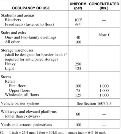
TABLE 1607.1
MINIMUM UNIFORMLY DISTRIBUTED LIVE LOADS,Lo, AND
MINIMUM CONCENTRATED LIVE LOADSg
OCCUPANCY OR USE
UNIFORM (psf)
CONCENTRATED (lbs.)
1. Apartments (see residential) — —
2. Access floor systems Office use Computer use 50 100 2,000 2,000
3. Armories and drill rooms 150 —
4. Assembly areas and theaters Fixed seats (fastened to floor) Follow spot, projections and control
rooms Lobbies Movable seats Stages and platforms Other assembly areas
60 50 100 100 125 100 —
5. Balconies (exterior) and decksh Same as occupancy served — 6. Bowling alleys 75 — 7. Catwalks 40 300 8. Cornices 60 —
9. Corridors, except as otherwise indicated 100 —
10. Dance halls and ballrooms 100 —
11. Dining rooms and restaurants 100 —
12. Dwellings (see residential) — —
13. Elevator machine room grating
(on area of 4 in2) — 300
14. Finish light floor plate construction (on area of 1 in2)
—
200 15. Fire escapes
On single-family dwellings only
100
40 —
16. Garages (passenger vehicles only) Trucks and buses
40 Note a
See Section 1607.6 17. Grandstands
(see stadium and arena bleachers) — — 18. Gymnasiums, main floors and balconies 100 — 19. Handrails, guards and grab bars See Section 1607.7 20. Hospitals
Corridors above first floor Operating rooms, laboratories Patient rooms 80 60 40 1,000 1,000 1,000
21. Hotels (see residential) — —
22. Libraries
Corridors above first floor Reading rooms Stack rooms 80 60 150b 1,000 1,000 1,000 continued TABLE 1607.1—continued
MINIMUM UNIFORMLY DISTRIBUTED LIVE LOADS,Lo, AND
MINIMUM CONCENTRATED LIVE LOADSg
OCCUPANCY OR USE UNIFORM (psf) CONCENTRATED (lbs.) 23. Manufacturing Heavy Light 250 125 3,000 2,000 24. Marquees 75 — 25. Office buildings
Corridors above first floor File and computer rooms shall be
designed for heavier loads based on anticipated occupancy Lobbies and first-floor corridors Offices 80 — 100 50 2,000 — 2,000 2,000 26. Penal institutions Cell blocks Corridors 40 100 — 27. Residential
One- and two-family dwellings Uninhabitable attics without storagei Uninhabitable attics with limited
storagei, j, k
Habitable attics and sleeping areas All other areas
Hotels and multifamily dwellings Private rooms and corridors
serving them
Public rooms and corridors serving them 10 20 30 40 40 100 —
28. Reviewing stands, grandstands and
bleachers Note c
29. Roofs
All roof surfaces subject to maintenance workers
Awnings and canopies
Fabric construction supported by a lightweight rigid skeleton structure All other construction
Ordinary flat, pitched, and curved roofs Primary roof members, exposed to a
work floor
Single panel point of lower chord of roof trusses or any point along primary structural members supporting roofs:
Over manufacturing, storage ware-houses, and repair garages All other occupancies
Roofs used for other special purposes Roofs used for promenade purposes Roofs used for roof gardens or
assembly purposes 5 nonreducible 20 20 Note 1 60 100 300 2,000 300 Note 1 30. Schools Classrooms
Corridors above first floor First-floor corridors 40 80 100 1,000 1,000 1,000 31. Scuttles, skylight ribs and accessible
ceilings — 200
32. Sidewalks, vehicular driveways and
yards, subject to trucking 250d 8,000e
33. Skating rinks 100 —
continued
➡
TABLE 1607.1—continued
MINIMUM UNIFORMLY DISTRIBUTED LIVE LOADS,Lo,AND
MINIMUM CONCENTRATED LIVE LOADSg
OCCUPANCY OR USE
UNIFORM (psf)
CONCENTRATED (lbs.)
34. Stadiums and arenas Bleachers
Fixed seats (fastened to floor)
100c
60c —
35. Stairs and exits
One- and two-family dwellings All other
40 100
Note f
36. Storage warehouses
(shall be designed for heavier loads if required for anticipated storage) Heavy Light 250 125 37. Stores Retail First floor Upper floors Wholesale, all floors
100 75 125 1,000 1,000 1,000 38. Vehicle barrier systems See Section 1607.7.3 39. Walkways and elevated platforms
(other than exitways) 60 —
40. Yards and terraces, pedestrians 100 —
For SI: 1 inch = 25.4 mm, 1 foot = 304.8 mm, 1 square inch = 645.16 mm2,
1 square foot = 0.0929 m2,
1 pound per square foot = 0.0479 kN/m2, 1 pound = 0.004448 kN,
a. Floors in garages or portions of buildings used for the storage of motor vehicles shall be designed for the uniformly distributed live loads of Table 1607.1 or the following con-centrated loads: (1) for garages restricted to passenger vehicles accommodating not more than nine passengers, 3,000 pounds acting on an area of 4.5 inches by 4.5 inches; (2) for mechanical parking structures without slab or deck which are used for storing passenger vehicles only, 2,250 pounds per wheel.
b. The loading applies to stack room floors that support nonmobile, double-faced library bookstacks, subject to the following limitations:
1. The nominal bookstack unit height shall not exceed 90 inches; 2. The nominal shelf depth shall not exceed 12 inches for each face; and 3. Parallel rows of double-faced bookstacks shall be separated by aisles not less
than 36 inches wide. c. Design in accordance with ICC 300.
d. Other uniform loads in accordance with an approved method which contains provisions for truck loadings shall also be considered where appropriate.
e. The concentrated wheel load shall be applied on an area of 4.5 inches by 4.5 inches. f. Minimum concentrated load on stair treads (on area of 4 square inches) is 300 pounds. g. Where snow loads occur that are in excess of the design conditions, the structure shall
be designed to support the loads due to the increased loads caused by drift buildup or a greater snow design determined by the building official (see Section 1608). For spe-cial-purpose roofs, see Section 1607.11.2.2.
h. See Section 1604.8.3 for decks attached to exterior walls.
i. Attics without storage are those where the maximum clear height between the joist and rafter is less than 42 inches, or where there are not two or more adjacent trusses with the same web configuration capable of containing a rectangle 42 inches high by 2 feet wide, or greater, located within the plane of the truss. For attics without storage, this live load need not be assumed to act concurrently with any other live load requirements. j. For attics with limited storage and constructed with trusses, this live load need only be
applied to those portions of the bottom chord where there are two or more adjacent trusses with the same web configuration capable of containing a rectangle 42 inches high by 2 feet wide or greater, located within the plane of the truss. The rectangle shall fit between the top of the bottom chord and the bottom of any other truss member, pro-vided that each of the following criteria is met:
i. The attic area is accessible by a pull-down stairway or framed opening in accor-dance with Section 1209.2, and
ii. The truss shall have a bottom chord pitch less than 2:12.
iii. Bottom chords of trusses shall be designed for the greater of actual imposed dead load or 10 psf, uniformly distributed over the entire span.
k. Attic spaces served by a fixed stair shall be designed to support the minimum live load specified for habitable attics and sleeping rooms.
l. Roofs used for other special purposes shall be designed for appropriate loads as approved by the building official.
1607.6 Truck and bus garages. Minimum live loads for garages having trucks or buses shall be as specified in Table 1607.6, but shall not be less than 50 psf (2.40 kN/m2), unless other loads are specifically justified andapprovedby the build-ing official. Actual loads shall be used where they are greater than the loads specified in the table.
1607.6.1 Truck and bus garage live load application.The concentrated load and uniform load shall be uniformly dis-tributed over a 10-foot (3048 mm) width on a line normal to the centerline of the lane placed within a 12-foot-wide (3658 mm) lane. The loads shall be placed within their indi-vidual lanes so as to produce the maximum stress in each structural member. Single spans shall be designed for the uniform load in Table 1607.6 and one simultaneous concen-trated load positioned to produce the maximum effect. Mul-tiple spans shall be designed for the uniform load in Table 1607.6 on the spans and two simultaneous concentrated loads in two spans positioned to produce the maximum neg-ative moment effect. Multiple span design loads, for other effects, shall be the same as for single spans.
TABLE 1607.6
UNIFORM AND CONCENTRATED LOADS
LOADING CLASSa UNIFORM LOAD (pounds/linear foot of lane) CONCENTRATED LOAD (pounds)b For moment design For shear design H20-44 and HS20-44 640 18,000 26,000 H15-44 and HS15-44 480 13,500 19,500
For SI: 1 pound per linear foot = 0.01459 kN/m, 1 pound = 0.004448 kN, 1 ton = 8.90 kN.
a. An H loading class designates a two-axle truck with a semitrailer. An HS loading class designates a tractor truck with a semitrailer. The numbers fol-lowing the letter classification indicate the gross weight in tons of the stan-dard truck and the year the loadings were instituted.
b. See Section 1607.6.1 for the loading of multiple spans.
1607.7 Loads on handrails, guards, grab bars, seats and vehicle barrier systems.Handrails,guards, grab bars, acces-sible seats, accesacces-sible benches and vehicle barrier systems shall be designed and constructed to the structural loading con-ditions set forth in this section.
1607.7.1 Handrails and guards. Handrails and guards
shall be designed to resist a load of 50 pounds per linear foot (plf) (0.73 kN/m) applied in any direction at the top and to transfer this load through the supports to the structure. Glass handrail assemblies andguardsshall also comply with Sec-tion 2407.
Exceptions:
1. For one- and two-family dwellings, only the single concentrated load required by Section 1607.7.1.1 shall be applied.
2. In Group I-3, F, H and S occupancies, for areas that are not accessible to the general public and that have anoccupant loadless than 50, the minimum load shall be 20 pounds per foot (0.29 kN/m).
1607.7.1.1 Concentrated load. Handrails and guards
shall be able to resist a single concentrated load of 200 pounds (0.89 kN), applied in any direction at any point
along the top, and to transfer this load through the sup-ports to the structure. This load need not be assumed to act concurrently with the loads specified in Section 1607.7.1.
1607.7.1.2 Components. Intermediate rails (all those except the handrail), balusters and panel fillers shall be designed to withstand a horizontally applied normal load of 50 pounds (0.22 kN) on an area equal to 1 square foot (0.0929 m2), including openings and space between rails. Reactions due to this loading are not required to be superimposed with those of Section 1607.7.1 or 1607.7.1.1.
1607.7.2 Grab bars, shower seats and dressing room bench seats. Grab bars, shower seats and dressing room bench seat systems shall be designed to resist a single con-centrated load of 250 pounds (1.11 kN) applied in any direc-tion at any point.
1607.7.3 Vehicle barrier systems.Vehicle barrier systems for passenger vehicles shall be designed to resist a single load of 6,000 pounds (26.70 kN) applied horizontally in any direction to the barrier system and shall have anchorage or attachment capable of transmitting this load to the structure. For design of the system, two loading conditions shall be analyzed. The first condition shall apply the load at a height of 1 foot, 6 inches (457 mm) above the floor or ramp surface. The second loading condition shall apply the load at 2 feet, 3 inches (686 mm) above the floor or ramp surface. The more severe load condition shall govern the design of the barrier restraint system. The load shall be assumed to act on an area not to exceed 1 square foot (0.0929 m2), and is not required to be assumed to act concurrently with any handrail orguard
loadings specified in Section 1607.7.1. Garages accommo-dating trucks and buses shall be designed in accordance with anapprovedmethod that contains provisions for traffic railings.
1607.8 Impact loads. The live loads specified in Section 1607.3 include allowance for impact conditions. Provisions shall be made in the structural design for uses and loads that involve unusual vibration and impact forces.
1607.8.1 Elevators. Elevator loads shall be increased by 100 percent for impact and the structural supports shall be designed within the limits of deflection prescribed by ASME A17.1.
1607.8.2 Machinery.For the purpose of design, the weight of machinery and moving loads shall be increased as fol-lows to allow for impact: (1) elevator machinery, 100 per-cent; (2) light machinery, shaft- or motor-driven, 20 perper-cent; (3) reciprocating machinery or power-driven units, 50 per-cent; (4) hangers for floors or balconies, 33 percent. Per-centages shall be increased where specified by the manufacturer.
1607.9 Reduction in live loads.Except for uniform live loads at roofs, all other minimum uniformly distributed live loads,Lo,
in Table 1607.1 are permitted to be reduced in accordance with Section 1607.9.1 or 1607.9.2. Roof uniform live loads, other than special purpose roofs of Section 1607.11.2.2, are
permit-ted to be reduced in accordance with Section 1607.11.2. Roof uniform live loads of special purpose roofs are permitted to be reduced in accordance with Section 1607.9.1 or 1607.9.2.
1607.9.1 General. Subject to the limitations of Sections 1607.9.1.1 through 1607.9.1.4, members for which a value ofKLLATis 400 square feet (37.16 m2) or more are permitted
to be designed for a reduced live load in accordance with the following equation: L L K A o LL T = ⎛ + ⎝ ⎜⎜0 25. 15 ⎞⎠⎟⎟ (Equation 16-22) For SI:L L K A o LL T = ⎛ + ⎝ ⎜⎜0 25. 4 57. ⎞⎠⎟⎟ where:
L = Reduced design live load per square foot (square meter) of area supported by the member.
Lo = Unreduced design live load per square foot (square
meter) of area supported by the member (see Table 1607.1).
KLL= Live load element factor (see Table 1607.9.1). AT = Tributary area, in square feet (square meters). Lshall not be less than 0.50Lofor members supporting one
floor andLshall not be less than 0.40Lofor members
sup-porting two or more floors.
TABLE 1607.9.1
LIVE LOAD ELEMENT FACTOR,KLL
ELEMENT KLL
Interior columns
Exterior columns without cantilever slabs
4 4
Edge columns with cantilever slabs 3
Corner columns with cantilever slabs Edge beams without cantilever slabs Interior beams
2 2 2 All other members not identified above including:
Edge beams with cantilever slabs Cantilever beams
One-way slabs Two-way slabs
Members without provisions for continuous shear transfer normal to their span
1
1607.9.1.1 One-way slabs.The tributary area, AT, for
use in Equation 16-22 for one-way slabs shall not exceed an area defined by the slab span times a width normal to the span of 1.5 times the slab span.
1607.9.1.2 Heavy live loads.Live loads that exceed 100 psf (4.79 kN/m2) shall not be reduced.
Exceptions:
1. The live loads for members supporting two or more floors are permitted to be reduced by a maximum of 20 percent, but the live load shall
➡
not be less than L as calculated in Section 1607.9.1.
2. For uses other than storage, whereapproved, additional live load reductions shall be permit-ted where shown by theregistered design pro-fessionalthat a rational approach has been used and that such reductions are warranted.
1607.9.1.3 Passenger vehicle garages. The live loads shall not be reduced in passenger vehicle garages.
Exception: The live loads for members supporting two or more floors are permitted to be reduced by a maximum of 20 percent, but the live load shall not be less thanLas calculated in Section 1607.9.1.
1607.9.1.4 Group A occupancies.Live loads of 100 psf (4.79 kN/m2) and at areas where fixed seats are located shall not be reduced in Group A occupancies.
1607.9.1.5 Roof members.Live loads of 100 psf (4.79 kN/m2) or less shall not be reduced for roof members except as specified in Section 1607.11.2.
1607.9.2 Alternate floor live load reduction.As an alter-native to Section 1607.9.1, floor live loads are permitted to be reduced in accordance with the following provisions. Such reductions shall apply to slab systems, beams, girders, columns, piers, walls and foundations.
1. A reduction shall not be permitted in Group A occu-pancies.
2. A reduction shall not be permitted where the live load exceeds 100 psf (4.79 kN/m2) except that the design live load for members supporting two or more floors is permitted to be reduced by 20 percent.
Exception: For uses other than storage, where
approved, additional live load reductions shall be permitted where shown by theregistered design professionalthat a rational approach has been used and that such reductions are warranted.
3. A reduction shall not be permitted in passenger vehi-cle parking garages except that the live loads for members supporting two or more floors are permitted to be reduced by a maximum of 20 percent.
4. For live loads not exceeding 100 psf (4.79 kN/m2), the design live load for any structural member supporting 150 square feet (13.94 m2) or more is permitted to be reduced in accordance with Equation 16-23. 5. For one-way slabs, the area,A, for use in Equation
16-23 shall not exceed the product of the slab span and a width normal to the span of 0.5 times the slab span.
R =0.08(A- 150) (Equation 16-23)
For SI:R= 0.861(A- 13.94)
Such reduction shall not exceed the smallest of: 1. 40 percent for horizontal members; 2. 60 percent for vertical members; or 3. Ras determined by the following equation.
R= 23.1(1 +D/Lo) (Equation 16-24)
where:
A = Area of floor supported by the member, square feet (m2).
D = Dead load per square foot (m2) of area sup-ported.
Lo = Unreduced live load per square foot (m2) of
area supported.
R = Reduction in percent.
1607.10 Distribution of floor loads.Where uniform floor live loads are involved in the design of structural members arranged so as to create continuity, the minimum applied loads shall be the full dead loads on all spans in combination with the floor live loads on spans selected to produce the greatest effect at each location under consideration. It shall be permitted to reduce floor live loads in accordance with Sec-tion 1607.9.
1607.11 Roof loads.The structural supports of roofs and mar-quees shall be designed to resist wind and, where applicable, snow and earthquake loads, in addition to the dead load of con-struction and the appropriate live loads as prescribed in this section, or as set forth in Table 1607.1. The live loads acting on a sloping surface shall be assumed to act vertically on the hori-zontal projection of that surface.
1607.11.1 Distribution of roof loads.Where uniform roof live loads are reduced to less than 20 psf (0.96 kN/m2) in accordance with Section 1607.11.2.1 and are applied to the design of structural members arranged so as to create conti-nuity, the reduced roof live load shall be applied to adjacent spans or to alternate spans, whichever produces the most unfavorableload effect. See Section 1607.11.2 for reduc-tions in minimum roof live loads and Section 7.5 of ASCE 7 for partial snow loading.
1607.11.2 Reduction in roof live loads.The minimum uni-formly distributed live loads of roofs and marquees,Lo, in
Table 1607.1 are permitted to be reduced in accordance with Section 1607.11.2.1 or 1607.11.2.2.
1607.11.2.1 Flat, pitched and curved roofs.Ordinary flat, pitched and curved roofs, and awnings and canopies other than of fabric construction supported by light-weight rigid skeleton structures, are permitted to be designed for a reduced roof live load as specified in the following equations or other controlling combinations of loads in Section 1605, whichever produces the greater load.
In structures such as greenhouses, where special scaf-folding is used as a work surface for workers and materi-als during maintenance and repair operations, a lower roof load than specified in the following equations shall not be used unless approved by thebuilding official. Such structures shall be designed for a minimum roof live load of 12 psf (0.58 kN/m2).
Lr= LoR1R2 (Equation 16-25)
where: 12≤Lr≤20
For SI:Lr= LoR1R2
where: 0.58≤Lr≤0.96
Lr = Reduced live load per square foot (m2) of
horizon-tal projection in pounds per square foot (kN/m2). The reduction factorsR1andR2shall be determined as
follows:
R1= 1 forAt≤200 square feet
(18.58 m2) (Equation 16-26)
R1= 1.2 – 0.001Atfor 200 square
feet <At< 600 square feet (Equation 16-27)
For SI: 1.2 – 0.011Atfor 18.58 square meters <At< 55.74
square meters
R1= 0.6 forAt≥600 square feet
(55.74 m2) (Equation 16-28)
where:
At = Tributary area (span length multiplied by effective
width) in square feet (m2) supported by any struc-tural member, and
R2= 1 forF≤4 (Equation 16-29) R2= 1.2 – 0.05Ffor 4<F<12 (Equation 16-30) R2= 0.6 forF≥12 (Equation 16-31)
where:
F = For a sloped roof, the number of inches of rise per foot (for SI:F= 0.12×slope, with slope expressed as a percentage), or for an arch or dome, the rise-to-span ratio multiplied by 32.
1607.11.2.2 Special-purpose roofs. Roofs used for promenade purposes, roof gardens,assembly purposes or other special purposes, and marquees, shall be designed for a minimum live load,Lo, as specified in
Table 1607.1. Such live loads are permitted to be reduced in accordance with Section 1607.9. Live loads of 100 psf (4.79 kN/m2) or more at areas of roofs classified as Group A occupancies shall not be reduced.
1607.11.3 Landscaped roofs.Where roofs are to be land-scaped, the uniform design live load in the landscaped area shall be 20 psf (0.958 kN/m2). The weight of the landscap-ing materials shall be considered as dead load and shall be computed on the basis of saturation of the soil.
1607.11.4 Awnings and canopies.Awnings and canopies shall be designed for uniform live loads as required in Table 1607.1 as well as for snow loads and wind loads as specified in Sections 1608 and 1609.
1607.12 Crane loads.The crane live load shall be the rated capacity of the crane. Design loads for the runway beams, including connections and support brackets, of moving bridge cranes and monorail cranes shall include the maximum wheel
loads of the crane and the vertical impact, lateral and longitudi-nal forces induced by the moving crane.
1607.12.1 Maximum wheel load. The maximum wheel loads shall be the wheel loads produced by the weight of the bridge, as applicable, plus the sum of the rated capacity and the weight of the trolley with the trolley positioned on its runway at the location where the resulting load effect is maximum.
1607.12.2 Vertical impact force. The maximum wheel loads of the crane shall be increased by the percentages shown below to determine the induced vertical impact or vibration force:
Monorail cranes (powered) · · · · 25 percent Cab-operated or remotely operated
bridge cranes (powered) · · · · 25 percent Pendant-operated bridge cranes
(powered) · · · · 10 percent Bridge cranes or monorail cranes with
hand-geared bridge, trolley and hoist · · · · · 0 percent
1607.12.3 Lateral force.The lateral force on crane runway beams with electrically powered trolleys shall be calculated as 20 percent of the sum of the rated capacity of the crane and the weight of the hoist and trolley. The lateral force shall be assumed to act horizontally at the traction surface of a runway beam, in either direction perpendicular to the beam, and shall be distributed according to the lateral stiffness of the runway beam and supporting structure.
1607.12.4 Longitudinal force.The longitudinal force on crane runway beams, except for bridge cranes with hand-geared bridges, shall be calculated as 10 percent of the maximum wheel loads of the crane. The longitudinal force shall be assumed to act horizontally at the traction surface of a runway beam, in either direction parallel to the beam.
1607.13 Interior walls and partitions.Interior walls and par-titions that exceed 6 feet (1829 mm) in height, including their finish materials, shall have adequate strength to resist the loads to which they are subjected but not less than a horizontal load of 5 psf (0.240 kN/m2).
Exception: Fabric partitions complying with Section 1607.13.1 shall not be required to resist the minimum hori-zontal load of 5 psf (0.24 kN/m2).
1607.13.1 Fabric partitions.Fabric partitions that exceed 6 feet (1829 mm) in height, including their finish materials, shall have adequate strength to resist the following load con-ditions:
1. A horizontal distributed load of 5 psf (0.24 kN/m2) applied to the partition framing. The total area used to determine the distributed load shall be the area of the fabric face between the framing members to which the fabric is attached. The total distributed load shall be uniformly applied to such framing members in proportion to the length of each member.
2. A concentrated load of 40 pounds (0.176 kN) applied to an 8-inch diameter (203 mm) area [50.3 square inches (32 452 mm2)] of the fabric face at a height of 54 inches (1372 mm) above the floor.
SECTION 1608 SNOW LOADS
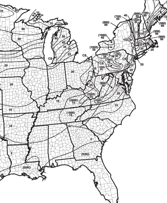
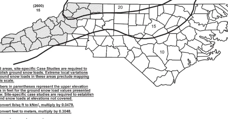
1608.1 General. Design snow loads shall be determined in accordance with Chapter 7 of ASCE 7, but the design roof load shall not be less than that determined by Section 1607.
1608.2 Ground snow loads.The ground snow loads to be used in determining the design snow loads for roofs shall be deter-mined in accordance with ASCE 7 or Figure 1608.2 for North Carolina. Site-specific case studies shall be made in areas des-ignated “CS” in Figure 1608.2. Ground snow loads for sites at elevations above the limits indicated in Figure 1608.2 and for all sites within the CS areas shall beapproved. Ground snow load determination for such sites shall be based on an extreme value statistical analysis of data available in the vicinity of the site using a value with a 2-percent annual probability of being exceeded (50-year mean recurrence interval).
SECTION 1609 WIND LOADS
1609.1 Applications.Buildings, structures and parts thereof shall be designed to withstand the minimum wind loads pre-scribed herein. Decreases in wind loads shall not be made for the effect of shielding by other structures.
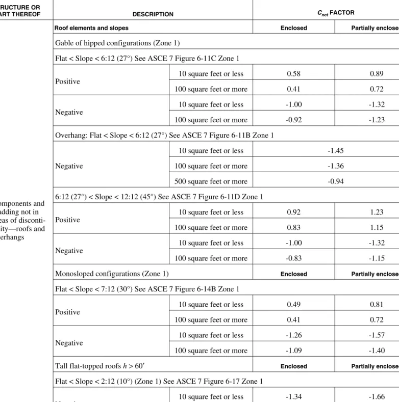
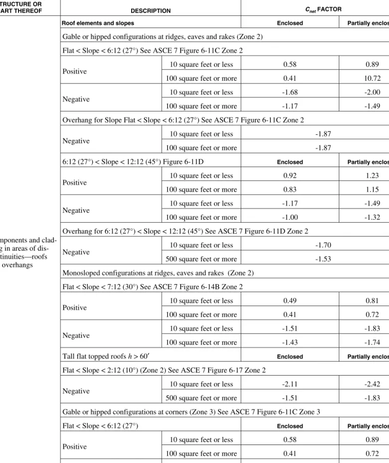
1609.1.1 Determination of wind loads. Wind loads on every building or structure shall be determined in accor-dance with Chapter 6 of ASCE 7 or provisions of the alter-nate all-heights method in Section 1609.6. The type of opening protection required, the basic wind speed and the exposure category for a site is permitted to be determined in accordance with Section 1609 or ASCE 7. Wind shall be assumed to come from any horizontal direction and wind pressures shall be assumed to act normal to the surface con-sidered.
Exceptions:
1. Subject to the limitations of Section 1609.1.1.1, the provisions of ICC 600 shall be permitted for applicable Group R-2 and R-3 buildings.
2. Subject to the limitations of Section 1609.1.1.1, residential structures using the provisions of the AF&PA WFCM.
3. Subject to the limitations of Section 1609.1.1.1, residential structures using the provisions of AISI S230.
4. Designs using NAAMM FP 1001.
5. Designs using TIA-222 for antenna-supporting structures and antennas.
6. Wind tunnel tests in accordance with Section 6.6 of ASCE 7, subject to the limitations in Section 1609.1.1.2.
1609.1.1.1 Applicability.The provisions of ICC 600 are applicable only to buildings located within Exposure B or C as defined in Section 1609.4. The provisions of ICC 600, AF&PA WFCM and AISI S230 shall not apply to buildings sited on the upper half of an isolated hill, ridge or escarpment meeting the following conditions:
1. The hill, ridge or escarpment is 60 feet (18 288 mm) or higher if located in Exposure B or 30 feet (9144 mm) or higher if located in Exposure C; 2. The maximum average slope of the hill exceeds 10
percent; and
3. The hill, ridge or escarpment is unobstructed upwind by other such topographic features for a distance from the high point of 50 times the height of the hill or 1 mile (1.61 km), whichever is greater.
1609.1.1.2 Wind tunnel test limitations. The lower limit on pressures for main wind-force-resisting systems and components and cladding shall be in accordance with Sections 1609.1.1.2.1 and 1609.1.1.2.2.
1 6 0 9 . 1 . 1 . 2 . 1 L o w e r l i m i t s o n m a i n wind-force-resisting system. Base overturning moments determined from wind tunnel testing shall be limited to not less than 80 percent of the design base overturning moments determined in accordance with Section 6.5 of ASCE 7, unless specific testing is performed that demonstrates it is the aerodynamic coefficient of the building, rather than shielding from other structures, that is responsible for the lower val-ues. The 80-percent limit shall be permitted to be adjusted by the ratio of the frame load at critical wind directions as determined from wind tunnel testing without specific adjacent buildings, but including appropriate upwind roughness, to that determined in Section 6.5 of ASCE 7.
1609.1.1.2.2 Lower limits on components and clad-ding.The design pressures for components and clad-ding on walls or roofs shall be selected as the greater of the wind tunnel test results or 80 percent of the pressure obtained for Zone 4 for walls and Zone 1 for roofs as determined in Section 6.5 of ASCE 7, unless specific testing is performed that demonstrates it is the aerodynamic coefficient of the building, rather than shielding from nearby structures, that is respon-sible for the lower values. Alternatively, limited tests at a few wind directions without specific adjacent buildings, but in the presence of an appropriate upwind roughness, shall be permitted to be used to demonstrate that the lower pressures are due to the shape of the building and not to shielding.
FIGURE 1608.2–continued
1609.1.2 Protection of openings. In wind-borne debris regions, glazing in buildings shall be impact resistant or pro-tected with an impact-resistant covering meeting the requirements of anapproved impact-resistant standard or ASTM E 1996 and ASTM E 1886 referenced herein as fol-lows:
1. Glazed openings located within 30 feet (9144 mm) of grade shall meet the requirements of the large missile test of ASTM E 1996.
2. Glazed openings located more than 30 feet (9144 mm) above grade shall meet the provisions of the small missile test of ASTM E 1996.
Exceptions:
1. Wood structural panels with a minimum thickness of7/
16inch (11.1mm) and maximum panel span of 8 feet (2438 mm) shall be permitted for opening protection in buildings with a mean roof height of 45 feet (13 716 mm) or less. Panels shall be precut so that they shall be attached to the framing sur-rounding the opening containing the product with the glazed opening. Panels shall be secured with the attachment hardware provided. Attachments shall be designed to resist the components and cladding loads determined in accordance with the provisions of ASCE 7. Attachment in accordance
with Table 1609.1.2 is permitted for buildings with a mean roof height of 45 feet (13 716 mm) or less where wind speeds do not exceed 140 mph (63 m/s).
2. Glazing in Occupancy Category I buildings as defined in Section 1604.5, including greenhouses that are occupied for growing plants on a produc-tion or research basis, without public access shall be permitted to be unprotected.
3. Glazing inOccupancy CategoryII, III or IV build-ings located over 60 feet (18 288 mm) above the ground and over 30 feet (9144 mm) above aggre-gate surfaced (stone ballast or gravel) roofs located within 1,500 feet (458 m) of the building shall be permitted to be unprotected.
1609.1.2.1 Louvers.Operable louvers protecting intake and exhaust ventilation ducts not assumed to be open that are located within 30 feet (9144 mm) of grade shall meet requirements of anapprovedimpact-resisting standard or the large missile test of ASTM E 1996.
1609.1.2.2 Garage doors.Garage door glazed opening protection for wind-borne debris shall meet the require-ments of an approved impact-resisting standard or ANSI/DASMA 115.
FIGURE 1608.2—continued