SIP CLF: A Common Log Format (CLF) for the Session Initiation Protocol
(SIP)
Vijay K. Gurbani
Bell Laboratories/Alctel-Lucent
Eric Burger
Georgetown University
Carol Davids, Tricha Anjali
Illinois Institute of Technology
Abstract
Web servers such as Apache and web proxies like Squid support event logging using a common log format. The logs produced using these de-facto standard formats are invaluable to system administrators for trouble-shooting a server and tool writers to craft tools that mine the log files and produce reports and trends. The Session Initia-tion Protocol (SIP) does not have a common log format, and as a result, each server supports a distinct log for-mat. This plethora of formats discourages the creation of common tools. Whilst SIP is similar to HTTP, there are a number of fundamental differences between a session-mode protocol and a stateless request-response protocol. We propose a common log file format for SIP servers that can be used uniformly by proxies, registrars, redi-rect servers as well as back-to-back user agents. Such a canonical file can be used to train anomaly detection sys-tems and feed events into a security event management system.
1
Introduction and problem statement
Servers executing on Internet hosts produce log records as part of their normal operations. A log record is, in essence, a summary of an application layer protocol data unit (PDU), that captures in precise terms an event that was processed by the server. These log records serve many purposes, including analysis and troubleshooting.
Web servers such as Apache and Squid support event logging using a Common Log Format (CLF), the com-mon structure for logging requests and responses ser-viced by the web server. One can argue that a good part of the success of Apache has been its CLF because it al-lowed third parties to produce tools that analyzed the log data and generated traffic reports and trends. The Apache CLF has been so successful that it become the de-facto standard in producing logging data for web servers. To-day, one can configure many commercial web servers to
produce logs in this format.
The inspiration for the SIP CLF is the Apache CLF [3] (see also http://httpd.apache.org/docs/2.2/logs.html). However, the state machinery for a HTTP transaction is much simpler than that of the SIP transaction, as we will describe below. The SIP CLF needs to do considerably more than the Apache CLF.
The Session Initiation Protocol [6] is an Internet mul-timedia session signaling protocol. A typical deployment of SIP includes SIP entities from multiple vendors. Cur-rently, if these entities are capable of producing a log file of the transactions being handled by them, the log files are in a proprietary format. The result of the multiplicity of log file formats is the inability of support staff to easily trace a call from one entity to another. Likewise, it makes it difficult to craft common tools that will perform trend analysis, debugging and troubleshooting across the SIP entities of multiple vendors. More importantly, a global view of the call, following a call trace through multiple devices from multiple vendors is very difficult to con-struct.
SIP does not currently have a common log file format. This paper provides the rationale to establish a SIP CLF and identifies the required minimal information that must appear in any SIP CLF record.
The rest of this paper is structured as follows. Sec-tion 2 provides a background on SIP and introduces the domain-specific nomenclature associated with the proto-col. Section 3 motivates the use cases of SIP CLF. Sec-tion 4 documents the complexity of the SIP protocol that makes it harder to log entries atomically when compared to the HTTP protocol. Section 5 outlines the alternative approaches to SIP CLF, and Section 6 presents the SIP CLF data model. Section 7 shows two examples of SIP entities producing SIP CLF records. Section 8 summa-rizes the paper and lists ongoing work we are involved with in SIP CLF.
2
SIP background
A SIP ecosystem consists of user agents, proxy servers, redirect servers, and registrars. Of special interest to us with respect to this paper are user agents and proxy servers.
There are two types of SIP user agents: a user agent client (UAC) and a user agent server (UAS). A UAC and a UAS are software programs that execute on a com-puter, an Internet phone, or a personal digital assistant (PDA). A UAC originates requests (i.e. start a multi-media session) and a UAS accepts and acts upon a re-quest. UASes typically register themselves with a regis-trar, which binds their current IP address to an email-like identifier used to identify the user. This registration in-formation is used by SIP proxy servers to route the re-quest to an appropriate UAS.
Proxy servers are SIP intermediaries that provide criti-cal services such as routing, authentication, and forking1.
A SIP proxy, upon the receipt of an incoming call setup request, will determine how to best route the request to a downstream UAS. The request to establish a session in SIP is called an INVITE. An INVITE request generates one or more responses. Responses to requests indicate success or failure, distinguished by a status code. Re-sponses with status code 1xx (100-199) are termed pro-visional responses and serve to update the progress of the call; the 2xx code is for success and higher number for failures. 2xx-6xx responses are termed as final responses and serve to complete the INVITE request. The INVITE request is forwarded by a proxy (through possibly an-other chain of proxies) until it gets to its destination. The destination sends one or more provisional responses fol-lowed by exactly one final response. The responses tra-verse, in reverse order, over the same proxy chain as the request.
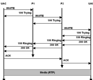
Figure 1 provides a time-line of call establishment between a UAC and a UAS. The request is forwarded through a chain of proxies. With reference to Figure 1, the UAC sends an INVITE to P1 and P1 routes the call further downstream. From the UAC’s reference, P1 is called an outbound proxy. P1 determined that the re-quest should be forwarded to P2 (the UAS is in a differ-ent domain). When the request arrives at P2, it queries its location server and further proxies the request to the UAS. From the UAS point of view, P2 is the inbound proxy. The UAS issues a provisional response followed by a final response. The session is setup when the UAC receives the final response and sends out a new request called an ACK (the ACK and any subsequent requests may flow directly between the endpoints, as dictated by 1Forking is the act of replicating an incoming request to multiple outgoing requests and subsequently collating the responses arriving on each branch.
Figure 1: Session Setup in SIP
the routing policies of the intermediary proxies. Some proxies may elect to stay in the session such that all sub-sequent requests flow through them. In Figure 1, proxy P2 has done so and thus receives the ACK request from the UAC.) A salient note in Figure 1 is that media flows directly between the two endpoints, unhindered by rout-ing through the intermediaries as the signalrout-ing was.
SIP is a text-based, request-response protocol refer-encing the familiarity of other similar protocols such as HTTP and FTP. The base protocol as described in RFC3261 [6] has six methods and six classes of re-sponses (100 to 600.) For instance, a request using the INVITE method to setup a multimedia session is de-picted below. A request (and a response) consists of headers separated by a blank line from the body (or load) of the SIP message. In the example below, the pay-load consists of SDP and describes the capabilities of the sender of the request.
INVITE sip:[email protected] SIP/2.0 To: Robert <sip:[email protected]>
From: Alice <sip:[email protected]>;tag=0ij8z Via: SIP/2.0/UDP a.example.org;branch=z9hG4bKnash CSeq: 89187 INVITE
Call-ID: [email protected] Content-type: application/sdp
v=0
o=alice 2890844526 2890844526 IN IP4 a.example.org
s=-c=IN IP4 192.0.2.101 t=0 0
m=audio 49172 RTP/AVP 0 a=rtpmap:0 PCMU/8000
A corresponding response to the above request would be:
To: Robert <sip:[email protected]>;tag=i8160 From: Alice <sip:[email protected]>;tag=0ij8z Via: SIP/2.0/UDP a.example.org;branch=z9hG4bKnash CSeq: 89187 INVITE
Call-ID: [email protected]
A request elicits one or more provisional response (class 100) and exactly one final response (drawn from 200 - 600 class.) In the example above, the recipient of the INVITE request is indicating that the recipient’s phone is ringing. Note also that a payload is optional in a SIP message; the response above does not contain one. Finally, the notion of a transaction and dialog is used pervasively in SIP. A transaction is the logical grouping of a request, one or more provisional responses and ex-actly one final response. The definition of a transaction is made more complex in SIP because of the manner in which the protocol is defined. An INVITE request that elicits a non-2xx response considers the ACK request to be a part of the same INVITE transaction. On the other hand, an ACK request that acknowledges a 2xx-class re-sponse to the original INVITE is considered to be a trans-action of its own (albeit one without any response.)
A dialog is the logical relation between a UAC and a UAS. Dialogs are created end-to-end, i.e., SIP intermedi-aries may route requests downstream and responses up-stream, but they do not create a dialog, choosing instead to be purely transactional entities. A dialog represents shared state used by the UAC and UAS and is identified by the Call-ID header and the tags from the To and From headers. While transactions have a short timespan — usually to the order of half a minute — dialogs may per-sist for hours or even days between a UAC and a UAS.
3
Motivation and use cases
As SIP becomes pervasive in multiple business domains and ubiquitous in academic and research environments, it is beneficial to establish a CLF for the following reasons:
• Common reference for interpreting events: In a
lab-oratory environment or an enterprise service offer-ing there will typically be SIP entities from multiple vendors participating in routing requests. Absent a CLF format, each entity will produce output records in a native format making it hard to establish com-monality for tools that operate on the log file.
• Writing common tools: A CLF format allows
in-dependent tool providers to craft tools and applica-tions that interpret the CLF data to produce insight-ful trend analysis and detailed traffic reports. The format should be such that it retains the ability to be read by humans and processed using traditional Unix text processing tools.
• Session correlation across diverse processing
ele-ments: In operational SIP networks, a request will typically be processed by more than one SIP server. A SIP CLF will allow the network operator to trace the progression of the request (or a set of requests) as they traverse through the different servers to es-tablish a concise diagnostic trail of a SIP session. Note that tracing a request through a set of servers is considerably easier when all the servers belong to the same administrative domain.
• Message correlation across transactions: A SIP
CLF can enable a quick lookup of all messages that comprise a transaction (e.g., ”Find all messages corresponding to server transaction X, including all forked branches.”)
• Trend analysis: A SIP CLF allows an
administra-tor to collect data and spot patterns or trends in the information (e.g., ”What is the domain where the most sessions are routed to between 9:00 AM and 12:00 PM?”)
• Train anomaly detection systems: A SIP CLF will allow for the training of anomaly detection systems that once trained can monitor the CLF file to trig-ger an alarm on the subsequent deviations from ac-cepted patterns in the data set. Currently, anomaly detection systems monitor the network and parse raw packets that comprise a SIP message – a process that is unsuitable for anomaly detection systems [5]. With all the necessary event data at their disposal, network operations managers and information tech-nology operation managers are in a much better po-sition to correlate, aggregate, and prioritize log data to maintain situational awareness.
• Testing: A SIP CLF allows for automatic testing of
SIP equipment by writing tools that can parse a SIP CLF file to ensure behavior of a device under test.
• Troubleshooting: A SIP CLF can enable cursory
trouble shooting of a SIP entity (e.g., ”How long did it take to generate a final response for the INVITE associated with Call-ID X?”)
• Offline analysis: A SIP CLF allows for offline
anal-ysis of the data gathered. Once a SIP CLF file has been generated, it can be transported to a host with appropriate computing resources to perform subse-quent analysis.
• Real-time monitoring: A SIP CLF allows
admin-istrators to visually notice the events occurring at a SIP entity in real-time providing accurate situa-tional awareness.
4
Challenges in establishing a SIP CLF
Establishing a CLF for SIP is a challenging task. The be-havior of a SIP entity is more complex when compared to the equivalent HTTP entity. Unlike HTTP, where the origin server has all the information required to gener-ate the HTTP CLF when it services a request, in SIP the information becomes available over time at a SIP server. Base protocol services such as parallel or serial fork-ing elicit multiple final responses. Ensufork-ing delays be-tween sending a request and receiving a final response all add complexity when considering what fields should comprise a CLF and in what manner. Furthermore, un-like HTTP, SIP groups multiple discrete transactions into a dialog, and these transactions may arrive at a varying inter-arrival rate at a proxy. For example, the BYE trans-action usually arrives much after the corresponding IN-VITE transaction was received, serviced and expunged from the transaction list. Nonetheless, it is advantageous to relate these transactions such that automata or a human monitoring the log file can construct a set consisting of related transactions.
ACK requests in SIP need careful consideration as well. In SIP, an ACK is a special method that is associ-ated with an INVITE only. It does not require a response, and furthermore, if it is acknowledging a non-2xx re-sponse, then the ACK is considered part of the original INVITE transaction. If it is acknowledging a 2xx-class response, then the ACK is a separate transaction consist-ing of a request only (i.e., there is not a response for an ACK request.) CANCEL is another method that is tied to an INVITE transaction, but unlike ACK, the CANCEL request elicits a final response.
While most requests elicit a response immediately, the INVITE request in SIP can pend at a proxy as it forks branches downstream or at a user agent server while it alerts the user. Rosenberg et al. [6] require the server transaction to send a 1xx-class provisional response if a final response is delayed for more than 200 ms. A SIP CLF log file needs to include such provisional re-sponses because they help train automata associated with anomaly detection systems and provide some positive feedback for a human observer monitoring the log file.
5
Alternative approaches to SIP CLF
The two existing approaches that approximate what SIP CLF does are Call Detail Records (CDRs) and Wireshark packet sniffing.
5.1
SIP CLF and CDRs
CDRs are used in operator networks widely and with the adoption of SIP, standardization bodies such as 3GPP
have subsequently defined SIP-related CDRs as well. To-day, CDRs are used to implement the functionality ap-proximated by SIP CLF, however, there are important differences.
First, SIP CLF operates natively at the transaction layer and maintains enough information in the informa-tion elements being logged that dialog-related data can be subsequently derived from the transaction logs. Thus, esoteric SIP fields and parameters like the To header, in-cluding tags; the From header, inin-cluding tags, the CSeq number, etc. are logged in SIP CLF. By contrast, a CDR is used mostly for charging and thus saves information to facilitate that very aspect. A CDR will most certainly log the public user identification of a party requesting a service (which may not correspond to the From header) and the public user identification of the party called party (which may not correspond to the To header.) Further-more, the sequence numbers maintained by the CDR may not correspond to the SIP CSeq header. Thus it will be hard to piece together the state of a dialog through a sequence of CDR records.
Second, SIP is also being deployed outside of operator- managed VoIP networks. Universities, research laboratories, and small-to-medium size companies are deploying SIP-based VoIP solutions on networks owned and managed by them. Much of the latter constituencies will not have an interest in generating CDRs, but they will like to have a concise representation of the messages being handled by the SIP entities in a common format.
Finally, out of necessity, CDR generation will tie sig-naling to media packets and thus be available only on network servers that can correlate the media and signal-ing packets. By contrast, SIP CLF is not tied to media packets. As such, it can be generated by network servers as well as end user agents. The latter entities in particular increasingly include resource constrained devices (mo-bile phones); thus, a light-weight log generation method like SIP CLF is more amenable to these devices.
5.2
SIP CLF and Wireshark packet
cap-ture
Wireshark (http://www.wireshark.org) is a popular raw packet capture tool. It contains filters that interpret SIP at the protocol level and decompose a captured message into its individual header components. While Wireshark is appropriate to capture and view discrete SIP messages, it does not suffice to serve in the same capacity as SIP CLF for two reasons.
First, all SIP entities that need to save SIP CLF records would require a Wireshark library for different operat-ing systems and configurations to link into. Second, and more importantly, if the SIP messages are exchanged over a TLS-oriented transport, Wireshark will be unable
to decrypt them and render them as individual SIP head-ers.
6
Data model
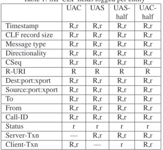
The list below contains definitions of the fields that will provide minimal information that must be present in a SIP CLF record. We present these fields in Table 1, dis-tinguishing between transactions that are initiated at the end points (UAS and UAC) and those that are initiated at intermediary proxies, (UAS-half, UAC-half).
• Timestamp — Date and time of the request or re-sponse represented as the number of seconds and milliseconds since the Unix epoch.
• Size of the SIP CLF record — The total number of
bytes that comprise the SIP CLF record. This allows systems that do post-analysis on the log file to skip the record if it is not of interest.
• Message type — An indicator of whether the SIP
message is a request or a response. The allowable values for this field are R (for Request) and r (for response).
• Directionality - An indicator of whether the SIP
message is received by the SIP entity or sent by the SIP entity. The allowable values for this field are s (for message sent) and r (for message received).
• Source:port:xport — The DNS name or IP address
of the upstream client, including the port number and the transport over which the SIP message was received. The port number must be separated from the DNS name or IP address by a single ’:’. The transport must be separated from the port by a sin-gle ’:’. The allowable values for the transport are governed by the ”transport” production rule in Sec-tion 25.1 of Rosenberg et al. [6]2.
• Destination:port:xport — The DNS name or IP
ad-dress of the downstream server, including the port number. The port number must be separated from the DNS name or IP address by a single ’:’. The transport must be separated from the port by a sin-gle ’:’. The allowable values for the transport are governed by the ”transport” production rule in Sec-tion 25.1 of Rosenberg et al. [6].
• From — The From URI, including the tag. In SIP,
the From URI specifies the sender of a request. The tag is a URI parameter that is used to identify a dia-log between two endpoints.
2The valid values are tcp, udp, tls and sctp. The production rule allows for the set of values to be extended in the future.
• To — The To URI, including the tag. In SIP, the To
URI is the logical recipient of the request. The tag has the same semantics as that of the From URI.
• Callid — The Call-ID header. In SIP, a Call-ID
header groups all transactions exchanged between a UAC and UAS.
• CSeq — The CSeq header, used for sequencing.
• R-URI — The Request-URI, including any URI
parameters. In SIP, the R-URI identifies the ulti-mate recipient of the request. SIP intermediaries use it to route the request towards the destination UAS. The R-URI occurs on the topmost line of a SIP request (it is not present in a SIP response); in the SIP request shown in Section 2, the R-URI is
sip:[email protected].
• Status — The SIP response status code (i.e., 100,
200, etc.) Status lines occur only in responses; in the SIP response shown in Section 2, the status is
180.
SIP Proxies may fork, creating several client transac-tions that correlate to a single server transaction. Re-sponses arriving on these client transactions, or new re-quests (CANCEL, ACK) sent on the client transaction need log file entries that correlate with a server trans-action. The last two data model elements provide this correlation.
• Server-Txn - Server transaction identification code
- the transaction identifier associated with the server transaction. Implementations can reuse the UAS server transaction identifier (the topmost branch-id of the incoming request, with or without the magic cookie), or they could generate a unique identifi-cation string for a server transaction (this identifier needs to be locally unique to the server only.) This identifier is used to correlate ACKs and CANCELs to an INVITE transaction; it is also used to aid in forking as explained later in this section. (See Sec-tion 7 for usage.)
• ClientTxn Client transaction identification code
-this field is used to associate client transactions with a server transaction for forking proxies or B2BUAs. Upon forking, implementations can reuse the value they inserted into the topmost Via header’s branch parameter, or they can generate a unique identifica-tion string for the client transacidentifica-tion. (See Secidentifica-tion 7 for usage.)
Building extensibility in the SIP CLF log model is essential because invariably, implementers will want to save other SIP headers not covered by the mandatory
Table 1: SIP CLF fields logged per entity
UAC UAS UAS-
UAC-half half Timestamp R,r R,r R,r R,r CLF record size R,r R,r R,r R,r Message type R,r R,r R,r R,r Directionality R,r R,r R,r R,r CSeq R,r R,r R,r R,r R-URI R R R R Dest:port:xport R,r R,r R,r R,r Source:port:xport R,r R,r R,r R,r To R,r R,r R,r R,r From R,r R,r R,r R,r Call-ID R,r R,r R,r R,r Status r r r r Server-Txn — R,r R,r R,r Client-Txn R,r — r R,r
ones listed above. In order to do so, the SIP CLF log for-mat supports one or more type-length-value (TLV) fields that appear at the end of the SIP CLF record. As an ex-ample, the SIP CLF record shown in Figure 3 logs the ”Subject” header as an optional TLV field that occurs at the end on line 3.
Each SIP CLF record will contain the data elements in the order shown in the template below:
Record-size Timestamp Message-type Directionality CSeq R-URI
Destination:port:xport
Source:port:xport To From Call-ID
Status Server-Txn Client-Txn [TLV [TLV]...]
Table 1 summarizes how the data elements are logged by a UAC, UAS, UAC-half and UAS-half of a SIP proxy. In Table 1, R implies that the field is logged when a re-quest is handled by that SIP entity, r implies the field is logged when a response is handled by that SIP entity and — implies that the field is not applicable to that SIP entity.
Each SIP entity that generates a SIP CLF log file stores it on local disk, appropriately protected through directory permissions. A log file by its nature reveals both the state of the entity producing it and the nature of the informa-tion being logged. Techniques such as anonymizainforma-tion of user’s private data (URIs, IP addresses, etc.) and ac-cess control to the log file seems reasonable to protect the user’s privacy.
There isn’t any public literature that benchmarks a production-grade commercial SIP proxy with real-world traffic arrival patterns, thus it is difficult to authoritatively derive a message rate and from that, calculate the disk-space requirements associated with a SIP CLF file. Early
academic work on SIP performance [1] and more recent work on SIP overload [2, 4, 7] appear to indicate that steady state is obtained around 200-300 sessions set up per second. Based on this, we make some simplifying assumptions to calculate the disk-space requirements.
One, we assume that SIP proxies fork to at most two end-points (as shown in Figure 2) and there are no mid-dialog messages. Once set up, the session is terminated by a BYE request, which the proxy will have to forward (the BYE request is not shown in Figure 2, but adds 4 messages to the call flow.) In steady state, the server will generate a maximum of 6,000 SIP CLF records (300 sessions per second × 20 messages per session.) The second assumption we make is that the SIP CLF record contains at most 840 bytes (14 mandatory fields at an average of 60 bytes per field.) Thus, in steady state, the server will generate approximately 5 MBytes per second or 435 GBytes per day.
7
Examples
We now present two examples to demonstrate the SIP CLF record format. The first example is simple and only involves Alice registering with her SIP registrar. Alice sends a REGISTER request and the registrar responds with a 200 OK response. The SIP CLF record is gen-erated from the viewpoint of Alice’s UAC; lines 1 and 2 in Figure 3 show how the UAC would log the request and response, respectively (note that in the figure, the line numbers are not part of the SIP CLF record, but are provided to aid subsequent discussion.)
The data model elements on lines 1 and 2 in Figure 3 correspond to the data element template of Section 6.
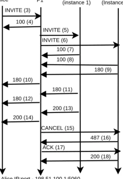
The next example is more complex since it involves a forking proxy. Figure 2 shows the time-line diagram of the call. The numbers in parenthesis besides the requests and responses correspond to the line numbers in Figure 3. In this example, Alice sends out an invitation to Bob. Bob’s proxy (P1) knows that Bob is registered on two endpoints, so it forks the call to both registered instances. After a few provisional responses are received by P1 and proxied back to Alice, Bob’s instance 1 decides to accept the invitation by sending a 200 (line 13). Following the machinations of the SIP protocol, P1 immediately sends the 200 OK to Alice and prepares to cancel the remaining call leg by sending a CANCEL request (line 15) towards Bob’s instance 2. This CANCEL elicits a 200 (line 18), and the pending invitation elicits a 487 (line 16). The 487 is acknowledged by P1 (line 17). The SIP CLF log file created by the exchange of Figure 2 is captured in lines 3 to 18 in Figure 3.
There are some salient points in the SIP CLF log cor-responding to Figure 2. In line 3 of Figure 3, P1 has created a server transaction identification code based on
INVITE (3) 100 (4)
INVITE (5)
Alice P1 Bob(instance 1) Bob(Instance 2)
INVITE (6) 100 (7) 100 (8) 180 (9) 180 (10) 180 (11) 180 (12) 200 (13) 200 (14) CANCEL (15) 487 (16) ACK (17) 200 (18) Alice IP:port - 198.51.100.1:5060 P1 IP:port - 203.0.113.200:5060 Bob’s instance 1 IP:port - 203.0.113.1:5060 Bob’s instance 2 IP:port - [2001:db8::9]:5060
Figure 2: Forking call flow in SIP
the request it received from Alice and has populated the SIP CLF field Server-Txn with it. P1 has not yet cre-ated a client transaction identification code, thus the field
Client-Txn contains a - (horizontal dash.)
In lines 5 and 6, P1 creates two client transactions cor-responding to the two forked branches. Upon the cre-ation of these transactions, a client transaction identifica-tion code is inserted into the SIP CLF log file.
The SIP CLF log file in Figure 3 makes it easy to search for a specific transaction or a state of the session. On a Linux system, a command of"grep c-1-tr"on the logs in the archive will readily yield the information that an INVITE was sent to sip:[email protected], it elicited a 100 followed by a 180 and then a 200.
A command of "grep c-2-tr" yields a more
complex scenario of sending an INVITE to
sip:[email protected], receiving 100 and 180.
However, the log makes it apparent that the request to sip:[email protected] was subsequently
CAN-CEL’ed before a final response was generated, and
that the pending INVITE returned a 487. The ACK to the final non-2xx response and a 200 to the CANCEL request complete the exchange on that branch.
8
Conclusions and future work
We have presented a canonical SIP CLF that is uniquely suited to how SIP operates at the protocol level. The
SIP CLF represents the minimum fields that lend them-selves to trend analysis and serve as information that al-lows system administrators to post-process the records to trace requests, create call trees, or correlate transactions and dialogs.
We have been instrumental in the formation of work-ing group related to SIP CLF in the Internet Engineer-ing Task Force (IETF). This workEngineer-ing group, called SIP-CLF, will standardize the SIP CLF log format. We con-tinue to work in the SIPCLF working group to standard-ize a canonical format that can be used by all vendors. We are also in the process of implementing SIP CLF in two of the most widely used open source SIP stacks: Asterisk (http://www.asterisk.org) and the Kamailio SIP Server (http://www.kamailio.org/w). Both of these SIP servers are used by universities and private and public enterprises; a common SIP CLF will allow all the bene-fits of the SIP CLF format to the system administrators of these SIP servers.
Acknowledgments
We thank the members of the IETF SIPCLF working group, where this work is being standardized for release
as a Request for Comment (RFC) document. Aalok
Singhvi, Gnaneshwar Gatla, Srilakshmi Sheelavati Ka-malanath and Shyam Gajjar at Illinois Institute of Tech-nology (IIT) are implementing SIP CLF in open source SIP servers at the IIT VoIP lab
References
[1] GURBANI, V. K., JAGADEESAN, L.,ANDMENDIRATTA, V. B. Characterizing session initiation protocol (SIP) network perfor-mance and reliability. In ISAS (2005), pp. 196–211.
[2] HILT, V.,ANDWIDJAJA, I. Controlling overload in networks of sip servers. In IEEE International Conference on Network
Proto-cols (October 2008).
[3] LAURIE, B.,ANDLAURIE, P. Apache: The Definitive Guide, third ed. 2002.
[4] NOEL, E.,ANDJOHNSON, C. Initial simulation results that an-alyze sip based voip networks under overload. In International
Teletraffic Congress (June 2007).
[5] RIECK, K., WAHL, S., LASKOV, P., DOMSCHITZ, P., AND
M ¨ULLER, K.-R. A self-learning system for detection of anoma-lous sip messages. Principles, Systems and Applications of IP
Telecommunications. Services and Security for Next Generation Networks: Second International Conference, IPTComm 2008, Heidelberg, Germany, July 1-2, 2008. Revised Selected Papers
(2008), 90–106.
[6] ROSENBERG, J., SCHULZRINNE, H., CAMARILLO, G., JOHN
-STON, A., PETERSON, J., SPARKS, R., HANDLEY, M., AND
SCHOOLER, E. SIP: Session Initiation Protocol. RFC 3261 (Pro-posed Standard), June 2002.
[7] SHEN, C., SCHULZRINNE, H.,ANDNAHUM, E. Session initia-tion protocol (SIP) server overload control: Design and evaluainitia-tion. Springer-Verlag, pp. 149–173.
1: 172 1275930743.699 R s REGISTER-1 sip:example.com 198.51.100.10:5060:udp 198.51.100.1:5060:udp sip:example.com sip:[email protected];tag=76yhh [email protected] - - c-tr-1
2: 173 1275930744.100 r r REGISTER-1 - 198.51.100.1:5060:udp 198.51.100.10:5060:udp
sip:example.com;tag=reg-1xtr sip:[email protected];tag=76yhh [email protected] 200 - c-tr-1
3: 175 1275930743.699 R r INVITE-43 sip:[email protected] 203.0.113.200:5060:udp
198.51.100.1:5060:udp sip:[email protected] sip:[email protected];tag=a11 [email protected] s1tr -Subject,13,"Call me ASAP!"
4: 159 1275930744.001 r s INVITE-43 - 198.51.100.1:5060:udp 203.0.113.200:5060:udp sip:[email protected]
sip:[email protected];tag=a11 [email protected] 100 s1tr
-5: 184 1275930744.998 R s INVITE-43 sip:[email protected] 203.0.113.1:5060:udp 203.0.113.200:5060:udp
sip:[email protected] sip:[email protected];tag=a1-1 [email protected] - s-1-tr c-1-tr
6: 186 1275930745.500 R s INVITE-43 sip:[email protected] [2001:db8::9]:5060:udp 203.0.113.200:5060:udp
sip:[email protected] sip:[email protected];tag=a1-1 [email protected] - s-1-tr c-2-tr
7: 172 1275930745.800 r r INVITE-43 - 203.0.113.200:5060:udp 203.0.113.1:5060:udp sip:[email protected];tag=b1-1
sip:[email protected];tag=a1-1 [email protected] 100 s-1-tr c-1-tr
8: 174 1275930746.100 r r INVITE-43 - 203.0.113.200:5060:udp [2001:db8::9]:5060:udp sip:[email protected];tag=b2-2
sip:[email protected];tag=a1-1 [email protected] 100 s-1-tr c-2-tr
9: 174 1275930746.700 r r INVITE-43 - 203.0.113.200:5060:udp [2001:db8::9]:5060:udp sip:[email protected];tag=b2-2
sip:[email protected];tag=a1-1 [email protected] 180 s-1-tr c-2-tr
10: 170 1275930746.990 r s INVITE-43 - 198.51.100.1:5060:udp 203.0.113.200:5060:udp sip:[email protected];b2-2
sip:[email protected];tag=a1-1 [email protected] 180 s-1-tr c-2-tr
11: 170 1275930747.100 r r INVITE-43 203.0.113.200:5060:udp 203.0.113.1:5060:udp sip:[email protected];tag=b1-1 sip:[email protected];tag=a1-1 [email protected] 180 s-1-tr c-1-tr
12: 173 1275930747.300 r s INVITE-43 - 198.51.100.1:5060:udp 203.0.113.200:5060:udp sip:[email protected];tag=b1-1 sip:[email protected];tag=a1-1 [email protected] 180 s-1-tr c-1-tr
13: 172 1275930747.800 r r INVITE-43 - 203.0.113.200:5060:udp 203.0.113.1:5060:udp sip:[email protected];tag=b1-1 sip:[email protected];tag=a1-1 [email protected] 200 s-1-tr c-1-tr
14: 173 1275930748.000 r s INVITE-43 - 198.51.100.1:5060:udp 203.0.113.200:5060:udp sip:[email protected];tag=b1-1 sip:[email protected];tag=a1-1 [email protected] 200 s-1-tr c-1-tr
15: 191 1275930748.201 R s CANCEL-43 sip:[email protected] [2001:db8::9]:5060:udp 203.0.113.200:5060:udp sip:[email protected];b2-2 sip:[email protected];tag=a1-1 [email protected] - s-1-tr c-2-tr
16: 170 1275930748.991 r r INVITE-43 - 203.0.113.200:5060:udp [2001:db8::9]:5060:udp sip:[email protected];b2-2 sip:[email protected];tag=a1-1 [email protected] 487 s-1-tr c-2-tr
17: 188 1275930749.455 R s ACK-43 sip:[email protected] [2001:db8::9]:5060:udp 203.0.113.200:5060:udp sip:[email protected];b2-2 sip:[email protected];tag=a1-1 [email protected] - s-1-tr c-2-tr
18: 170 1275930750.001 r r CANCEL-43 - 203.0.113.200:5060:udp [2001:db8::9]:5060:udp sip:[email protected];b2-2 sip:[email protected];tag=a1-1 [email protected] 200 s-1-tr c-2-tr
Figure 3: SIP CLF record examples