UNIVERSITY OF TARTU
Institute of Computer Science
Software Engineering Curriculum
Jakob Mass
An Adaptive Mediation Framework for
Workow Management in the Internet of
Things
Master's Thesis (30 ECTS)
Supervisor: Chii Chang, PhD
Supervisor: Satish Narayana Srirama, PhD
Kohanemisel põhinev vahendusraamistik võimaldamaks
töö-voohaldust värkvõrgus
Lühikokkuvõte: Tärkavad värkvõrksüsteemid koosnevad arvukast hulgast he-terogeensetest füüsilistest seadmetest mis ühenduvad Internetiga. Need seadmed suudavad pidevalt ümbritseva keskkonnaga suhelda ja osana lõppkasutaja raken-dusestest edendada valdkondi nagu tark kodu, e-tervis, logistika jne. Selleks, et integreerida füüsilisi seadmeid värkvärgu haldussüssteemidega, on töövoo haldus-süsteemid kerkinud esile sobiva lahendusena. Ent töövoo haldushaldus-süsteemide raken-damine värkvõrku toob kaasa reaalajas teenuste komponeerimise väljakutseid nagu pidev teenusavastus ja -käivitus. Lisaks kehtib küsimus, kuidas piiratud resurs-sidega värkvõrgu seadmeid töövoo haldussüsteemidega integreerida ning kuidas töövooge värkvõrgu seadmetel käitada. Tööülesanded nagu pidev seadmeavastus võivad värkvõrgus osalevatele piiratud arvutusjõudluse ja akukestvusega seadme-tele nagu nutiseadme-telefonid koormavaks osutuda. Siinkohal on võimalikuks lahenduseks töö delegeerimine pilve. Käesolev magistritöö esitleb kontekstipõhist raamistikku tööülesannete vahendamiseks värkvõrgurakendustes. Antud raamistikus modellee-ritakse ning käitatakse tööülesandeid kasutades töövoogusid. Raamistiku proto-tüübiga läbi viidud uurimus näitas, et raamistik on võimeline tuvastama, millal seadmeavastusülesannete pilve delegeerimine on kuluefektiivsem. Vahel aga pole töövoo käitamistarkvara paigaldamine värkvõrgu seadmetele soovitav, arvestades energiasäästlikkust ning käituskiirust. Käesolev töö võrdles kaht tüüpi töövookäi-tust: a) töövoo mudeli käitamine käitusmootoriga ning b) töövoo mudelist tõlgitud programmikoodi käitamine. Lähtudes katsetest päris seadmetega, võrreldi nimeta-tud kahte meetodit pidades silmas süsteemiressursside- ning energiakasutust.
Võtmesõnad: Värkvõrk, Töövoohaldussüsteemid, teenuskompositsioon, Teenusavas-tus, SOA, Teenusorienteeritud arhitektuur, Mobiili- ja pilvearvuTeenusavas-tus, Edge network, Töövookäitus
CERCS: Arvutiteadus, arvutusmeetodid, süsteemid, juhtimine (automaatjuhti-misteooria) (P170)
An Adaptive Mediation Framework for Workow
Manage-ment in the Internet of Things
Abstract: Emerging Internet of Things (IoT) systems consist of great num-bers of heterogeneous physical entities that are interconnected via the Internet. These devices can continuously interact with the surrounding environment and be used for user applications that benet human life in domains such as assisted living, e-health, transportation etc. In order to integrate the frontend physical things with IoT management systems, Workow Management Systems (WfMS) have gained attention as a viable option. However, applying WfMS in IoT faces real-time service composition challenges such as continuous service discovery and invocation. Another question is how to integrate resource-contained IoT devices with the WfMS and execute workows on the IoT devices. Tasks such as continu-ous device discovery can be taxing for IoT-involved devices with limited processing power and battery life such as smartphones. In order to overcome this, some tasks can be delegated to a utility Cloud instance. This thesis proposes a context-based framework for task mediation in Internet of Things applications. In the frame-work, tasks are modelled and executed as workows. A case study carried out with a prototype of the framework showed that the proposed framework is able to decide when it is more cost-ecient to delegate discovery tasks to the cloud. However, sometimes embedding a workow engine in an IoT device is not bene-cial considering agility and energy conservation. This thesis compared two types of workow execution: a) execution of workow models using an embedded work-ow engine and b) execution of program code translations based on the workwork-ow models. Based on experiments with real devices, the two methods were compared in terms of system resource and energy usage.
Keywords: Internet of Things, Workow Management Systems, Service Com-position, Service discovery, Service-Oriented Architecture, Mobile Cloud, Edge network, Workow Execution, Workow Translation
Contents
1 Introduction 8 1.1 Preamble . . . 8 1.2 Motivation . . . 8 1.2.1 Example Scenario . . . 9 1.2.2 Challenges . . . 91.3 Research Objectives and Contribution . . . 11
1.4 Thesis Outline . . . 11
1.5 Publications . . . 11
2 Literature Review 13 2.1 Internet of Things . . . 13
2.1.1 Connectivity . . . 13
2.1.2 The Features of an IoT sytem . . . 14
2.2 Service Oriented Architecture . . . 15
2.3 Service-Oriented IoT . . . 16
2.3.1 Virtualisation of Things . . . 16
2.3.2 Middleware Architecture . . . 17
2.3.3 Discovery . . . 18
2.3.4 Service Description for IoT . . . 18
2.4 Mobile Cloud Computing . . . 21
2.4.1 Task Delegation and Code Ooading . . . 21
2.5 Workow Management Systems . . . 22
2.5.1 Workow Languages . . . 22
2.5.2 Business Process Management Life Cycle . . . 23
2.5.3 Orchestration and Choreography . . . 24
2.6 Mobile Workow Management Systems for IoT . . . 24
2.6.1 Modelling IoT for WfMS . . . 24
2.6.2 Implementing and executing workows in IoT systems . . . 25
3 System Overview 26 3.1 Scenario . . . 26
3.2 SCORPII framework design . . . 27
3.2.1 SCORPII - Mobile Host Side (ScoMH) . . . 28
3.2.2 SCORPII - Utility Cloud Side (ScoUC) . . . 29
3.3 Cost-ecient and Context-aware Workow Approach Selection Model 30 3.3.1 Preliminary . . . 30
3.3.2 Time-span of Approach . . . 33
3.3.3 Raw Cost Elements and Context Parameters of Approach . 34 3.3.4 Cost-Performance Index-based Approach Selection . . . 34
3.3.5 Context-aware weight calculation of the cost elements . . . . 35
3.4 SCORPII Prototype . . . 36
4 Adaptive Workow Execution in the Internet of Things 37 4.1 Overview . . . 37
4.2 Workow Translator implementation . . . 39
4.2.1 Code Generation . . . 39
4.2.2 Groovy language example . . . 39
4.2.3 Workow Engine . . . 40
4.2.4 Test Scenario . . . 40
5 Evaluation 43 5.1 Dynamic Conguration Use Case . . . 43
5.2 Dynamic Conguration Evaluation . . . 44
5.2.1 Context-aware Cost Element Weighing . . . 46
5.3 CPI Scores and Approach Selection . . . 49
5.4 Workow Execution Approach Comparison . . . 51
5.4.1 Bootstrapping . . . 51
5.4.2 Process Execution Time . . . 51
5.4.3 System Resource and Power usage . . . 53
5.5 Bootstrapping and Resource Consumption of Deployment . . . 56
5.6 Discussion . . . 56
6 Conclusion 57 6.1 Future Research Direction . . . 57
List of Figures
1 Example environment with smart objects . . . 10
2 The general SOA model . . . 15
3 A general service-oriented IoT system architecture . . . 17
4 Example of sensor data represented using JSON-LD . . . 19
5 Example of Air Temperature sensor and its value represented using SensorML 2.0 . . . 20
6 Simple BPMN 2.0 process model example . . . 23
7 Service discovery scenario. . . 26
8 Architecture of SCORPII middleware framework. . . 28
9 Workow patterns. . . 33
10 System design overview . . . 37
11 BPMN 2.0 Business process model of parallel tasks . . . 41
12 BPMN 2.0 BP model with no parallel tasks . . . 41
13 Default service workow (simplied) . . . 43
14 Bandwidth measurement comparison . . . 44
15 CPU usage comparison . . . 45
16 Time-span comparison . . . 45
17 CPI comparison of the two approaches in the test scenario with Context A . . . 48
18 CPI comparison of the two approaches in the test scenario with Context B . . . 50
19 Tomcat startup CPU usage . . . 52
20 Tomcat startup Memory usage . . . 52
21 Tomcat startup power consumption . . . 52
22 CPU usage during execution (Parallel BP) . . . 54
23 Memory usage during execution (Parallel BP) . . . 54
24 Power consumption during execution (Parallel BP) . . . 54
25 CPU usage during execution (Non-Parallel BP) . . . 55
26 Memory usage during execution (Non-Parallel BP) . . . 55
List of Tables
1 Context parameters used in the regression training dataset . . . 46
2 Fuzzy representation of the context parameters and weights . . . . 47
3 Weight formulas with regression coecients plugged in . . . 48
4 Final weights of the cost elements with Context A . . . 49
5 Final weights of the cost elements with Context B . . . 50
6 Parallel BP execution times . . . 51
1 Introduction
1.1 Preamble
New, emerging technologies in the elds of mobile and ubiquitous computing pro-mote the phenomena where heterogeneous physical entities connect with the In-ternet via various embedded services and lightweight wireless communication pro-tocols. This development is called the Internet of Things (IoT). Cisco predicts that by 2020, the number of things connected to the Internet will reach 50 billion [Eva11].
IoT bears the potential of greatly inuencing (and improving) the way we work and live. In our daily lives, IoT may enhance assisted living, domotics, e-health, transportation and so forth. Businesses are also expected to benet greatly, e.g. via enhanced logistics, industrial automation, etc [AIM10].
However, introducing various types of things into the same network brings along challenges such as overcoming the heterogeneous nature of the things in terms of varying communication protocols, operating systems and software stack. Further-more, the framework which integrates information systems with physical things should oer an easy-to-use interface for designing the tasks and processes assigned to the things. The framework should be able to re-congure and optimize how the things function together without the need of performing low-level conguration on each individual thing.
One solution for overcoming this issue of management and composition of things is to use Workow Management Systems (WfMS). A workow is a sequence of tasks, events and decisions. Workow management is the eld of designing, ex-ecuting and observing work sequences and providing methods for improving and managing the work eciently.
WfMS can benet IoT by providing a language to dene arbitrary processes in-volving the things and the functionalities they oer. Secondly, WfMS provide the methodology for monitoring, interpreting and improving how these processes are run. By using workow modelling languages such as Web Services Business Pro-cess Execution Language (WS-BPEL) or BPMN 2.0 [bpm], analysts can focus on workow design, while developers can focus on providing software for integrating the things with WfMS.
1.2 Motivation
WfMS for IoT has applications such as in logistics, where cargo could be monitored by a management system in real-time, triggering events immediately after some-thing happens (e.g. the temperature of the goods exceeds a threshold) [GEPF11]. In the smart building domain, a building's heating, ventilating, and air
condition-ing (HVAC) systems can benet from a WfMS. For instance, a hotel could keep track of electricity and heating usage per room, allowing the system to bill the customer according to the usage instead of charging a xed rate [TSD+12]. The
healthcare domain is another very promising target for WfMS IoT applications. In healthcare scenarios, a person is often equipped with wearable sensor devices such as a heart rate and temperature monitor. The sensor data is collected by a broker device and may be forwarded to a remote system, such as a hospital information system, where a doctor is able to use it to analyse patient status [DTRE11]. 1.2.1 Example Scenario
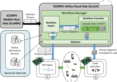
Consider the following scenario: Alice is travelling through urban space inhabited by a large number of smart objects (see Fig. 1). These include smartphones, sensors, media content providers, such as for example text and video content as-sociated with a historic statue near Alice (object A in Fig. 1). Alice is equipped
with a smartphone, which gathers data from nearby things while she is walking. For example, her smartphone may collect noise level, temperature and light levels of various locations in the current area. The smartphone combines these functions of the proximal smart objects with additional services from the web, such as news reports, social media or weather broadcasts. The composition of all this content results in a mobile application for aiding Alice in her travels. However, in some cases, Alice's smartphone does not support the communication standards used by certain smart objects (e.g. deviceC in Fig. 1) . In such cases, Alice's smartphone
uses another type of smart object nearby (object B in Fig. 1), a gateway, which
gathers the data from sensor objects and provides them to Alice's smartphone. This thesis aims to conceive a middleware platform for realizing such scenarios. The proposed Service-oriented Composer for Orchestrating Real-time Proximity-based Industrial Internet of Things (SCORPII), as we call it, manages the work (sensor data gathering, service composition) and objects involved in the scenario by means of using a service-oriented WfMS. As such, it is assumed that the smart objects are capable of executing workows or being invoked as part of workows. 1.2.2 Challenges
Service Discovery In the above scenario however, before the smartphone can retrieve useful data from nearby smart objects, the services (functionality) oered by them must be discovered. The services provided by the smart objects are described in Service description metadata (SDM), which can be obtained in 2 ways:
1. Using direct peer-to-peer communication (such as Bluetooth, WiFi Direct, etc.), to retrieve the SDM directly from the device [Rag15].
A Alice B C Discovery Servers ‘ Web Services Weather Traffic
Figure 1: Example environment with smart objects
2. The smart object provides (e.g. via Radio-frequency identication [RFID]) an address to a cloud discovery server corresponding to the smart object [Goo] (see Fig. 1). This cloud service then provides the SDM. This option is useful when the smart object is a more constrained device in terms of communication capabilities.
Alice's smartphone then processes the SDMs of the nearby devices to lter out the ones which provide the desired services that t the current workow require-ments. However, as the number of nearby devices can be large, processing all these SDMs can be cumbersome for the smartphone. To remedy this, the task of ltering SDMs could be ooaded to the cloud. On the other hand, if the number of devices near Alice is small, processing SDMs locally on smartphone may be preferred to improve responsiveness of the user application.
This raises two questions:
• How does Alice's smartphone decide which processes require computational
task ooading and when?
• How does Alice's smartphone perform the conguration dynamically at
run-time?
Execution approaches A second matter of interest in the previously described IoT scenario is the question of how to execute workows on smart objects? One option is to embed the smart object with a workow engine capable of directly
executing workow models [DTB+15]. The alternative is to translate the
work-ow model into executable code and execute the program code on the smart ob-ject [CK11b, GEPF11, CDD+12]. While both approaches have been previously
explored, a direct comparison of the two is missing to the best of the authors knowledge.
1.3 Research Objectives and Contribution
This thesis aims to reach two goals.
1. To investigate, develop and validate an adaptive middleware framework for proximity based service composition in IoT.
2. Secondly, to develop and validate a testing environment for providing a guideline for developers in the domain of workow execution on resource-constrained devices. More precisely, the guideline focuses on comparing ex-ecuting a workow using as input:
(a) a model of the workow
(b) executable code corresponding to the model.
1.4 Thesis Outline
The rest of this thesis is structured as follows. Section 2 provides a background of technologies and related works. Section 3 details the design and implementation of the SCORPII framework and section 4 describes the workow execution exten-sion for resource-constrained devices. Section 5 compares the performance of the decision-making mechanism in SCORPII and provides a comparison of workow execution approaches. Finally, Section 6 concludes and summarizes the work done in this thesis and provides future research directions.
1.5 Publications
Publications involved in this thesis are listed as follows.
1. C. Chang, S. N. Srirama, J. Mass: A Middleware for Discovering Proximity-based Service-Oriented Industrial Internet of Things, 12th IEEE Interna-tional Conference on Services Computing (SCC 2015), June 27 - July 2, 2015, pp. 130-137. IEEE.
2. C. Chang, S. N. Srirama, J. Mass: Adaptive Mobile Cloud Workow Man-agement System for Service Discovery in Proximity-Based Internet of Things,
International Journal of Services Computing (IJSC), ISSN: 2330-4472, 3(1):44-56, 2015. The Services Society (SS).
3. J. Mass, C.Chang, S. N. Srirama: Workow Model Distribution or Code Dis-tribution? Ideal Approach for Service Composition of the Internet of Things, 13th IEEE International Conference on Services Computing (SCC 2016) (Ac-cepted for publication)
2 Literature Review
This section explains terms, concepts and previous research relevant to this thesis, including the Internet of Things, Service Oriented Architecture, Mobile Cloud Computing and Workow Management Systems.
2.1 Internet of Things
The term Internet of Things (IoT) was coined by Kevin Ashton in 1999 [Ash09], but has since been used to describe various visions, resulting in dierent denitions. The IEEE Internet Initiative has published an entire report [MBR15] aimed at dening IoT. For instance, Vermesan et al. dene:
"The goal of the Internet of Things is to enable things to be con-nected anytime, anyplace, with anything and anyone ideally using any path/network and any service." [VFG+15]
In short, IoT marks the rapid spread of devices with communicating, sensing and actuating capabilities [GBMP13]. Communication is usually achieved using the Internet, but can also involve proximal communication such as Bluetooth. The sensing and actuating abilities of the devices bring together the daily environment of humans and the connected devices. Using sensors, smart objects can capture information from their surroundings, e.g. gather temperature or light readings. With actuator capabilities, smart objects can inuence their surroundings, for example toggle switches, open doors.
2.1.1 Connectivity
As the name suggests, one of the fundamental ideas of IoT is the fact that all things which make up an IoT system are connected to the Internet. This is supported by the Internet Protocol (IP) standard, the latest iteration of which, IPv6, theo-retically allows for2128 unique addresses. This means that using IPv6 virtually all
the objects of our daily lives can be uniquely addressed.
Thanks to advances in wireless technology, the physical size of modern wireless radio modules is minuscule, thus extending even very small objects with wireless capability comes with insignicant overheard in terms of physical size.
In addition to being connected, the IoT objects interact with their surrounding world in various forms. They may collect information from their surroundings (using sensors) or they interact with the physical world by either using actuators or forwarding commands to devices which manipulate the physical world, such as a light.
In the rst IoT conceptualizations, the things were simply represented by Radio-Frequency IDentication (RFID) tags. Between 1999 and 2003 institutions Auto-ID Labs [aut] and EPCGlobal [TAB+15] introduced the concept of attaching
low-cost RFID tags on any products so that they could be tracked. The informa-tion about the products could be retrieved up from databases via the Internet [MBR15]. Later, the IoT vision evolved beyond only RFID-enhanced objects, in-cluding devices with embedded computing capabilities and using other technologies instead of RFID such as Near Field Communication (NFC) or QR-codes (Quick Response Code).
2.1.2 The Features of an IoT sytem
A IEEE Internet Initiative report [MBR15] highlights some distinct features of an IoT system:
• Interconnection of Things: the things are able to communicate with one
another.
• Connection of Things to the Internet: the things are connected to the
Internet, thus an Intranet is not qualied as an IoT network.
• Uniquely Identiable Things: each of the things within the IoT system
are uniquely identiable
• Ubiquity: this feature refers to the "anytime, anyplace" portion of the
denition mentioned previously. Ubiquity represents the idea that the IoT system is available for use whenever necessary for the application scenario, and that IoT scenarios can be found in any application eld (smart home, assisted living, healthcare, logistics, etc.).
• Sensing/Actuation capability: the physical objects are enhanced by
sen-sor / actuator devices, this adds smart behaviour to the objects.
• Embedded Intelligence: the smart objects contain intelligence and
knowl-edge capabilities which allow them to become tools for aiding human life
• Interoperable Communication Capability: the communication of the
Things is based on established standards and protocols.
• Self-congurability: in the heterogeneous environment of IoT, the things
have self-management capabilities such as service discovery and network or-ganization. [CHK+12]
• Programmability: behaviour of the thing can be modied without physical
2.2 Service Oriented Architecture
Service-Oriented Architecture (SOA), also knowns as Service-Oriented Computing (SOC), is a computing paradigm in which the fundamental building blocks for software solutions are software services.
Software services are interfaces that enable devices and their hosted applica-tions to provide their functionalities while being platform-independent and self-contained [Pap03, GP08]. Self-containment here means that the service provider manages its state independently of clients using the software service.
Loose coupling is a feature where each component of a software system utilizes little knowledge about other components in the same system. Loose coupling is fundamental to SOA systems, allowing entities involved in the system to be interacted with using a higher level of abstraction.
Additionally, SOA services support dynamic service discovery and composi-tion. Dynamic service discovery allows clients to query some third-party discovery service to identify which service(s) can meet their requirements.
Service composition allows a system to create a service that utilises the mecha-nisms derived from other providers [GP08]. For example, a location-based service can integrate Google Maps1 and Foursquare2 to provide point-of-interest
informa-tion in a map-review based applicainforma-tion.
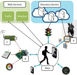
When a service provides its features using application layer Internet standards, such as Hypertext Transfer Protocol (HTTP), XML or REST, it is called a Web service. Web services are well compatible with the fundamental SOA aspects such as platform independence. Service Provider Service Registry Service Requester Publish Bind Find
Figure 2: The general SOA model
The model of SOA consists of three types of participants [IGH+11, Pap03]:
1https://developers.google.com/maps/
1. Service providers, the endpoints of the services. These are the devices which provide the functionality contained in the service.
2. Service requesters, which are the clients who use the functionalities provided by the services.
3. Service registries, who provide information about services providers so that service requesters can discover them.
The interaction between these three has been illustrated in Figure 2. Service Providers notify Service Registries of their existence and their capabilities, after which the Service Registry makes this information (the service descriptor) dis-coverable to others. Using the Service Registry, Service Requesters can discover Service Providers that match their needs and get the necessary metadata to enable service invocation between the Requester and Provider.
2.3 Service-Oriented IoT
SOA has become an important paradigm for realizing IoT middlewares. A mid-dleware is a software layer (or layers) standing between two levels of a software solution. An IoT middleware allows application developers to focus on their do-main (e.g. smart health) without concerning themselves with details about other lower layer technologies such as network protocols.
IoT middleware architectures proposed in the recent years often follow the SOA approach [AIM10, THIG11]. Following the SOA model enables structuring large, complex systems in a way where the individual components are well-dened and can be easily composed and re-composed.
2.3.1 Virtualisation of Things
As an IoT system consists of a large group of heterogeneous objects using dierent communication methods and protocols, it is desirable to have a layer which ab-stracts the dierent technologies so that they can be used with a common language [AIM10]. Using SOA, the heterogeneity and isolation issues of IoT systems can be addressed. By abstracting the IoT devices, things can be utilised as atomic services or they can be used to form a composite service. In practice, Web services have often been used for this [GTW10, DGV09, SJP06].
Web service standards such as SOAP, WSDL etc. reduce the need for gateway devices and translations between the components [GTK+10]. They also allow
orchestration of the services with higher-level Enterprise Resource Planning (ERP) applications. Generally, Web service-based IoT systems are implemented using
Web Service (WS) protocols such as Device Proles for Web Services (DPWS), Constrained Application Protocol (CoAP) or REST.
For connecting the resource-constrained smart objects to the Internet, conven-tional networking standards are not sucient. A key concept, IPv6 over low-power wireless area networks (6LoWPAN), aims to realize IPv6 usage on the low-power smart objects with limited processing capability. 6LoWPAN simplies IPv6 func-tionality, by restricting header formats to very compact sizes. At the same time, the established benets of Internet protocols are preserved, such as re-using exist-ing network infrastructure, existexist-ing standards (such as TCP, UDP, HTTP, CoAP, MQTT), APIs and tools for managing and using IP-networks. [SB11]
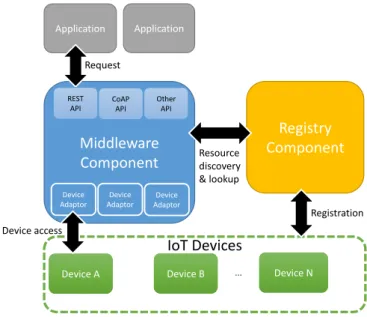
In this way, IoT devices act as the service providers in SOA. 2.3.2 Middleware Architecture
This section describes the common architecture used in existing SOA-based IoT systems, such as MOSDEN [PJZ+14] (part of European Commision project
Ope-nIoT 3 ) and Mobile Digcovery [JLF+14].
Registry Component IoT Devices Middleware Component Application Request Resource discovery & lookup Device access Registration Device A
Device A Device BDevice B ... Device NDevice N Application Device Adaptor Device Adaptor Device Adaptor REST API CoAP API Other API
Figure 3: A general service-oriented IoT system architecture
As presented in Figure 3, end user applications (such as Web or mobile appli-cations) make requests to a middleware component. This request does not need
to specify which protocol or technology is needed to communicate with the IoT devices because the process is handled by the middleware.
The middleware uses a registry component to query for devices which can be used to create a composite service for fullling the requirements of the request.
The Registry component is capable of providing the information of the regis-tered things (e.g. their supported functionalities) to the middleware. After the middleware component has used the Registry component to look up appropriate devices to full the request, the middleware can access the devices to execute the subtasks which compose the original application request. Access to the devices is provided by adaptor components within the middleware. These adaptor com-ponents allow accessing the heterogenous devices which may be using dierent protocols and technologies.
Finally after having accessed the device, the middleware can process the results and respond to the user application with the nal request response.
2.3.3 Discovery
Technologies enabling the discovery of things and their details can be divided into two: a) global network-based and b) edge network-based approaches.
Global network based approaches In this approach, a global registry, ac-cessible anywhere via the Internet, is used to manage a listing of devices and their metadata. There, devices and details regarding their supported features and protocols can be queried. Examples of this are [PJZ+14, JLF+14].
Edge network based approaches In this approach, the smart object being discovered itself serves as the entry-point for obtaining information about the device. The smart object may provide information about itself using technologies such as Bluetooth Low Energy4, Wi-Fi Aware5 or ZigBee6. However, to maintain
energy-eciency for the smart object, the device may provide an address to an external cloud server which provides the details about the smart object. This has been done for example by: Google Physical Web [Goo] or Apple iBeacon [ Ap]. 2.3.4 Service Description for IoT
To be able to advertise smart objects and their capabilities in a formal way, several standards have emerged. These standards enable discovering the heterogenous objects in a structured and machine-readable fashion. By adding semantic data
4https://www.bluetooth.com/
5http://www.wi-fi.org/discover-wi-fi/wi-fi-aware
to the service description of the IoT nodes, the system can support autonomous service invocation.
While metadata description has been well covered in the domain of Semantic Web, the standards therein such as Resource Description Framework (RDF)[G+04]
do not t the constrained resource requirements set by IoT [SRN+15]. Here we
list some standards for IoT device metadata representation.
Sensor Markup Language (SenML) [JAS12] is a data model for connecting sensors and actuators to the Internet by providing device parameters and measure-ments. The format is designed to be able to transport sensor data using devices that are very limited in terms of hardware specication (computing power). SenML can be serialized using JSON, XML and Ecient XML Interchange (EXI) and can be extended with custom attributes.
JSON for Linked Data (JSON-LD) is a format which aims to represent the RDF metadata model in a JSON representation. JSON-LD is endorsed by the World Wide Web Consortium as a promising attempt among the several ap-proaches to capturing RDF semantics using JSON [SRN+15]. Figure 4 shows some
sensor data represented in the JSON-LD format.
{
" @context ": {
"i": " http :// iot .fi/o#",
" accX ": "i: accX ", " accY ": "i: accY ", " accZ ": "i: accZ ",
" magX ": "i: magX ", " magY ": "i: magY ", " magZ ": "i: magZ ",
" temp ": "i: temp ", " timeStamp ": "i: timeStamp "
},
" @id ": "i: accmagSensor01 ",
" @type ": "i: Sensor ",
" accX ": " 618 ", " accY ": " 319 ", " accZ ": " 671 ",
" magX ": " 123 ", " magY ": " 234 ", " temp ": " 22.5 ",
" timeStamp ": " 2012 -05 -18 T12 :00:00 "
}
Figure 4: Example of sensor data represented using JSON-LD [SRN+15]
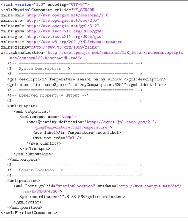
Sensor Model Language (SensorML) [BRGW14] is a standard for modelling and encoding arbitrary sensor-related processes. In SensorML, processes include hardware devices such as sensors and actuators. Processes are dened by their input, output, methods and parameters. As such, SensorML processes are discov-erable and executable.
An example of a temperature sensors reading formatted using SensorML 2.0 is presented in gure 5
<?xml version="1.0" encoding="UTF-8"?> <sml:PhysicalComponent gml:id="MY_SENSOR"
xmlns:sml="http://www.opengis.net/sensorml/2.0" xmlns:swe="http://www.opengis.net/swe/2.0" xmlns:gml="http://www.opengis.net/gml/3.2" xmlns:gmd="http://www.isotc211.org/2005/gmd" xmlns:gco="http://www.isotc211.org/2005/gco" xmlns:xsi="http://www.w3.org/2001/XMLSchema-instance" xmlns:xlink="http://www.w3.org/1999/xlink"
xsi:schemaLocation="http://www.opengis.net/sensorml/2.0 http://schemas.opengis.
net/sensorml/2.0/sensorML.xsd">
<!-- ================================================= -->
<!-- System Description -->
<!-- ================================================= -->
<gml:description> Temperature sensor on my window </gml:description> <gml:identifier codeSpace="uid">myCompany.com.63547</gml:identifier>
<!-- ================================================= -->
<!-- Observed Property = Output -->
<!-- ================================================= -->
<sml:outputs> <sml:OutputList>
<sml:output name="temp">
<swe:Quantity definition="http://sweet.jpl.nasa.gov/2.2/ quanTemperature.owl#Temperature">
<swe:label>Air Temperature</swe:label> <swe:uom code="Cel"/>
</swe:Quantity> </sml:output> </sml:OutputList> </sml:outputs> <!-- ================================================= --> <!-- Sensor Location --> <!-- ================================================= --> <sml:position>
<gml:Point gml:id="stationLocation" srsName="http://www.opengis.net/def/ crs/EPSG/0/4326">
<gml:coordinates>47.8 88.56</gml:coordinates> </gml:Point>
</sml:position> </sml:PhysicalComponent>
Figure 5: Example of Air Temperature sensor and its value represented using SensorML 2.0
[Bot]
speci-cations for enabling secure messaging, discovery, description and eventing that is suitable for automation systems.
2.4 Mobile Cloud Computing
As described by [BYV+09], Cloud Computing (CC) is a paradigm in which
"com-puting is being transformed to a model consisting of services that are commoditized and delivered in a manner similar to traditional utilities such as water, electricity, gas, and telephony."
In cloud computing, users have at their disposal the exact amount of computing power they need and exactly as long as they need it, available for use anywhere. In other words, CC provides users with infrastructure (such as servers, networks and storage), software (middleware services and platforms) in an on-demand fashion, i.e. the resources can be used elastically [DLNW13].
The major providers of Cloud computing applications and platforms today are Amazon, Google, Salesforce, Microsoft. They provide various congurations that are suitable for integration with dierent devices, including mobile phones (smartphones).
The signicant emergence of smartphones within the last decade together with the maturing of Cloud Computing has motivated Mobile Cloud Comput-ing (MCC). In short, MCC is an infrastructure where data processComput-ing (and data storage ) takes place outside of the mobile device.
Via MCC, the mobile environment inherits the features of CC such as elasticity and on-demand usage [DLNW13]. As modern smartphones provide applications and services which aggregate several data sources, involved computational tasks can be quite resource intensive. For example, processing high resolution images or processing natural language on smartphones can be both time- and energy consuming. By utilising MCC, the resource intensive tasks can be ooaded to external computational resources in order to improve the overall performance of the process [FLR13a].
In general, computational ooading in MCC can be performed in two ap-proaches: task delegation and mobile code ooading [FS14].
2.4.1 Task Delegation and Code Ooading
Task delegation represents a computational process, where a process that was orig-inally to be performed on the mobile device, is ooaded to a cloud service which has an equivalent mechanism to execute the process. Task delegation involves mo-bile network communication, which in some cases can cause extra latency. Hence, when a system involves task delegation, the overall cost and performance of the process need to be considered.
On the other hand, according to the ooading model, portions of software may be detected to require too much computational eort and will be accordingly executed either locally or remotely. The remote execution commonly uses an approach similar to traditional Remote Procedure Call (RPC) methods [FLR13b]. When using this model, the questions of what, when, where and how to ooad must be answered. To determine which parts of code could be ooaded, code prolers or manual code annotations are often used [FHT+15]. To determine when
the system should try to save energy by ooading, system prolers can be used [FLR13b].
2.5 Workow Management Systems
Workow Managements Systems (WfMS) are a suiting approach for service com-position [SQV+14, RS04]. A workow is a sequence of tasks, events and decisions.
Some of these elements of the sequence may happen in parallel. Alternatively, a workow may be called a business process (BP) [VDAVH04].
Workow management is the eld of observing and designing workows and providing methods and software tools for managing and improving the work being carried out.
Workow Management Systems are generic software packages for managing business processes [VDAVH04]. WfMS distribute work to to executors (actors) based on a process model [DLRMR13]. Because the system automates the exe-cution and distribution of tasks, it is easy to introduce changes to the workow model, e.g. change the order of tasks done.
However, this process-centric perspective of information systems lacks a gen-eral agreement (standard) on fundamental concepts [vdA13]. As a result, a large number of dierent languages for modelling workows exist. As described by Du-mas et al. [DLRMR13], a workow modelling language generally involves two basic types of nodes: activity nodes and control nodes. Activity nodes represent work that may be executed by a human, software agent or a combination of them. Control nodes represent the ow of execution between activities (the arrangement of work within the sequence). Additionally, event nodes are often also included in a workow modelling language. Event nodes represent events which may happen within the workow or execution environment, to which the workow can then re-act to. For example, upon receiving a message (an event), the user may be asked to respond to it (an activity).
2.5.1 Workow Languages
In this subsection, the major workow modelling languages are summarised. One of the most well known workow languages is Business Process Model and Notation
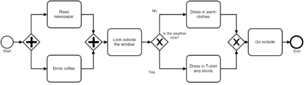
(BPMN 2.0) [bpm], a standard introduced by the Object Management Group (OMG) in 2011. BPMN is a graphical notation. BPMN targets to allow business analysts and system architects to describe processes, resulting in a higher level of abstraction which means that direct execution of BPMN models is not usually existent in BPMN software tools [ODTHVdA06]. Figure 6 presents a simplistic BPMN 2.0 process model, including parallel execution of tasks and a decision point.
Figure 6: Simple BPMN 2.0 process model example
Web Services Business Process Execution Language (WS-BPEL) [AAA+06],
a standard of the Organization introduced by the Organization for the Advance-ment of Structured Information Standards (OASIS), provides a more formal and strict way to describe business processes, integrated with Web service technologies. Because WS-BPEL describes precise semantics for process execution, WS-BPEL based software tools can directly execute WS-BPEL models.
Introduced by the Workow Management Coalition (WfMC), the XML Pro-cess Denition Language (XPDL) [Int01] is a format that aims to be platform-independent, meaning compatibility across dierent modelling and management tools. In essence, XPDL is an exchange format for process denitions between dierent workow languages, it may be considered as the serialization Format for BPMN [xpd].
Comparing these languages, BPMN's main focus is visualization and commu-nication of workows, WS-BPEL focuses on execution with the integration of Web Services and XPDL aims at serialization and documentation [LW13].
2.5.2 Business Process Management Life Cycle
The workow life cycle can be broken down into three distinct phases: (re)design phase, implement/congure phase and the run and adjust phase [vdA13].
In the (re)design phase, the process model is designed. Considering IoT-based WfMS, this involves the question how the smart objects of IoT are represented in the model. The implement/congure phase involves implementing a mapping so that the designed model can be enacted by a workow engine. The run and
adjust phase corresponds to how the WfMS executes the process. In this phase, the process model itself is not redesigned, but conguration adjustments do take place. Executing the process results in log traces which depict how the execution went. This can then be analysed to further improve the process model. As such, the life-cycle begins a new, as the (re)design phase is entered again.
2.5.3 Orchestration and Choreography
WfMS can generally be divided into two architectures: orchestration and chore-ography. The idea of orchestration follows a centralized architecture, where the entire business process is managed by a single management system. Choreography follows a de-centralized architecture, where the process model (or parts of it) are handled by a several external information systems. While orchestration has been the dominant approach in existing IoT-related WfMS, recently, the importance of using choreography for IoT has been recognized. Considering the IoT environment in which participating devices require agile reaction, a centralized, orchestration approach may be insucient [DTRE11]
2.6 Mobile Workow Management Systems for IoT
As mentioned in section 2.3, Service Oriented IoT can abstract the heterogeneous IoT environment into a more uniform set of services. Using WfMS allows for service composition to support any kind of work sequences that are also easy to monitor and manage.
2.6.1 Modelling IoT for WfMS
Bringing IoT objects into WfMS is not a straightforward task, as the objects typi-cally involve dierent communication protocols, network topologies and hardware specications. There are two main approaches to modelling IoT objects for usage in WfMS:
1. Things as services. In this approach, the smart objects are expressed as network services that can be invoked by following the request-response model. The network service embedded in the smart object can be imple-mented e.g. as a SOAP service [PRS+13] or a REST-based service [DTB+15].
Hence, existing modelling standards such as BPMN are left unmodied. 2. Dening new IoT elements. Conventional WfMS assume that all
de-vices involved in the system provide the capability to be directly invoked and automated by the system. However, this assumption may not always be
applicable in IoT systems [MRH15]. IoT objects that have dierent capabil-ities may be connected to the WfMS in dierent ways. Instead of direct IP network connectivity, some things may be connected via multiple network layers or routings. For example, the management system may interact with a gateway service which is connected to multiple sensor nodes.
Another example is continuous tasks, such as sensor data streaming. Existing standard-based BPM modellings tools and WfMS cannot properly handle such processes [MRH15].
As a solution, extensions to languages such as BPMN can be created, which capture the intrinsics of IoT elements and are dierent from the common workow nodes.
2.6.2 Implementing and executing workows in IoT systems
As mentioned previously, the implement/congure phase involves mapping the abstract workow model to a machine-executable software program. Existing com-mon tools for business process execution, such as Activiti7, Camunda8, BonitaBPM9
or Apache ODE10 however lack support for many of the protocols used in IoT
de-vices such as CoAP and MQTT.
IoT objects can take part in a business process not only as a service, but also by executing an entire business process model themselves. To execute a workow on a device, there are two approaches: 1) Execute the process model in a workow en-gine which is running on the thing [DTB+15, GCFP10] and 2) translate the process
model into executable code and run the code on the thing [GEPF11, CDD+12].
7http://activiti.org/
8https://camunda.org/
9http://www.bonitasoft.com/
3 System Overview
This chapter describes the Service-oriented Composer for Orchestrating Real-time Proximity-based Industrial Internet of Things (SCORPII) middleware framework. SCORPII is a service-oriented middleware for real time service composition from heterogeneous proximal pervasive resources. The framework utilizes dynamic elas-tic Cloud computing and workow automation to optimize the task allocation among localhost services and Cloud services based on resource availability and a cost-performance index model.
3.1 Scenario
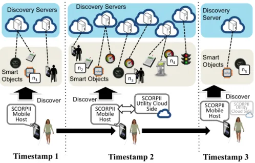
Here we consider the scenario introduced in section 1.2.1, in which Alice is travel-ling in an urban IoT environment with her smartphone. Alice's device is providing a real time content mashup service to Alice to serve her purpose. Since the content mashup process requires continuous proximal discovery of surrounding, it can con-sume a lot of computing power of the mobile device if the number of smart objects is large. As Figure 7 shows, in the rst timestamp, the mobile device (SCORPII Mobile Host) has only discovered a small number of smart objects, which includes 3 smart objects that have registered to two dierent discovery servers, and one smart object (n1) that is available for direct P2P communication.
Figure 7: Service discovery scenario.
While Alice is moving, at timestamp 2, the number of smart objects discovered by Alice's device has greatly increased. The large number of discovery processes
involve the discovery servers from which the mobile device needs to retrieve service description metadata and also process them. Using SCORPII's analysis compo-nent, SCORPII has decided to launch a Utility Cloud service instance to assist certain computational tasks. The tasks which involve interacting and processing the data between SCORPII and external discovery servers have been partitioned as separate workows and have been executed on the Utility Cloud side. Note that in this environment, n1, n2, n3, n4 and n5 are direct communicable smart
objects that do not require further communication with discovery servers. The interaction between Alice's device and those smart objects can be performed in the P2P manner.
Afterwards, at timestamp 3, Alice has moved to an area that consists of a minor number of smart objects. Since the data transmission and processes have decreased, SCORPII's analysis component is able to determine that mobile device-based processing is more cost-ecient. Thus, SCORPII terminates the Utility Cloud side components to reduce the cost. This scenario raises the following questions:
• How does SCORPII decide when and which processes require computational
task ooading?
• How does SCORPII perform the conguration dynamically at runtime?
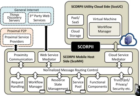
3.2 SCORPII framework design
The framework design is based on the Enterprise Service Bus (ESB) architecture [VdA98]. ESB is a software infrastructure that can easily connect resources by combining and assembling services to achieve a Service Oriented Architecture. Figure 8 illustrates the architecture and the main components of SCORPII. The architecture consists of three parts that are described as follows.
General Internet consists of general Web services such as the discovery servers of the proximal smart objects or third party services that can be utilized to assist certain tasks such as semantic ontology processes. They are reachable through proper Unique Resource Identiers (URIs) and standard communication technolo-gies such as HTTP or CoAP.
Proximal P2P environment consists of various smart objects. SCORPII can utilize common standard protocols to discover and interact with the proximal smart objects to retrieve data or to retrieve the description of their discovery servers that can provide further information or data regarding the smart object.
SCORPII is a dual workow controlled middleware service. It consists of Mobile Host side (ScoMH) and Utility Cloud side (ScoUC). ScoMH is the main controller of the entire middleware and ScoUC is mainly used for resource intensive tasks. The components of each side are described as follows.
Normalized Message Routing Control Request Handling Workflow Manager Resource State Management Service Pool Functional Components Trust/QoS/ Privacy/ Security etc. Proximity Communication Cloud Service Mediator Web Service Mediator
SCORPII Utility Cloud Side (ScoUC)
SCORPII Mobile Host Side (ScoMH) Virtual Machine Workflow Manager SCORPII Things Discovery Servers 3rdParty Web Services General Internet Proximal Service Providers Proximal P2P Cloud Storage PaaS/ SaaS
Figure 8: Architecture of SCORPII middleware framework. 3.2.1 SCORPII - Mobile Host Side (ScoMH)
ScoMH consists of the following main components.
Proximity Communication consists of a number of components that enable short range networked resource discovery and interaction using communication protocols such as, Bluetooth, Wi-Fi direct, ZigBee etc.
Web Service Mediator allows ScoMH to interact with global networked services such as the smart object discovery servers using standard communication protocols such as HTTP or CoAP.
Cloud Service Mediator can dynamically congure and launch virtual machine instances and set up the needed components to enable ScoUC.
Normalized Message Routing Control component handles incoming and out-going messages. It processes the message to meet the required format for the receivers of the message.
Request Handling (RHM H) component receives request messages from other
applications (e.g., a User Application, which provides user interface for users to access SCORPII) and forward the request message to corresponding components via the Normalized Message Routing Control component.
Workow Manager consists of following mechanisms.
Manager components to analyse the status of tasks.
• Manages a collection of pre-dened abstract workow models and approaches.
When it receives a request that contains the goal of the process, a correspond-ing abstract workow model will be executed. A ow relation pattern denes the structure of a set of workow nodes. The denition of abstract workow model and approach will be described in Section 3.3.1.
• Handles runtime workow conguration processes. For example, after a
workow is executed, Task Managers will monitor the cost-eciency of the tasks. If certain tasks are more cost-ecient to be replaced by dierent tasks, the corresponding Task Manager will request the controller of the workow to perform re-conguration.
The Resource State Management component is responsible for continuously monitoring the resource usages such as CPU usage, network bandwidth usage, cloud utility service usage, etc. These resource usages are cost intensive, and are the main elements inuencing the decision making of the adaptation scheme that is described in the next section.
The Service Pool is responsible for managing information on internal services, Utility Cloud services, and services provided by external service providers. It con-tains a collection of the service descriptions of external service providers, the service descriptions of each internal service and each accessible utility Cloud service.
Functional Components are miscellaneous utility components such as semantic metadata matchmaking component, message parsing and calculation component, for calculating the Cost Performance Index (CPI) value described in the next section.
Trust/QoS/Privacy/Security, etc. are additional components needed to pro-vide trustworthy service discovery processes and to improve the quality of service and security requirements. They are not within the scope of this thesis. They are considered as a future research direction.
3.2.2 SCORPII - Utility Cloud Side (ScoUC)
Dierent to the common design which assumes the cloud middleware to be always deployed and always available, SCORPII utility cloud ScoUC is launched on-demand. Same as the other local services, if ScoUC is no longer needed, it will be terminated. One drawback of the on-demand utility cloud component is that it takes time to launch the instance and prepare the cloud platform. For simple processes (e.g., only one single request), ScoUC may not be cost-ecient and will not be needed. The instance can be stored as a snapshot in Cloud storage to reduce
the need of uploading the le directly from mobile host. The main advantage of this design is to fully achieve the pay-per-use concept of Utility Cloud services.
Workow Manager. The Workow Manager (W M) takes care of both workow
execution and also handling requests related to processes. The Workow Manager includes a Workow Engine (W EU C ) which is a workow execution service that
handles the workow passed from the ScoMH.
Secondly, the Workow Manager processes and analyses the request messages in order to perform corresponding actions. For example, a workow that is sent from ScoMH will be passed toW EU C after the payload of the request message has
been analysed.
Paas/SaaS denotes other Web services that have been pre-deployed by SCOR-PII user on Platform as a Service (PaaS)-based Cloud service or the known Soft-ware as a Service (SaaS)-based Cloud service that can be used as the substitution of the self-managed Web application in the virtual machine.
Cloud Storage. SCORPII can also utilize Cloud storage services to store les that are needed for ScoUC. E.g., customized Web application packages.
3.3 Cost-ecient and Context-aware Workow Approach
Selection Model
This section describes the cost-performance index-based scheme for selecting the conguration of workow processes at runtime.
3.3.1 Preliminary
Denition 1 (Cost element setE). E is a nite set. Each e ∈ E is a cost
element dened as a tuple (id, v) where:
id is a unique identication of e.
v is the cost value of e.
A cost element can be CPU usage, RAM, bandwidth, cost of Cloud service and so on.
Denition 2 (Context parameter set X). X is a nite set. Each x∈ X is
a context parameter dened as a tuple (id, v) where:
id is a unique identication of x.
A context parameter can be the remaining battery life, the connection type (3G/WiFi), the mobile data plan cost etc.
Denition 3 (Abstract workow model). An abstract workow model is dened as a tuple (N, F, τ), where:
N is a nite set of nodes.
F ⊆N×N is a set of ow relation rules.
τ : N → Υ maps nodes to node types. A node type can be parallel gateway,
start event, end event, task, sub-process etc.
Letn∈N be a node: •n ={m|(m, n)∈F}is a preset ofn, andn•={m|(n, m)∈
F} is a post-set of n.
An abstract workow model describes the structure of a process in the ab-straction level. Each request received by SCORPII will trigger a corresponding workow execution process, which consists of a set of sequences and parallel tasks. Denition 4 (Task TypetT ype). tT ype is a type of node that represents a
main task which needs to be accomplished in the workow. It is dened as a tuple (ID, IN, OU T) where:
ID is the identication of tT ype.
IN is the input message type.
OU T is the output message type.
AtT ypenode can be substituted by anothertT ypenode or it can be substituted
by another workow as a sub-process as long as the substitution matches the IN
and theOU T of the originaltT ype node dened in the abstract workow model.
Here, we refer to the terms described in [VdA98]: a task that is to be accom-plished is called a work item. A work item is executed by a resource. A resource, in our case, is a localhost component/service or a Web application that has been deployed in the Cloud. When a resource is executing a work item, it is called an activity.
Additionally, we dene the following term:
Denition 5 (Approachh). An approach is dened as a tuple (N, F, τ, α, %, c, $, ρ),
where:
α:N → A maps nodes to activities.
%:A → R maps activities to resources.
c:A → E maps activities to cost elements.
$: ¨E → X maps cost elements to context parameters.
ρ:A → T maps activities to time-span.
Each element of α, %, c, $, ρ is dened as a tuple (key, value).
An approach can consist of one or multiple activities. In other words, an approach can be seen as an individual workow (or a sub-process in BPMN ). A tT ype node in an abstract workow model can be accomplished by dierent
approaches as long as the approach satises the IN and the OU T of the tT ype
node. The approach of a tT ype node can be dynamically changed at runtime of
workow execution. However, the activities in an approach are static unchangeable when the approach is chosen, because the elements (α, %, c, $, ρ) of the approach
have already dened the conguration.
An activity can be performed by a pre-dened approach or it can be performed by a dynamic dened approach at runtime. A dynamic dened approach is based on composing a number of pre-dened approaches to achieve the same output. Example 1 (Dynamic Approach Pattern). Suppose a sequence workow consists of 3 tasks: task1 →task2 →task3. The arrows correspond to the process
ow. task2, which has the IN type as X" and the OU T type as Y". Assume
at runtime, task2 cannot be accomplished by its original dened approach due to
the resources of the activity are suddenly unavailable, and a substitute approach that matches to the IN and theOU T types could not be found in the pre-dened
approach patterns. Hence, the Workow Manager attempts to dene a substitution based on a composite approach. By searching the approach patterns, Workow Manager discovered the following 3 patterns:
Pattern 1 consists of 2 nodes with structure as below: n1 :IN = “X”, OU T = “A1”, n1•={n2}.
n2 :IN = “A1”, OU T = “B1”.
Pattern 2 consists of 6 nodes with structure as below: n1 :IN = “B1”, OU T = “O1”, n1•={n2}.
n3 :IN = “P1”, OU T = “Q1”, n3•={n5}.
n4 :IN = “P2”, OU T = “Q2”, n4•={n5}.
n5 :IN = “Q1”or“Q2”, OU T = “L1”, n5•={n6}.
n6 :IN = “L1”, OU T = “G1”.
Pattern 3 consists of 2 nodes with structure as below: n1 :IN = “G1”, OU T = “F1”, n1•={n2}.
n2 :IN = “F1”, OU T = “Y”.
Figure 9: Workow patterns.
Figure 9 illustrates the conceptual approach patterns described above. By composing the three patterns, an approach with the IN = X" and the OU T =
Y" can be generated for accomplishing thetask2. For more information regarding
to pattern similarity searching scheme can be found in [DDGB09]. 3.3.2 Time-span of Approach
In this thesis, we consider time-span as the performance of an approach. The time-span of an approach is inuenced by the involved tasks and the resources. The formal method to measure the time-span of approaches is omitted in this thesis. The related approach has been introduced in [DB07]. In this prototype, we measured the time-span by manually recording the time-span of each test case using customized methods.
Based on the ow relation rules of a given approach, a number of routes (process ow) can be discovered. Each route may consume dierent time-span depending on the activities involved. Let h be an approach, and Nh denotes the nodes in
approach h. Let Oh be a set of routes that can occur in h. o ∈ Oh denotes one
of the routes. NtT ype
o ⊆ Nh denotes the set of tT ype nodes involved in o route.
To = {ti|1 ≤ i ≤N} corresponding to the time-spans of each activity involved in
NotT ype. E.g., t1 denotes the time-span of the activity that is executed for the task
noden1 ∈ NotT ype, which has been dened in ρ map (see Denition 5). The
T So =
X
i∈|NotT ype|
tsi (1)
where: tsi is time-span value of ni ∈NotT ype.
Based on the calculation above, if the approach h has more than one route, its
time-span value will be presented with [T Shmin,T Shmax] where T Shmin = min
o∈Oh
{T So}
denotes the minimum time-span value and T Shmax = max
o∈Oh
{T So} denotes the
maximum time-span value.
Fundamentally, an approach that has a shorter time-span is considered as hav-ing better performance. However, the shortest time-span may not always mean that the approach is the most ecient selection. Hence, we utilize the cost-performance index (CPI) scheme to optimize the approach selection. The scheme combines fuzzy set [Zad65] and the weight of context [HKZG08]. The reason we use fuzzy set is to compare the performance and cost between approaches instead of using static values.
3.3.3 Raw Cost Elements and Context Parameters of Approach
First, we describe how the raw cost element and raw context parameter sets are generated before we explain the cost-performance index model.
Similar to the measurement of time-span, the cost of an approach is also inu-enced by the number of routes dened in the approach. For each route o ∈Oh of
approach h, letE¨o denote the cost elements ofo dened inE map of approach (see
Denition 5). Each element ¨e ∈ E¨o denotes the sum of the cost elemente's
value from all thetT ype nodes involved ino. The cost elements ofo will be within
[E¨min
o , E¨omax] where E¨omin = min o∈Oh
{¨eo} corresponds to the minimum cost elements,
and E¨max
o = max o∈Oh
{e¨o} corresponds to the maximum cost elements.
3.3.4 Cost-Performance Index-based Approach Selection
Let D be a nite set of time-span values of the selective approachesH, H =
{hl|1 ≤ l ≤ N}, where |D| = |H|, D = {dl|1 ≤ l ≤ |H|}, in which dl is the
maximum time-span of hl by measurement.
Let ST be the shortest time-span in D, where ST = min{dl ∈ D}. The
performance ranking value of an approachhy (denoted byP Rhy) is computed by
P Rhy = 1 + ST P l∈|D| vdl − vdy P l∈|D| vdl (2) where vdl is the value of dl, and vdy is the value of dy.
The formula (2) can generate the ranking value for approaches in which the lower time-span the approach has, the higher ranking value it has.
We need the normalized fuzzy number of the ranking value. Hence, the fuzzy number of an approach's ranking value (denoted by P Pghy) is:
g P Phy = P Rhy P l∈|H| P Rhl (3) where P Rhy is the performance ranking value of hy derived from (2), and gP Phy
is the normalized fuzzy number of the performance ranking value of hy, in which
0≤gP Phy ≤1.
The cost element set (Denition 1) must be comparable between dierent related approaches. If cost elements of approach h1E¨h1 contains the value of
`battery cost', then the approach h2E¨h2 must also contain such a value.
Accord-ingly, the overall CPI between dierent approaches can be computed. 3.3.5 Context-aware weight calculation of the cost elements
Since we are comparing the cost elements between dierent approaches, the nor-malized value of a cost elementv˜¨ey is computed as below.
˜ ve¨y = v¨ey P η∈|E¨hl| v¨eη × w¨ey |W| (4)
where w¨ey is the importance weight of the cost element, and W denotes all the
weight values of cost elements. It is considered because a cost element is dierent for dierent users. For example, when the device battery-life remains 50%, the user may consider that saving the battery life of his/her mobile device is more important than spending money on using cloud services for computational needs. In this case, the weight of the battery life cost element will be higher than the weight of the bandwidth cost of the cloud service. The weight of the cost element for the approach is dependent on the context parameters. The context of a cost elementhl(denoted bye¨ηhl) is retrieved by using function $(¨ehηl)(see Denition
5) where Ke¨hlη ={k¨e hl η 1 , k ¨ ehlη 2 ,· · ·, k ¨ ehlη
we¨y = Θ ¨ ehly 0 + Θ ¨ ehly 1 k ¨ ehlη 1 + Θ ¨ ehly 2 k ¨ ehlη 2 +· · ·+ Θ¨e hl y n k¨e hl η n , n∈N (5)
WhereΘ¨ehly are the regression coecients for a given cost element¨e
y ∈E¨hy and
¨
ey is inuenced by context parameters Ke¨ hl
η . Θe¨hly is a (n+ 1)-dimensional vector.
The average value of the total cost of an approach (denoted by CEhl) is
com-puted as: CEhl = P η∈|E¨ hl| ˜ v¨eη |E¨hl| (6) By applying the basic CPI model, the cost-performance value of an approach (denoted byCP Vhl) is: CP Vhl = g P Rhl CEhl (7)
3.4 SCORPII Prototype
A prototype of SCORPII has been implemented for real Android-based mobile devices together with certain components hosted on Amazon Web service. The prototype consists of two parts:
ScoMH components (i.e. Workow Manager, Resource State Manager, Func-tional Components, etc.) have been implemented in Google Nexus 5 mobile device that runs on Android OS 5.0. The Workow Manager has been implemented as a localhost service that can process BPEL [MIS+03] documents. The current version
of ScoMH's BPEL engine can support sequential and parallel tasks.
ScoUC, which is managed by ScoMH, is a dynamically launched instance on Amazon EC2 (t2.medium) with a Ubuntu OS. ScoUC components are Web ap-plications operated in Apache Tomcat 7 and the workow engine of ScoUC is managed by Apache ODE, which is hosted using Apache Tomcat.
4 Adaptive Workow Execution in the Internet of
Things
4.1 Overview
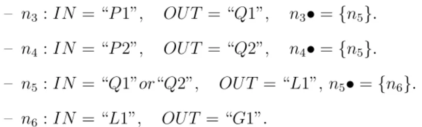
The SCORPII framework design is extended with an additional component, in which the workow manager is extended with the ability to allow IoT devices to execute either a model representation of a business process or a piece of program code corresponding to the workow.
In Fig. 10 we present how this extension is applied to SCORPII. Most impor-tantly, the Workow Manager of SCORPII Utility Cloud side has been extended with a Workow Translator component.
SCORPII Mobile Host
Side (ScoMH) Workflow
Engine Mediator Workflow Translator Wf Engine Business Process Process Segment Process Segment translated to code Process Segment A Code execution B A B Device Information Services
Language plugin container .py .groovy …
General Internet
Workflow Manager SCORPII Utility Cloud Side (ScoUC)
Figure 10: System design overview
The Utility Cloud Side (ScoUC) provides a façade for executing workows in the IoT edge network/environment. The Mobile Host sends their business process to the Cloud Side, where the process model is then parsed. Using a decision making mechanism (as described in section 3.3, ScoUC may execute the process workow entirely in the Cloud, invoking IoT nodes as part of Workow Tasks in the conventional SOA style, alternatively it may partition the workow into segments that are to be executed on the IoT nodes.
Information about an IoT device in the edge network can be inquired using the corresponding Device Information Service (DIS). A DIS provides information regarding the device capabilities such as whether the device has a workow engine or a code execution environment, what kind network protocols are supported, which functions (e.g. sensors, programming languages) are supported.
With this information, a user application which uses the SCORPII Mobile Host Side middleware may congure a composite service involving a number of edge nodes, and submit it to ScoUC for execution.
In our illustrated example, the Cloud Side has determined that the Busi-ness Process provided by the ScoMH should be divided into two segments (sub-processes) to be executed by two IoT devices, A and B.
Device A supports model execution as it is running its own workow engine,
while device B supports code execution only.
For device A, the matching segment of workow is transferred (e.g. in the
BPMN format) to the device. However, for deviceB, ScoUC invokes the Workow
Translator component to convert the workow model document to executable code in a programming language supported byB.
The Workow Translator uses a plugin-based design which allows developers to easily add translators from workow languages to programming languages. The translated business process is sent to the device and executed there.
Communication between the ScoUC and IoT devices is carried out using Inter-net standards such as HTTP (Hypertext Transfer Protocol), CoAP (Constrained Application Protocol) or MQTT (formerly MQ Telemetry Transport). Addition-ally, executing the business process on the IoT device may involve Machine-to-Machine communication with other nearby IoT entities (e.g. via Bluetooth Low Energy, WiFi).
The above description illustrates the conceptual approach of workow execu-tion and service composiexecu-tion at the edge nodes in an IoT environment. Code execution is commonly considered as a lightweight approach that is more feasible to the resource constrained IoT devices [CK11a, GEPF11, CDD+12]. However,
there is no comprehensive comparison between the two approaches in previous research works.
The main question is whether the code execution approach is able to outperform the workow engine approach decidedly or can the work-ow engine approach be applied equally eciently for edge network BP execution?
![Figure 4: Example of sensor data represented using JSON-LD [SRN + 15]](https://thumb-us.123doks.com/thumbv2/123dok_us/11024021.2989651/19.892.132.762.535.798/figure-example-sensor-data-represented-using-json-srn.webp)