UNIVERSITY OF VAASA FACULTY OF TECHNOLOGY
TELECOMMUNICATION ENGINEERING
Satenik Mkrtchyan
LTE-ADVANCED:
TECHNOLOGY
AND
PERFORMANCE
ANALYSIS
Master´s thesis for the degree of Master of Science in Technology submitted for inspection in Vaasa, 21 December, 2011.
Supervisor Prof. (Tech) Mohammed Elmusrati
1 Acknowledgment
It is a pleasure to thank all those who made this thesis possible.
First, I am heartily thankful to my supervisor professor Mohammed Elmusrati whose encouragement, guidance and support from the initial to the final level enabled me to develop an understanding of the subject. He has made available his support in a number of ways through sharing his knowledge and experience with me.
I would like to thank my instructor, Reino Virrankoski for his support and sharing his expertise, and fruitful discussions
I owe my deepest gratitude to Tobias Glocker, who inspired me and made the work progress smooth.
Also I would like to acknowledge Yeranuhi Stepanyan, Ani Arustamyan and Gayane Ajemian for all of their suggestions and corrections concerning the language structure of the document.
Lastly, I offer my regards and blessings to all of those who supported me in any respect during the completion of the project, particularly my dearest family and all my friends for their sincere supplication, feelings and love throughout the whole master study and the work with this thesis.
This thesis would not have been possible unless all these wonderful people have put all their efforts and time together to help me with my thesis.
Thank you very much.
Vaasa, December 5th 2011
2 TABLE OF CONTENTS TABLE OF CONTENTS ... 2 LIST OF ABBREVATIONS ... 5 TABLE OF FIGURES ... 9 LIST OF TABLES ... 10 Abstract ... 11 1. INTRODUCTION ... 11 2. BACKGROUND ... 15
2.1 Long Term Evolution (LTE) Goals... 15
2.2 3GPP Release 8 9 10 ... 16
2.3 LTE-Advanced Requirements ... 16
3. LTE-ADVANCED NETWORK ARCHITECTURE ... 18
3.1. Introduction to SAE and Evolved Packet System ... 18
3.2 LTE-Advanced Network Architecture ... 18
3.2.1 Evolved Packet Core ... 21
3.2.1.1 Mobility management entity ... 21
3.2.1.2 Serving Gateway (S-GW) ... 22
3.2.1.3 Packet Data Network Gateway (P-GW) ... 24
3.2.1.4 Policy and Charging Resource Function (PCRF) ... 24
3.2.1.5 Home Subscription Server (HSS) ... 26
3.2.2 Evolved Universal Terrestrial Radio Access Network (E-UTRAN) ... 27
3.2.3.1 eNodeB ... 27
3.2.3.2 X2 Interface ... 28
3.2.4.User Equipment (UE) ... 29
3.2.5.Services Domain ... 31
3.3EPS Interfaces ... 32
3.3.1 EPS Overview ... 32
3
3.3.3 eNodeB ↔ Serving GW (S1-U) ... 34
3.3.4 MME ↔ MME (S10) ... 35 3.3.5 MME ↔ Serving GW (S11) ... 35 3.3.6 Serving GW ↔ PDN GW (S5/S8) ... 36 3.3.7 SGSN ↔ MME (S3) ... 36 3.3.8 SGSN ↔ Serving GW (S4) ... 37 3.3.9 SGSN ↔ SGSN (S16) ... 37 3.4 Protocol Architecture ... 38
4.LTE RADIO-INTERFACE PHYSICAL LAYER ... 41
4.1 LTE-Advanced Requirements ... 41
4.2 LTE-Advanced Frame Structure ... 43
4.3 DownLink ... 46
4.4 OFDMA (Orthogonal Frequency Division Multiple Access) ... 46
4.5 UpLink ... 49
5.Technology components of LTE-Advanced... 53
5.1 Carrier Aggregation ... 53
5.2Relay Nodes ... 55
5.3 Multiple Input Multiple Output (MIMO) ... 58
5.3 Coordinated Multi-point (CoMP) Technology ... 59
5.4 FemtoCells ... 62
5.5 Autonomous Component Carrier Selection ... 64
5.6 Self-organizing network (SON) ... 66
6.Simulations and Results ... 68
6.1 Description of the transceiver model for downlink and uplink ... 68
6.2 Parameters, Assumptions. ... 72
6.3 BIT ERROR RATE calculations and simulations ... 73
6.3.1 Bit Error Rate (BER) calculations ... 73
6.3.2 Bit Error Rate (BER) simulations and results ... 76
6.4. Power Spectral Density: calculations and simulations. ... 84
6.4.1. Power Spectral Density: calculations... 84
4
6.5 Peak-to-Average Power Ratio: calculations and simulations ... 89
6.5.1 Peak-to-Average Power Ratio calculations ... 89
6.5.2 Peak-to-Average Power Ratio simulations and results ... 90
7.Conclusion and Future Work ... 93
REFERENCES ... 95
5 LIST OF ABBREVATIONS
1G First generation
2G Second generation
3GPP Third Generation Partnership Project
4G 4th generation
AN Access Network
ACCS Autonomous component carrier selection
ANR Automatic Neighbor Relation
AWGN Additive White Gaussian Noise
BER Bit Error Rate
BPSK Binary Phase Shift Keying
CDMA Code division multiple access
CC Component Carrier
CoMP Coordinated Multi-point
CP Cyclic Prefix
CN Core Network
DNS Domain Name Service
DL Downlink
DF Decode and Forward
DFDMA Distributed FDMA
DFT Discrete Fourier Transform
EPS Evolved Packet System
EPC Evolved Packet Core
Eb Bit energy
eNB eNodeB
FD Frequency-Domain
FDD Frequency Division Duplexing
FFT Fast Fourier Transform
FFS Fee-For-Service
GSM Global System for Mobile Communications
GUTI Globally Unique Temporary ID
GP Guard Period
GTP GPRS Tunneling Protocol
GPRS General Packet Radio Service
GERAN GSM/Edge Radio Access Network
HSPA High Speed Packet Access
HSS Home Subscription Server
6
HeMS Home eNodeB Management System
HRPD High Rate Packet Data
HPLMN Home Public Land Mobile Network
IP Internet Protocol
ISD International Subscriber Dialing
ITU International Telecommunication Union
IFFT inverse Fast Fourier Transform
ICIC inter-cell interference coordination
IMS IP Multimedia Subsystem
IMT International Mobile Telecommunications
LFDMA Localized FDMA
LAN Local Area Network
LTE Long-Term Evolution
L1 Layer 1
MIMO Multiple Input Multiple Output
MU-MIMO Multi-User MIMO
MANET Mobile Ad Hoc Network
MATLAB Matrix Laboratory
MAN Metropolitan Area Network
MME Mobility Management Entity
MP Media players
MAC Medium-Access Control
NGMN Next Generation Mobile Networks
NAS Non-Access Stratum
OFDM Orthogonal Frequency Division Multiplexing OFDMA Orthogonal Frequency Division Multiple Access
PDN Packet Data Network
P-GW Packet Data Network Gateway
PCRF Policy and Charging Resource Function
PCC Policy and Charging Control
PCEF Policy and Charging Enforcement Function
RRM Radio Resource Management
PDCP Packet Data Convergence Protocol
PHY Physical Layer
PTS Pilot Timeslots
PAPR Peak-to-Average Power Ratio
PCI Physical Cell ID
7
Pe Error Probability
PSD Power Spectral Density
PCRF Policy and Charging Rules Function
PMIP Proxy Mobile IP
PLMN Private Land Mobile Network
QoS Quality of Service
QAM Quadrature Amplitude Modulation
QPSK Quadrature Phase Shift Keying
QAM Quadrature Amplitude Modulation
QWERTY Standard Computer or Typewriter Keyboard
RF Radio Frequency
RRC Radio Resource Control
RLC radio link control
ROHC Robust Header Compression
RAN Radio Access Network
RAT Remote Administration Tool
RNC Radio Network Controller
SNR Signal-to-Noise Ratio
SC-FDMA Single Carrier Frequency Domain Multiple Access SINR Signal to Interference-and-Noise Ratio
SIMO Single Input, Multiple Output
SGSN Serving GPRS Support Node
SDO Serial Data Out
SAE System Architecture Evolution
S-GW Serving Gateway
SIP Session Initiation Protocol
SON Self organizing networks
SISO Single input single output
SU-MIMO Single-User MIMO
TDD Time Division Duplexing
TTI Transmission time interval
UTRA Universal Terrestrial Radio Access
UTRAN Universal Terrestrial Radio Access Network
UE User Equipment
UL Uplink
VPLMN Visited Public Land Mobile Network
WCDMA Wideband Code Division Multiple Access
8
WCDMA Wideband Code Division Multiple Access
WiMAX Worldwide Interoperability for Microwave Access
9 TABLE OF FIGURES
Figure 1.1 Mobile users subscriptions 13
Figure 3.2.1 LTE Network Architecture 19
Figure 3.2.2 Architecture overview 20
Figure 3.2.1.4 Adding policy control and charging support to the basic EPC chitcture
25
Figure 3.3.1 3GPP architecture domains. 32
Figure 3.3.2.1 Protocol stack for E-UTRAN-Uu and S1-MME 34
Figure 3.4.1 User plane protocol. 38
Figure 3.4.2 Control plane protocol stack. 39
Figure 4.2.1 Frame structure FDD 43
Figure 4.2.2 Frame structure TDD 45
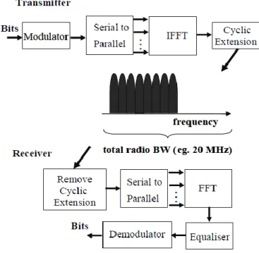
Figure 4.4.1 OFDMA transmitter and receiver 48
Figure: 4.4.2 Cyclic Prefix 48
Figure 4.5.1 SC-FDMA Transmitter 50
Figure: 4.5.2 FDMA 51
Figure 4.5.3 SC-FDMA Receiver 52
Figure 5.1.1 Carrier aggregation types: a) continuous; b) non-continuous. 54
Figure 5.2.1 Relaying scenario: 56
Figure 5.3.1 SU-MIMO and MU-MIMO 58
Figure 5.3.1 Downlink CoMP transmission 61
Figure 5.4.1 Femtocell deployment scenario 62
Figure 5.5.1 Basic principle of autonomous component carrier selection 65
Figure 6.1.a OFDMA Transmitter model 68
Figure 6.1.1 Series to Parallel conversion 69
Figure 6.1.2 Adding unused subcarriers 70
Figure 6.1.2 Adding CP 71
Figure 6.1.b OFDMA Transmitter model 71
Figure 6.3.2.1 Relation between BER and Pe for OFDMA-QPSK 76
Figure 6.3.2.2 Relation between BER and Pe for OFDMA-16QAM 77
Figure 6.3.2.3 Relation between BER and Pe for OFDMA-64QAM 78
Figure 6.3.2.4 Relation between BER and Pe for OFDMA-All modulation types 79
Figure 6.3.2.5 Relation between BER and Pe for SC-FDMA-QPSK 80
Figure 6.3.2.6 Relation between BER and Pe for SC-FDMA-16QAM 81
Figure 6.3.2.7 Relation between BER and Pe for SC-FDMA-64QAM 82
Figure 6.3.2.8 Relation between BER and Pe for SC-FDMA-All modulation ypes 83
Figure 6.4.2.1 Power Spectral Density of OFDMA-QPSK 85
Figure 6.4.2.2 Power Spectral Density of OFDMA-16QAM 86
10
Figure 6.4.2.4 Power Spectral Density of SC-FDMA-QPSK 87
Figure 6.4.2.5 Power Spectral Density of SC-FDMA-16QAM 88
Figure 6.4.2.6 Power Spectral Density of SC-FDMA-64QAM 88
Figure 6.5.2.1 PAPR of OFDMA and SC-FDMA for QPSK 90
Figure 6.5.2.2 PAPR of OFDMA and SC-FDMA for 16QAM 91
Figure 6.5.2.3 PAPR of OFDMA and SC-FDMA for 64QAM 91
LIST OF TABLES
Table 3.2.4.1 LTE-Advanced UE Categories 31
Table 4.2.1 Available Bandwidth is Divided into Physical Resource Blocks 44
Table 4.2.2Uplink-Downlink configurations for LTE TDD 45
Table 6.2.1 Parameters and assumptions used for simulations 72
Table 6.3.2.1 OFDMA-QPSK: BER and Pe results for differen SNR values 76 Table 6.3.2.2 OFDMA-16QAM: BER and Pe results for differen SNR values 77 Table 6.3.2.3 OFDMA-64QAM: BER and Pe results for differen SNR values 78 Table 6.3.2.4 SC-FDMA-64QPSK: BER and Pe results for differen SNR values 80 Table6.3.2.5 SC-FDMA-16QAM: BER and Pe results for differen SNR values 81 Table 6.3.2.6 SC-FDMA-64QAM: BER and Pe results for differen SNR values 82
11 UNIVERSITY OF VAASA
Faculty of technology
Author: Satenik Mkrtchyan
Topic of the Thesis: LTE-Advanced: Technology and Performance Analysis
Supervisor : Prof. Mohammed Elmusrati
Instructor : Reino Virrankoski
Degree : Master of Science in Technology
Department : Department of computer science
Degree Programme : Degree Program in Telecommunication Engineering
Major of Subject: Telecommunication Engineering
Year of Entering the University: 2009
Year of Completing the Thesis: 2011 Pages: 107
Abstract
Wireless data usage is increasing at a phenomenal rate and driving the need for continued innovations in wireless data technologies to provide more capacity and higher quality of service. In October 2009, 3rd Generation Partnership Project (3GPP) submitted LTE-Advanced to the ITU as a proposed candidate IMT-Advanced technology for which specifications could become available in 2011 through Release-10 . The aim of “LTE-Advanced” is to further enhance LTE radio access in terms of system performance and capabilities compared to current cellular systems, including the first release of LTE, with a specific goal to ensure that LTE fulfills and even surpass the requirements of “IMT-Advanced” as defined by the International Telecommunication Union (ITU-R) .
This thesis offers an introduction to the mobile communication standard known as LTE Advanced, depicting the evolution of the standard from its roots and discussing several important technologies that help it evolve to accomplishing the IMT-Advanced requirements. A short history of the LTE standard is offered, along with a discussion of its standards and performance. LTE-Advanced details include analysis on the physical layer by investigating the performance of SC-FDMA and OFDMA of LTE physical layer. The investigation is done by considering different modulation schemes (QPSK, 16QAM and 64QAM) on the basis of PAPR, BER, power spectral density (PSD) and error probability by simulating the model of SC-FDMA & OFDMA. To evaluate the performance in presence of noise, an Additive White Gaussian Noise (AWGN) channel was introduced.
A set of conclusions is derived from our results describing the effect of higher order modulation schemes on BER and error probability for both OFDMA and SC-FDMA. The power spectral densities of both the multiple access techniques (OFDMA and SC-FDMA) are calculated and result shows that the OFDMA has higher power spectral density.
12
1. INTRODUCTION
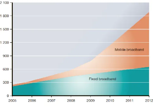
During the past decade the wireless communications industry has increased drastically with over four billion subscribers (Figure 1.1). While the first generation (1G) analog cellular systems had only voice communication with limited roaming, the second generation (2G) digital systems offer better voice quality and higher capacity. Besides, roaming has become more widespread especially in European countries because of limited standards and common spectrum allocations (Beming&Frid 2007).
The two most used second-generation (2G) cellular systems are GSM (global system for mobile communications) and CDMA (code division multiple access). The 2G systems like the 1G analog systems, were first designed to support voice communication and later, released of these standards also supported data transmission, despite the fact that the data rates were lower than those supported by dial-up connections.
Although, in the last decades only a few selected people could use the service, because it was very expensive. Today, the mobile communications are used by a large part of the world population and it has become a part of everyone‟s life. The amount of the subscribers is rising. That‟s why the tasks of evolving mobile technologies are changed from being national or regional concern to wide complex task undertaken by global standards-developing organizations such as the Third Generation Partnership Project (3GPP).
Mobile communication technologies are divided into the following generations:
1G being the analog mobile radio systems of the 1980s
2G the first digital mobile systems
3G the first mobile systems handling broadband data.
Often the Long-Term Evolution (LTE) which is the first release of the LTE (release 8) is called “4G”, but it is in fact the “3.9G” and most specialists also assert that the real developed level of the 4G is LTE release 10, also known as LTE-Advanced. This is because the large amount of labels and the constant competition between them is
13
forcing to increase the new level of the mobile system generations. What is important is the actual system capabilities and how they have evolved.
Figure 1.1: Mobile users subscriptions(Beming&Frid 2007)
LTE and LTE-Advanced are the same technology, with the “Advanced” label primarily being added to show the relation between the LTE release 10 (LTE-Advanced) and ITU/IMT-Advanced. This does not make the LTE-Advanced a different system from the LTE and it is not the final evolution step to be taken for the LTE, in any way.
The 3GPP project developed the first 3G system (WCDMA/HSPA) and now continues to develop the LTE and LTE-Advanced. The first release of the 3G standards couldn‟t reach the promised high-speed data transmissions because in practice the data rates were much lower than it was required by the standards. To make the 3G systems efficient for data transmission, a serious commitment was done by the 3GPP. While HSPA systems were being developed and deployed, the IEEE 802 LMSC (LAN/MAN Standard Committee) introduced the IEEE 802.16e standard for the mobile broadband wireless access. This standard was introduced as an enhancement to the earlier IEEE 802.16
14
standard for the fixed broadband wireless access. OFDMA (orthogonal frequency division multiple access) has been created and introduced as a different access technology which has better data rates and spectral efficiency than provided by the HSPA. Although the IEEE 802.16 family of standards is officially called WirelessMAN in the IEEE, it has been dubbed WiMAX (worldwide interoperability for microwave access) by an industry group named the WiMAX Forum. The mission of the WiMAX Forum is to promote and certify the compatibility and interoperability of broadband wireless access products. The Mobile WiMAX introduced their developed version of the 3G systems which is based on OFDMA technology. The beyond 3G system in the 3GPP is called evolved universal terrestrial radio access (evolved UTRA) and is also widely referred to as a LTE (Long-Term Evolution) (Dahlman&Parkval2011).
The background of the LTE and beyond systems are described in chapter 2. Chapter 3 represents the LTE based systems‟ network architecture including its 4 subsystems, interfaces and protocols. Chapter 4 explains the details of the LTE radio-interface physical layer. Chapter 5 contains the Technology components of LTE-Advanced, such as MIMO, CoMP, relay nodes, femtocell and Self organizing networks (SON). The Simulation model and the Simulation results are provided in chapter 6. Finally this thesis is summarized and future work ideas are given in chapter 7.
15
2. BACKGROUND
LTE-Advanced is a 3GPP standard which describes technological advancements to the Long Term Evolution (LTE). As described in the IMT-Advanced (International Mobile Telecommunications) it should have highly flexible radio interface that aims bridging the gap between the 3rd generation and the 4th generation (4G) standards.
2.1 Long Term Evolution (LTE) Goals
The objective of the LTE is to give a high-data-rate, low-latency and packet-optimized radio access technology supporting flexible bandwidth deployments. At the same time, a new network architecture was made with the goal of supporting packet-switched traffic with seamless mobility, quality of service and little latency. The followings are some of the architectural requirements designed by 3GPP Standards Body for the LTE according to “Traian 2010”
1. An All-IP based system
2. Flat Architecture for Optimized Payload Path 3. Excellent scalability
4. High level of security in Access Network (AN) as well as Core Network (CN) 5. Simple QoS model
6. Low delay times between nodes 7. Efficient radio usage
8. Flexible spectrum utilization 9. Cost efficient deployment
16
Some of the above mentioned targets were achieved by implementing a Flat Architecture with a less number of nodes. The fewer number of nodes helped in reducing latency times and improved overall performance.
2.2 3GPP Release 8 9 10
Although the work on the LTE standard was almost over, the works on the LTE Advanced were kicked off, which is also known as 3GPP Release 10. To make it backward compatible, the LTE-Advanced must share bandwidth with the first release of LTE as well as should be compatible with the equipment of the first release. The 4G should offer a data rate of 1 Gbps with a 100 MHz bandwidth. While OFDM gives an easy way to increase capacity by adding additional subcarriers, the scheduler must include a mix of terminal. While looking at the proposal for the standard, the 3GPP working groups have focused mainly on the physical level. These includes analysis on relay nodes, scalable system bandwidth over 20 MHz, the local optimization of air interface, diversity MIMO, flexible use of spectrum, etc. In the end, the standardization is expected to be included in 3GPP Release 10 timeframe. The importance and timeframe of the LTE Advanced mostly depends on the success of the LTE as the LTE Advanced is built entirely on existing specifications of LTE. After the correction and improvement phase of Release 9, major developments have been introduced to the LTE Release 10. As the LTE- Advanced meets the most standards for ITU 4G, 3GPP work plan is similar to the schedule of ITU. (B. Furht & Ahson / 2009 pp1-2).
2.3 LTE-Advanced Requirements
With the work starting on LTE Advanced, a number of key requirements and key features are coming to light. There are many high level aims for the new LTE Advanced specification. According to (Seidel 2008) the requirement specifications are as follows.
17 Peak data rate DL: 1 Gbps, UL: 500 Mbps
Transmission bandwidth: Wider than approximately 70 MHz in DL and 40 MHz in UL
Latency: C-plane from Idle (with IP address allocated) to Connected in <50 ms and U-plane latency shorter than 5 ms one way in RAN taking into account 30% retransmissions (FFS)
Cell edge user throughput 2 times higher than that in LTE Average user throughput 3 times higher than that in LTE Capacity (spectrum efficiency) 3 times higher than that in LTE Peak spectrum efficiency DL: 30 bps/Hz, UL: 15 bps/Hz
Spectrum flexibility: Support of scalable bandwidth and spectrum aggregation Mobility: Same as that in LTE
Coverage should be optimized or deployment in local areas/micro cell environments with ISD up to 1 km
Backward compatibility and interworking with LTE with the 3GPP legacy systems
18
3. LTE-ADVANCED NETWORK ARCHITECTURE
The LTE network architecture was designed to support the packet-switched traffic with seamless mobility, minimal latency and quality of service (QoS). These means that all services including voice will be provided with packet switched connection. The evolution of the core network is known as SAE - System Architecture Evolution. This new architecture has been designed to provide a remarkably higher level of performance, in accordance with the requirements of the LTE.
3.1. Introduction to SAE and Evolved Packet System
The System Architecture Evolution (SAE), normally referred to as EPC, is the name of the Third Generation Partnership Project (3GPP) standardization work item, which is responsible for the evolution of the packet core network. (Jian Chen, Ling-di Ping 2009). This work item is closely related to the LTE work item, which contains the evolution of the radio network. Evolved Packet System (EPS) covers the core network, the radio access and the terminals that make up the whole mobile system. It also gives support for other non-3GPP high-speed RANs, for example, WLAN, WiMAX etc.
3.2 LTE-Advanced Network Architecture
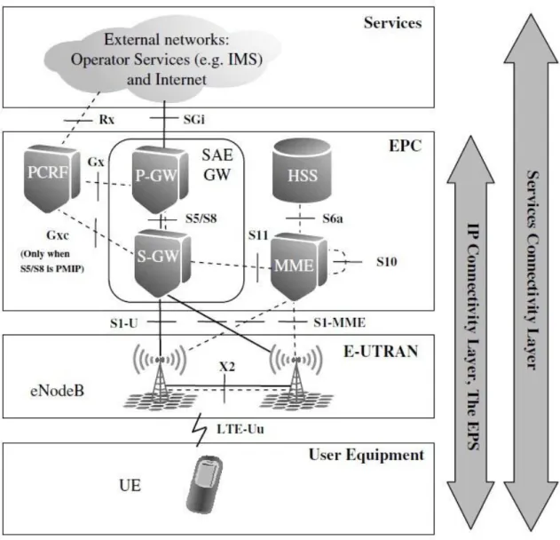
The Figure 3.2.2 describes the LTE Network Architecture with its basic system configuration and logical nodes. These elements are required when E-UTRAN is involved in the Access Network.
The architecture is sub-divided in four main sub-systems: Figure 3.2.1 1. Evolved Packet Core (EPC)
19 3. User Equipment (UE)
4. Services Domain
20 Figure 3.2.2: Architecture overview(Khan 2009)
21
3.2.1 Evolved Packet Core
The LTE Core network architecture was designed with the objective to simplify the overall architecture. The EPC is an essential evolution from GSM / GPRS core network used for the GSM and WCDMA / HSPA. The EPC supports access to the packet-switched domain only, with no access to the circuit switched domain. It consists of several different types of nodes, some of which are the Mobility Management Entity (MME) , Serving Gateway (S-GW) and Packet Data Network Gateway (PDN Gateway, P-GW) (Preben Mogensen, Byung K. Yi /2009).
3.2.1.1 Mobility management entity
The Mobility Management Entity (MME) is the central management entity for the LTE accesses. It is responsible for the connection of the UE by selecting the gateway through which messages are to be exchanged and a level of resources for the UE in cases of attachment and handover. From the perspective of the Core Network, the MME is a main node for controlling the access network of the LTE. During the first attach as well as during handover between the LTE networks, if necessary, it selects the Serving GW for a UE. It is responsible for the activation and de-activation of the bearers on behalf of a UE and also tracking and paging procedures for UEs in idle mode. The MME is responsible for authenticating the end-user, through interaction with the HSS. For UEs, which are in roaming, the MME stops the S6a interface to the UEs home HSS. The MME also ensures that the UE has permission to use an Operator‟s PLMN and also forces any roaming restrictions that the UE may have. In addition, the MME provides control plane functionality for mobility between the LTE and 2G/3G access networks. The S3 interface terminates at the MME from the SGSN (Corici, Vingarzan 2010).
The selection of the MME is done by the MME selection function. Based on the network topology, the Selection process depends on the MME which serves the
22
particular location that a UE is in. If there are several MMEs to serve a particular area, the choice is based on a few different criteria, e.g selecting an MME that reduces the need to change it later or perhaps based on the load balancing needs. MME selection function is located only in the eNB. The architecture supports multiple eNBs connected to multiple Serving GWs as well as MMEs. When an UE tries to connect to E-UTRAN, it provides the eNB with GUTI(Globally Unique Temporary ID) parameters which makes the selection of the suitable MME based on how the GUTI is constructed easier. The GUTI is a worldwide unique identity that shows a specific subscriber context in a specific MME (Harri Holama and Antti Toskala 2009). The information about the load status of the MME‟s is also provided to the eNB within a pool via S1-AP signaling and thus can provide extra information to the eNBs connected to the MME pool. This gives an efficient selection of MME within a pool and also allows triggers towards the UE (using Tracking Area Update or S1 Release procedures) to reconnect to a different MME within a pool when required. From the UE movement point of view, the process of MME selection is also efficient and has been developed to minimize the MME change when serving within certain operating boundaries. When no routing to an MME can be determined from the information provided by the UE, the eNB is responsible for the selection of a desired MME at the UE attachment.
Another responsibility of the MME is Non-Access Stratum (NAS) signaling, which terminates at the MME; the MME also acts as the termination point in the network for the security of NAS signaling, and management of security keys, handling the ciphering protection. Lawful Intercept related to signaling was also handled by the MME (H. Holama & A. Toskala 2009 pp28-29, Agilent bonus material).
3.2.1.2 Serving Gateway (S-GW)
For both the GTP-based and PMIP based network architectures, the Serving GW performs several functions. First, the Serving GW stops the interface towards E-UTRAN; every UE which gets connected to an EPS is aligned with a single Serving GW.
23
The Domain Name Service (DNS) may be used to resolve a DNS string of possible Serving GW addresses which serve the UE‟s location. The Serving GW selection function selects an appropriate Serving GW to serve an UE. The selection of Serving GW is done on the same way as for the MEE. It is affected by a few criteria; on the first place is the fact that its service area may reduce the necessity to change the Serving GW at a later time. Secondly, Serving GW selection may be based on the load balancing needs between different Serving GWs (R. Kreher & K. Gaenger 2011 p12).
Because of the possibility to use either GTP or PMIPv6 over the S5 and S8 interfaces as well as during roaming, there might be multiple PDN connections involving HPLMN and VPLMN, Serving GWs may need to support both protocols for a single UE connected to different PDNs. This may be needed in case a UE has two PDN connections, one with PDN GW in Visited PLMN and one with PDN GW allocated in the Home PLMN. If the PMIPv6 is used on S5 between the Serving GW and the PDN GW in the Visited PLMN, GTP can be used for the other PDN connection with PDN GW in the Home PLMN (M. Olsson & S. Sultana 2009 pp114-116).
As soon as the UE is connected with a Serving GW, it handles the forwarding of end-user data packets as well as performs as a local anchor point when required for inter-eNodeB handover. During handover from LTE to other 3GPP access technologies, for example inter-RAT handover for other 3GPP access technologies, the Serving GW terminates the S4 interface and provides a connection for transferring user traffic from 2G/3G network systems and the PDN GW. The Serving GW sends one or more „endmarkers‟ to the source eNodeB, RNC or SGSN, in order to assist the re-ordering function in the eNodeB, during both the inter-NodeB and inter-RAT handovers,. (H. Holma & etc 2009 p30-31)
The Serving GW will terminate the downlink (DL) path for data, whenever a UE is in idle state. The Serving GW triggers paging towards the UE, in case if new packets arrive. The Serving GW stores and manages information relevant to the UE; for example an internal network routing information or parameters of the IP bearer service.
24
Finally, the Serving GW is responsible for the reproduction of user traffic in case of lawful intercept.
3.2.1.3 Packet Data Network Gateway (P-GW)
The PDN GW, acting as the entry and exit point for the UE data traffic, provides connectivity to external PDNs for the UE. If an UE needs to access more than one PDN, it may be connected to more than one PDN GW. For the UE, the PDN GW allocates an IP address. In both the GTP-based and the PMIP-based versions of the SAE architecture, these PDN GW functions may be applied (R. Kreher & etc.2011 p13). As a gateway, a part of the PDN GW role may be performing packet filtering or deep packet inspection, on a per-user basis. The PDN GW also performs service level gating control and rate enforcement through rate policing and shaping. The PDN GW also marks the uplink and downlink packets with the DiffServ Code Point, as a part of QoS perspective. Finally, a key role of the PDN GW is to act as an anchor for mobility between 3GPP and non-3GPP technologies such as 3GPP2 (CDMA/HRPD) and WiMAX (H. Holma & etc 2009 p55).
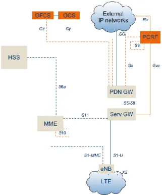
3.2.1.4 Policy and Charging Resource Function (PCRF)
The PCRF (Policy and Charging Rules Function) is one of the most important part of the EPC architecture or in the 3GPP packet core architecture in general, named PCC (Policy and Charging Control) which is responsible for quality-of-service (QoS) handling and charging Figure 3.2.1.4.
25
Figure 3.2.1.4: Adding policy control and charging support to the basic EPC architecture(Khan 2009)
As a policy and charging control element of the SAE architecture, the Policy and Charging Rules Function (PCRF) involves a flow-based charging control as well as policy control decision functionalities. This means that it provides a network-based control related to the flow-based charging, service data flow detection, QoS and gating towards the Policy and Charging Enforcement Function (PCEF) (Holma & etc.2009 pp27-28, R. Nossenson).
For service-aware QoS and charging control, PCC provides operators with latest tools. In wireless networks, where the bandwidth is usually limited by the radio network, it is important to make sure that a utilization of the radio and transport network resources is efficient. Moreover, different services have very different requirements on the QoS, which are required for the packet transport. Since a network generally carries many different services for different users at the same time, it is important to ensure that each service is provided with an appropriate transport path and that the services can co-exist (K.Bogineni, R. Ludwig 2009).
26
When it comes to bandwidth and QoS treatment, PCC makes it possible for a centralized control to ensure that the service sessions are provided with a proper transport. For both the IP Multimedia Subsystem (IMS) as well as non-IMS services, the PCC architecture provides control of the media plane. The PCC also enables the means to control charging on a per-service basis.
The aim of 3GPP was to define an access-agnostic policy control framework, and with this, make it applicable to a number of accesses such as E-UTRAN, GERAN, UTRAN, HRPD and WiMAX.
When a complete roaming model for PCC was introduced, this allows operators to have the same dynamic PCC, also enables the same access to services, independently of the location, whether a user is making this access through a gateway in a visited or their home network (M. Olsson& etc. 2009 pp174-175).
3.2.1.5 Home Subscription Server (HSS)
The HSS, acting as a database, stores the master copy of the subscriber profile, which may contain information about the services that are applicable to the user. This may include information about the allowed PDN connections, and whether it is allowed or not to roaming to the particular visited network. The HSS also stores the Identities of those P-GWs that are in use, for supporting mobility between non-3GPP RANs. The Authentication Center (AuC) is a storage of the permanent key. The key is used to calculate the authentication vectors. The vectors are sent to a visited network for deriving subsequent keys for integrity protection and encryption and user authentication. The AuC is also a part of the HSS (Lescuyer & Lucidarme 2008 pp47-49).
27
3.2.2 Evolved Universal Terrestrial Radio Access Network (E-UTRAN)
The most important function of the EPC is to give IP connectivity to the terminal for both data and voice services. The IP-based packet-switched domain is innately supported by E-UTRAN. The E-UTRAN or Evolved UTRAN is a 3GPP term denoting the RAN that implements the LTE radio interface technology.The development in E-UTRAN is mostly centered on one point, the evolved Node B (eNodeB). All radio functionalities are situated there, i.e. the eNodeB is the termination point for all radio related protocols. The EUTRAN, as a network, is nothing but a mesh of eNodeBs connected to neighboring eNodeBs with the X2 interface. (Furht & etc. 2009 pp6-8)
3.2.3.1 eNodeB
There is at least one eNodeB in the LTE radio network which is the LTE base station. The functionality of the eNodeB has all the features that are needed for realizing the actual wireless connections between the network and user devices.
The eNodeB performs radio resource management and provides the radio interface for Long-Term Evolution (LTE) including radio admission control, radio bearer control, and scheduling of downlink and uplink radio resources for individual UEs. The eNodeB also supports the user plane data‟s IP header compression and encryption. The interconnected between eNodeBs are executed via an interface named X2 (logical); this interface has many uses, e.g. handover. The S1 interface is used of eNodeBs and the EPC connection, which is divided into the control plane and the user plane. The control plane interface called S1- MME, terminates in the MME. Meanwhile, the S1-U interface terminates at the Serving GW and handles user plane traffic. The S1 interface supports pooling, which is a many-to-many relation between the eNodeBs and the MMEs as well as between the eNodeBs and the Serving GW. Another use of the S1 interface is support network sharing. With this, operators may share the radio network,
28
that is the eNodeBs, while maintaining their own EPC networks (H. Holama & etc. 2009 p6, Lescuyer & etc. 2008 pp173-177).
3.2.3.2 X2 Interface
The LTE was created to operate with a one-cell frequency reuse, which means that the same time–frequency resources can be used in surrounding cells. Mainly, the basic control channels are designed to operate properly under relatively low signal-to-interference ratio that may be experienced while using reuse-one frequency deployment.
From a point of view of general system-efficiency, to operate with one-cell reuse and have access to the entire available spectrum in each cell is always beneficial. Though, this may result to relatively large changes in the signal-to-interference ratio, which affects also on the achievable data rates, over the cell area with potentially only relatively low data rates being available at the cell border. Hence, the cell-edge user quality and the system performance, especially, can be further enhanced by allowing for some coordination in the scheduling between cells (Alcatel Lucent white paper 2009).
The main objective of such inter-cell interference coordination (ICIC) is, in case of possibility, avoid simultaneously scheduling transmissions to/from terminals at the cell border in neighboring cells, and in term, avoiding the worst-case interference situations. In order to support such interference coordination, the LTE specification involves several messages that may be used for communicating between eNodeBs using X2 interface (Furht & etc. 2009 p120).
The X2 interface, connecting eNodeBs to each other, is mostly used to support active-mode mobility. It may also be used for multi-cell Radio Resource Management (RRM) functions. The X2 interface is used to support lossless mobility between encircling cells by using packet forwarding. The signaling on X2 interface between eNBs is used for handover preparation. Coordination of scheduling decisions across many cells that exist in different eNodeBs is also supported using signaling over the X2 interface. In LTE
29
scheduling is carried out locally at the eNodeB as there is no higher-level node. This is done by originating messages that carries information about the scheduling strategy between neighboring eNodeBs using the X2 interface. An eNodeB can then use the information provided by a neighboring eNodeB as input to its own scheduling process (Alcatel Lucent white paper 2009).
3.2.4.User Equipment (UE)
„Terminal‟, „End-User Terminal‟, and „User Equipment (UE)‟ terms stand for the demonstration of actual device communicating with the network. Data modems devices of the first generation of LTE, which sometimes are used with the name USB dongles, can be attached to standard laptop computers. Very often people mix up „mobile device‟ with a mobile phone. Today, this is the most requested target-user device and they are in use as portable form factors since the 1980s. Mobile phones have been made for voice services. Later service capabilities have been added, primarily SMS support, e-mail and web surfing, which are very popular for Smartphones that are advanced mobile phones. In some cases they include more advanced means for text entry or through pressure sensitive screens in combination with hand-writing recognition techniques.
Portable computers equipped with wireless communication support are another type of device that are increasing fast in numbers, for example, standard portable computers added with external modem that is connected over USB, or portable computers which are produced with built-in support for mobile broadband services.
The widely accepted tendency is that more and more „add-on‟ functionality is built into mobile phones (including Smartphones) making them a devices for general purposes. And now it is more than the actual communication services, for instance:
• MP3 and MP4 players
• Photo and video shooting Camera • FM radio receiver
• GPS receiver for positioning using satellite systems • Games
30
All these features help us to escape carrying various devises for different needs and also generate and use large amount of data. The amount of data managed in the device rapidly increases, as the resolution and quality of integrated cameras and screens are persistently increasing. Some of this data may be downloaded to or uploaded from the device. Mobile broadband solutions based on HSPA or LTE are optimized to support efficient data transfer to devices regardless of physical location. There are many intricate missions that designers of mobile devices have to deal with.
There are many challenges that designers of mobile devices have to address. Some of them are as follows.
The need of powerful processors to execute more advanced services, support higher data speeds and to feed screens of higher resolution.
Requirements on decreasing the weight and thickness of the devices as the users tend to prefer light-weight and decent size phones.
Support for multiple radio technologies like GSM/GPRS, WCDMA/HSPA, LTE, Bluetooth and WLAN in the same device.
Due to that the power levels and frequency bands are very different, some of the radio technologies used in one single device can be used simultaneously (for instance WLAN and HSPA or LTE). In this case no unacceptable interference is generated between the radios. But for the devices that may support for instance GSM and LTE at the same time, is however considered more complicated and more expensive to design, as they require more advanced filters to cancel out interference between radio technologies. Instead, some solutions have been designed to support efficient handovers between radio technologies (Olsson & etc. 2009 pp53-57).
There are eight different UE categories, often called UE Classes, which are defined for the LTE-Advanced, among which the first five classes are defined in the first generation of LTE. But the most important thing to notice is that the LTE uses far less UE Classes than HSPA. As shown in the Table 3.2.4.1 below, the UE Class 1 device does not
31
support MIMO functionality but the UE‟s from Class 2 - 4 will support 2x2 MIMO, whereas UE Class 5 can support 4x4 MIMO.
Table 3.2.4.1: LTE-Advanced UE Categories
It is important to note that regardless of whatever category a UE belongs to, it has to be capable of receiving transmissions from up to four antenna ports, as the base stations (eNBs) in LTE will have smart antennas (MIMO capabilities). Also, regardless of the UE class, all UE‟s should have a frontend of 20 MHz in order to receive their allocation anywhere the eNB would like to schedule it. (DHRUV SHAH 2010)
3.2.5. Services Domain
The Services domain is not a fixed entity in the EPC. It may include various service machinery sub-systems like IP Multimedia Sub-system (IMS) based services that the operator may use to allow services using the Session Initiation Protocol (SIP). In this case, the operator may easily place a server into their network, and the UEs connect to that via some agreed protocol which is supported by an application in the UE (H.Holma & etc.2009 p34).
32
3.3
EPS Interfaces
3.3.1 EPS Overview
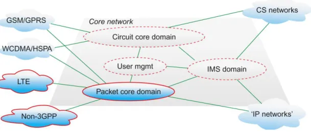
EPS consists of several domains and each of them is a group of logical nodes that interwork to provide a specific set of functions in the network. Figure 3.3.1 illustrates 3GPP specifications which should be implemented by a network.
Figure 3.3.1: 3GPP architecture domains.(Khan 2009)
The four clouds on the left of diagram indicate different RAN domains that can connect to the EPC. These includs the second and third generations of mobile access networks specified by the 3GPP, mostly known as GSM and WCDMA respectively. Of course LTE is the latest mobile broadband radio access as specified by 3GPP. Finally, there is a domain called „non-3GPP access networks‟. This indicates any packet data access network that is not defined by the 3GPP standardization body. The examples are WLAN, fixed network accesses or some combination of these.
The Core Network is parted into many domains (Circuit Core, Packet Core and IMS), which interoperate with each other over several specific interfaces. The Circuit Core domain is composed of units and functions that allow the support for circuit-switched services over GSM and WCDMA.
33
The user management domain provides coordinated subscriber information and supports roaming and mobility between and within the different domains.
The Packet Core domain is composed of units and functions that let support for packet-switched services (mostly IP connectivity) over GSM, WCDMA and HSPA. Therewith, the Packet Core domain also provides support for packet-switched services over LTE and non-3GPP access networks which in whole have nothing to do with the Circuit Core. The packet core domain also supports functions for management and forcing of service and bearer level policies such as QoS.
The IMS domain is composed of units and functions that ensure support for multimedia sessions based on SIP (Session Initiation Protocol), and applies the IP connectivity provided by the functions in the Packet Core domain.
The user management domain is defined for handling of the data related to the subscribers that uses the services of the other domains. Usuallly, in the 3GPP specifications, its not a separate domain . Rather, there are user management functions in the Circuit Core, Packet Core and IMS domains interacting with subscriber data bases defined by 3GPP (Olsson & etc. 2009 pp33-37).
3.3.2 Uu and S1-MME
The S1-MME interface is specified between the eNodeB and the MME and the E-UTRAN-Uu interface is specified between the UE and the eNodeB. The S1-MME interface provides support for functionality such as handover, paging, transparent transport of messages between UE and MME as well as the UE context management. The protocol stack for E-UTRAN-Uu and S1-MME is shown in Figure 3.3.2.1
34
Figure 3.3.2.1 Protocol stack for E-UTRAN-Uu and S1-MME
As it is presented in the Figure 3.3.2.1 the NAS protocols run straight between the UE and the MME while the eNodeB simply acts as a transparent relay. Access stratum (AS) are protocol layers below NAS on E-UTRAN-Uu and S1-MME. The AS protocols on the E-UTRAN-Uu (RRC, RLC, PDCP, MAC and the physical LTE layer) support the NAS protocols by transporting the NAS messages across the E-UTRAN-Uu interface and utilize the Radio Resource Management. Furthermore, the AS protocols on S1-MME (S1-AP, SCTP, IP, etc.) utilize functionality such as handover, paging, UE context management and transparent transport of messages between MME and eNodeB. The NAS layer includes an EPS session management (ESM) protocol and an EPS mobility management (EMM) protocol. The ESM protocol provides procedures for the handling of EPS bearer contexts. The EMM protocol allows procedures for the security for the NAS protocols and control of mobility. This protocol is used for the control of user plane bearers together with the bearer control provided by the access stratum (3GPP TS 24.301 & 3GPP TS 36.410).
3.3.3 eNodeB
↔
Serving GW (S1-U)
The S1-U is the user plane interface carrying user data traffic, received from the terminal, between the eNodeB and Serving GW. For the per bearer user plane tunneling and inter-eNB path switching during handover, S1-U acts as a reference point between the E-UTRAN and S-GW. The GPRS Tunneling Protocol for the User Plane (GTP-U) is used at this reference point ( Akyildiz & D. Gutierrez-Estevez 2010).
35
3.3.4 MME
↔
MME (S10)
S10 - This is a control interface between the MMEs which is exclusively based on GTPv2-C. This interface is used for LTE access only. The main function, which is to transfer the contexts for individual terminals attached to the EPC network and thus sent on a per UE basis, runs over this protocol. This is the reference point between the MME-to-MME information transfer and the MMEs for MME relocation. This reference point provides mobility functions for the intra-E-UTRAN handover/ relocation. In other words, signaling procedures on this interface are triggered by UE mobility. This type of MME relocation in the 3GPP 23.401 is called S1 handover. Hence, S10 is seen as special type of S1 interface and the S1AP is used at this reference point (M. Olsson & etc 2009 p234, 3GPP 23.401).
3.3.5 MME
↔
Serving GW (S11)
The S11 interface is defined between the MME and the Serving GW. Because of the separation of the user and control plane functions the between Serving GW and MME, the S11 interface is used to create a new session, like establishing the necessary resources for the session and then manage these sessions by modifying, deleting and changing any sessions for each PDN connection and for a terminal that has established connection within EPS.
The S11 interface is always activated by some events either directly from the NAS level signaling from the terminal when
1. a device is getting attached with the EPS network or
2. adding new bearers to an existing session, handover cases, or
3. activated during network initiated procedures such as PDN GW-initiated bearer modification procedures.
S11 interface keeps the user and control plane procedures in synchronization for a terminal during the period when the terminal is seen active/attached in the EPS. The S11 interface is used to relocate the Serving GW, in case of handover, when it
36
establishes direct or indirect forwarding tunnel for user plane traffic as well as manages the user data traffic flow (3GPP TS 29.274).
3.3.6 Serving GW ↔ PDN GW (S5/S8)
The S5/S8 interface is specified between the Serving GW and the PDN GW. The S5 interface is used in roaming scenarios when both Serving GW and PDN GW are located in the visited network, or in non-roaming scenarios when the Serving GW is located in the home network. The roaming scenario is also referred to as Local Breakout. The S5 reference point provides user plane tunneling and tunnel management between the S-GW and PDN-S-GW. It is used in case of S-S-GW relocation due to UE mobility and if the S-GW needs to be connected to a non-collocated PDN-GW for the required PDN connectivity. The GTP is the protocol used at this reference point for both the user plane and control plane.
The S8 interface is just a roaming variant of the S5 which is used in roaming scenarios with the PDN GW in the home network and the Serving GW in the visited network. The S8 reference point is used by roaming subscribers only. It is the inter-PLMN reference point providing the user plane and control plane between the S-GW in the Visited PLMN (VPLMN) and the PDN-GW in the Home PLMN (HPLMN). The S8 is the inter-PLMN variant of the S5, based on the GTP as well, and can be compared to the Gp interface defined for the GERAN GPRS. It also utilizes transfer of (QoS) policy and charging control information between the home PCRF and the visited PCRF in order to support the local breakout function (3GPP TS 23.402).
3.3.7 SGSN
↔
MME (S3)
The S3 interface is defined between the S4-based SGSN and the MME for supporting handover to/from 2G/3G radio access network for 3GPP accesses. The functions provided by S3 include transfer of the information related to the terminal that is being handed over, handover/relocation messages and thus the messages are for individual terminal basis. As it is the central point between the MME and SGSN, the SGSN may
37
serve for UTRAN, GERAN, or both of them. On the S3 we can see control-plane-information for user and bearer control-plane-information exchange for inter-3GPP access network mobility (inter-RAT handover) in the idle and/or active state. If the connection was set up originally in the E-UTRAN and is handed over to UTRAN/GERAN the appropriate user plane streams are routed across the S4 reference point. What happens in case the UTRAN/GERAN to E-UTRAN handover depends on the fact whether S-GW acts as an anchor for UTRAN/GERAN traffic or not? If this is true the user plane tunnel can be switched smoothly between S4 and S1-U during the handover. The protocol used at the S3 reference point is the GTP-C (3GPP TS 23.401).
3.3.8 SGSN
↔
Serving GW (S4)
The S4 interface is defined between the SGSN supporting Serving GW and the 2G/3G radio access. It also has equivalent functions as the S11 interface does, but it acts only for the 2G/3G radio access networks. This interface supports only GTPv2-C and in case the 3G network has not enabled direct tunnel for user plane traffic from RNC to/ from Serving GW, it utilizes procedures to enable user plane tunnel between the SGSN and Serving GW (3GPP TS 23.401).
3.3.9 SGSN
↔
SGSN (S16)
The S16 interface is defined between two SGSNs. As in the case of S4, this interface exclusively uses GTPv2-C and is for 2G/3G accesses only when it is on an EPS network. The main functions of this protocol is transferring the contexts of individual terminals, attached to the EPC network and are thus sent on a per UE basis as it was for the S10 interface (3GPP TS 29.303).
38
3.4 Protocol Architecture
The architecture of the radio interface protocol is based on the same architecture defined for the HSPA. The names of the protocols are the same, as well as the functions are similar. Some dissimilarities come from the differences in the multiple access techniques of the LTE and HSPA. Others are related to the fact that the LTE is a packet-only system, meaning that there are no requirements to support the legacy circuit-switched domain.
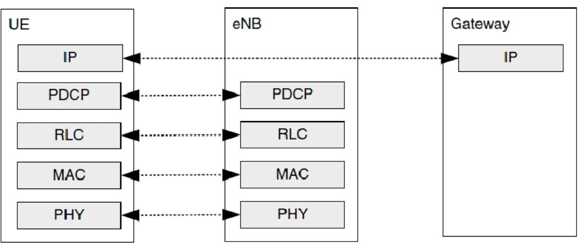
The user plane protocol stack is given in Figure 3.4.1. One can note that the packet data convergence protocol (PDCP) and the radio link control (RLC) layers, which were used to be terminated in RNC on the network side are now terminated in eNB.
Figure 3.4.1. User plane protocol.
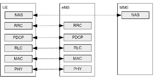
Figure 3.4.2 shows the control plane protocol stack. Here also the RRC functionality originaly implemented in the RNC is now incorporated into eNB. The control plane functions of the RLC and MAC layers are the same as for the user plane. The RRC functions include system information broadcast, radio bearer control, paging, RRC connection management, mobility functions and UE measurement reporting and control. Independently from the non-access stratum (NAS) protocols, all radio interface protocols terminate in the eNodeB on the network side. The NAS protocol terminates in the MME on the network side and at the UE on the terminal side and performs functions
39
such as EPS (evolved packet system) bearer management, authentication and security control, etc. (Rohde & Schwartz).
Figure 3.4.2.Control plane protocol stack.
Packet Data Convergence Protocol (PDCP) performs IP header compression for reducing the number of bits to be transmitted over the radio interface. The header-compression mechanism is based on Robust Header Compression (ROHC). This standardized header-compression algorithm is also used for several other mobile-communication technologies. It is also responsible for ciphering. The PDCP protocol performs the corresponding deciphering and decompression operations at the receiver side. There is only one PDCP entity per radio bearer configured for a terminal. From the control plane, the PDCP is responsible for the integrity protection of the transmitted data, as well as in-sequence delivery and duplicate removal for handover (2009 EventHelix.com).
Radio-Link Control (RLC) is responsible for duplicate detection, segmentation/concatenation, in-sequence delivery to higher layers and retransmission handling. The RLC utilizes services to the PDCP in the form of radio bearers. There is only one configured RLC entity per radio bearer for a terminal (3GPP TS 36.322).
Medium-Access Control (MAC) utilizes hybrid-ARQ retransmissions, uplink and downlink scheduling and multiplexing of logical channels. For both uplink and
40
downlink, the scheduling functionality is located in the eNodeB. The hybrid-ARQ protocol is also present in the MAC protocol for both the transmitting and receiving ends. The MAC provides, in the form of logical channels, services to the RLC (3GPP TS 36.321).
Physical Layer (PHY) utilizes coding/decoding, multi-antenna mapping, modulation/demodulation, and other typical physical-layer functions. The physical layer provides services to the MAC layer in the form of transport channels (3GPP TS 36.201).
Radio Resource Control (RRC) is responsible for managing the RAN-related procedures. This may include broadcast of system information necessary for the terminal to be able to communicate with a cell. It also handles transmission of paging messages originated from the MME for notifying the terminal about incoming connection requests. Paging is used in the RRC_IDLE state when the terminal is not connected to a particular cell. RRC also handles Connection management, including setting up bearers and mobility within LTE. This includes Mobility functions such as cell (re)selection measurement configuration and reporting(UTRAN Radio Interface protocols).
Non-Access Stratum (NAS) control-plane functionality which is handled by the MME, is responsible for the EPS bearer authentication, security, management and other idle-mode procedures such as paging. NAS is also responsible for assigning to a terminal an IP address (3GPP TS 24.301).
41
4.LTE RADIO-INTERFACE PHYSICAL LAYER
The long term evolution (LTE) of the Universal Mobile Telecommunications System‟s (UMTS) Terrestrial Radio Access (UTRA) has been termed E-UTRA. A continuous work activity started in April 2008 in 3GPP focuses on the enhanced version of LTE, the LTE-Advanced. E-UTRA of LTE system provides spectrum flexibility with bandwidths between 1.25 MHz and 20 MHz. Peak data rates range up to 100 Mbit/s in the downlink and 50 Mbit/s in the uplink at a maximum bandwidth of 20 MHz. LTE-Advanced aims to further enhance the LTE system to fulfill and even surpass the IMT-Advanced (International Mobile Telecommunications) requirements given by ITU for the 4G mobile communication system. With spectrum aggregation, transmission relay, cooperative communication, cognitive radio technologies and scalable system bandwidth up to 100 MHz, LTE-Advanced is designed to meet the peak data rate of 1 Gbit/s. The key technologies in E-UTRA systems are OFDMA (Orthogonal Frequency Division Multiple Access) in the downlink and SC-FDMA (Single Carrier Frequency Division Multiple Access) for uplink transmission.
4.1 LTE-Advanced Requirements
The most important requirements requirements for LTE-Advanced are the following Data Rate:
Peak data rate of 1 Gbps for downlink (DL) and 500 Mbps for uplink (UL). Latency:
In LTE-Advanced in the C-plane the transition time from Idle to Connected should be lower than 50ms. In the active state, a dormant user should take less than 10ms to get synchronized and the scheduler should reduce the U-plane latency at maximum.
42 Peak Spectral Efficiency:
The system should support downlink peak spectral efficiency up to 30 bps/Hz and uplink peak spectral efficiency of 15 bps/Hz with an antenna configuration of 8 × 8 or less in DL and 4 × 4 or less in UL.
Average Cell Spectral Efficiency:
The 3GPP defined a base coverage urban scenario with inter-site distance of 500m and pedestrian users. Assuming this scenario, average user spectral efficiency in DL must be 2.4 bps/Hz/cell with MIMO 2 × 2, 2.6 bps/Hz/cell with MIMO 4 × 2 and 3.7 bps/Hz/cell with MIMO 4 × 4, whereas in UL the target average spectral efficiency is 1.2 bps/Hz/cell and 2.0 bps/Hz/cell with SIMO 1×2 and MIMO2×4, respectively.
Spectral Efficiency of Cell Edge:
In the same scenario with 10 users, cell edge user spectral efficiency will be 0.07 bps/Hz/cell/user in DL 2 × 2, 0.09 in DL 4 × 2 and 0.12 in DL 4 × 4. In the UL, this cell edge user spectral efficiency must be 0.04 bps/Hz/cell/user with SIMO 1 × 2 and 0.07 with MIMO 2 × 4.
Bandwidth:
In terms of spectrum flexibility, the LTE-Advanced system will support scalable bandwidth and spectrum aggregation with transmission bandwidths up to 100MHz in DL and UL.
Mobility:
The mobility and coverage requirements are identical to LTE Release 8. There are only differences with indoor deployments that need additional care in LTE-Advanced (Femtocells deployment). LTE-Advanced must guarantee backward compatibility and interworking with LTE and other networks.
43
4.2 LTE-Advanced Frame Structure
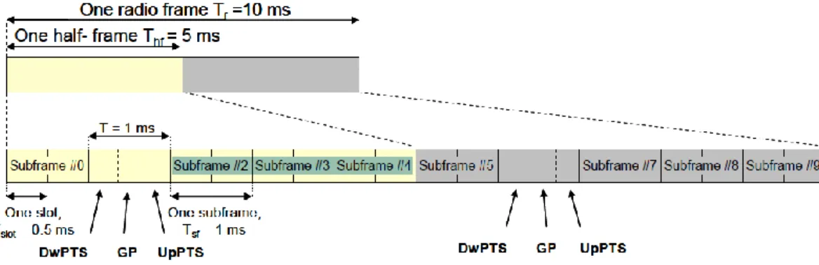
The duplexing of uplink and downlink transmissions is normally carried out in frequency or time domain and is known as Frequency Division Duplexing (FDD) or Time Division Duplexing (TDD), respectively. Two frame structure types are defined for E-UTRA: frame structure type 1 for FDD mode, and frame structure type 2 for TDD mode. The frame structure defines the frame, slot, and symbol in the time domain. In FDD mode each radio frame is 10 ms long and consists of 10 subframes as shown in Figure 4.2.1. Each subframe contains two slots. The Slots consist of 6 or 7 ODFM symbols, which depends on the employed cyclic prefix. There are two types of CP, the normal and the extended. The total number of available subcarriers depends on the overall transmission bandwidth of the system(Rohde&Schwartz).
Figure 4.2.1: Frame structure FDD(Rohde&Schwartz)
A resource block which is the smallest unit in time and frequency is defined to consist of 12 sub-carriers in frequency and 14 continuous symbols in time domain. This makes one resource block to span 180 kHz in frequency and 1ms time respectively Table 4.2.1.
44
Table 4.2.1 Available Bandwidth is divided into Physical Resource Blocks
The sub-frame is also the minimum transmission time interval (TTI). The choice of short TTI helps to achieve the requirements of low latency. In FDD Both the uplink and the downlink have the same frame structure but they use different spectra (Zyren2007). For voice transmission, where the uplink/downlink traffic is symmetric, the choice of FDD is suitable due to the symmetry in the two channels. Therefore, it is entirely used in the 2G and 3G networks.
TDD Frame structure consists of two 5 ms half-frames for a total duration of 10 ms and is for 5 ms switch-point periodicity. Subframes consist of either an uplink or downlink transmission. For separating uplink and downlink, a special subframe which contain the downlink and uplink pilot timeslots (DwPTS and UpPTS) separated by a transmission gap guard period (GP) exists. (Sánchez, D. Morales-Jiménez).
45
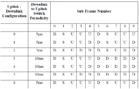
There are seven uplink/downlink configurations used for either 5ms or 10ms point periodicities. A special sub-frame exists in both half frames in case of 5ms switch-point periodicity whereas, for 10ms switch-switch-point periodicity the special frame exists only in the first half-frame. In case of 10 ms switch-point periodicity the special subframe exists in the first half frame only. Subframes 0 and 5 and DwPTS are always reserved for downlink transmission. UpPTS and the subframe immediately following the special subframe are always reserved for uplink transmission. Table 4.2.2 shows the supported uplink-downlink configurations, where “D” denotes a subframe reserved for downlink transmission, “U” denotes a subframe reserved for uplink transmission, and “S” denotes the special subframe (Rohde&Schwartz).
Table 4.2.2 Uplink-Downlink configurations for LTE TDD
TDD has attracted much interest from a research point of view because it allows uplink and downlink transmission to share the same channel at different times, and thus can be adapted according to the traffic condition. TDD requires a guard period to separate the two transmissions. If the transmissions from neighboring cells are not fully aligned, a base station may receive interference from the downlink transmission of its neighboring base stations, and vice versa. In many situations, this mutual interference significantly
46
penalizes the uplink performance due to the relatively low uplink transmit power. (Wang 2010)
4.3 DownLink
The LTE PHY specification is designed to support bandwidths from 1.25 MHz to 20 MHz and up to 100Mhz with Carrier Aggregation. OFDM was selected as the basic modulation scheme because of its robustness in the presence of multipath fading. Downlink multiplexing is accomplished via OFDMA
The overall motivation for OFDMA in LTE and in other systems has been due to the following properties: (Holma& etc 2009 pp 67-70)
•
good performance in frequency selective fading channels;•
low complexity of base-band receiver;•
good spectral properties and handling of multiple bandwidths;•
link adaptation and frequency domain scheduling;•
compatibility with advanced receiver and antenna technologies.4.4 OFDMA (Orthogonal Frequency Division Multiple Access)
The downlink transmission scheme for both E-UTRA FDD and TDD modes is based on conventional OFDM. In past years Orthogonal Frequency-Division Multiplexing (OFDM) has become known as a successful air-interface technique. In Orthogonal Frequency Division Multiplexing the Frequency-Domain (FD), the bandwidth is divided into a number of non-overlapping subchannels, each of which carries a specific