VENTILATION, HEATER & AIR CONDITIONER
C
D
E
F
G
H
J
K
L
M
SECTION
HAC
A
B
HAC
N
O
P
CONTENTS
HEATER & AIR CONDITIONING CONTROL SYSTEM
AUTOMATIC AIR CONDITIONING
BASIC INSPECTION ...
5DIAGNOSIS AND REPAIR WORK FLOW ...
5Work Flow ...
5INSPECTION ...
8Description & Inspection ...
8AUXILIARY MECHANISM ...
10Temperature Setting Trimmer ...
10Inlet Port Memory Function ...
11SYSTEM DESCRIPTION ...
12COMPRESSOR CONTROL FUNCTION ...
12Description ...
12Component Parts Location ...
13Component Description ...
13AUTOMATIC AIR CONDITIONING SYSTEM ....
15System Diagram ...
15System Description ...
15Component Parts Location ...
24Component Description ...
24DIAGNOSIS SYSTEM (A/C AUTO AMP.) ...
26Diagnosis Description ...
26DIAGNOSIS SYSTEM (BCM) (WITH
INTELLI-GENT KEY SYSTEM) ...
30COMMON ITEM ...
30COMMON ITEM : CONSULT-III Function (BCM -
COMMON ITEM) ...
30AIR CONDITIONER ...
31AIR CONDITIONER : CONSULT-III Function
(BCM - AUTO AIR CONDITIONER) ...
31DIAGNOSIS SYSTEM (BCM) (WITHOUT
IN-TELLIGENT KEY SYSTEM) ...
33COMMON ITEM ...
33COMMON ITEM : CONSULT-III Function (BCM -
COMMON ITEM) ...
33AIR CONDITIONER ...
33AIR CONDITIONER : CONSULT-III Function
(BCM - AUTO AIR CONDITIONER) ...
34DTC/CIRCUIT DIAGNOSIS ...
35AMBIENT SENSOR ...
35Description ...
35Diagnosis Procedure ...
35Component Inspection ...
36IN-VEHICLE SENSOR ...
38Description ...
38Diagnosis Procedure ...
38Component Inspection ...
39INTAKE SENSOR ...
41Description ...
41Diagnosis Procedure ...
41Component Inspection ...
42SUNLOAD SENSOR ...
43Description ...
43Diagnosis Procedure ...
43Component Inspection ...
44AIR MIX DOOR MOTOR ...
46Description ...
46Diagnosis Procedure ...
46Component Inspection ...
47MODE DOOR MOTOR ...
49Description ...
49Diagnosis Procedure ...
49Component Inspection ...
50INTAKE DOOR MOTOR ...
52Description ...
52Component Inspection ...
55BLOWER MOTOR ...
56Description ...
56Component Function Check ...
56Diagnosis Procedure ...
56Component Inspection ...
59MAGNET CLUTCH ...
61Description ...
61Component Function Check ...
61Diagnosis Procedure ...
61A/C ON SIGNAL ...
62Component Function Check ...
62Diagnosis Procedure ...
62BLOWER FAN ON SIGNAL ...
64Component Function Check ...
64Diagnosis Procedure ...
64POWER SUPPLY AND GROUND CIRCUIT ...
66A/C AUTO AMP. ...
66A/C AUTO AMP. : Diagnosis Procedure ...
66BCM (BODY CONTROL SYSTEM) (WITH
INTEL-LIGENT KEY SYSTEM) ...
67BCM (BODY CONTROL SYSTEM) (WITH
INTEL-LIGENT KEY SYSTEM) : Diagnosis Procedure ...
67BCM (BODY CONTROL SYSTEM) (WITHOUT
IN-TELLIGENT KEY SYSTEM) ...
68BCM (BODY CONTROL SYSTEM) (WITHOUT
INTELLIGENT KEY SYSTEM) : Diagnosis
Proce-dure ...
68A/C AUTO AMP. ...
70Description ...
70Component Function Check ...
70Diagnosis Procedure ...
70ECU DIAGNOSIS INFORMATION ...
71A/C AUTO AMP. ...
71Reference Value ...
71Wiring Diagram - AUTOMATIC AIR
CONDITION-ING SYSTEM - ...
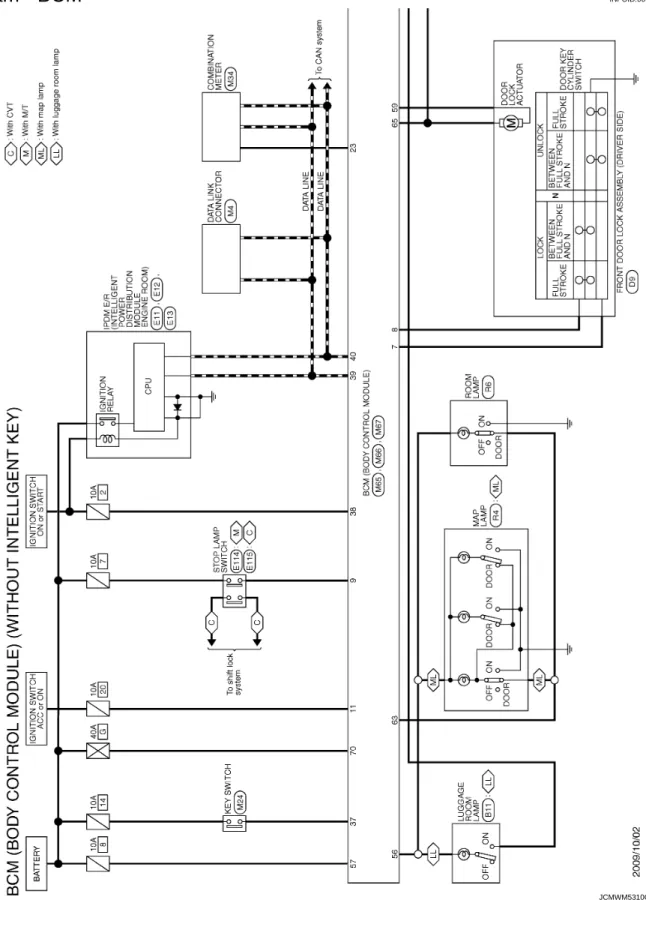
74BCM (BODY CONTROL MODULE) ...
82BCM (BODY CONTROL SYSTEM) (WITH
INTEL-LIGENT KEY SYSTEM) ...
82BCM (BODY CONTROL SYSTEM) (WITH
INTEL-LIGENT KEY SYSTEM) : Reference Value ...
82BCM (BODY CONTROL SYSTEM) (WITH
INTEL-LIGENT KEY SYSTEM) : Wiring Diagram - BCM - ..
102BCM (BODY CONTROL SYSTEM) (WITH
INTEL-LIGENT KEY SYSTEM) : Fail-safe ...
107BCM (BODY CONTROL SYSTEM) (WITH
INTEL-LIGENT KEY SYSTEM) :
DTC Inspection Priority Chart ...
109BCM (BODY CONTROL SYSTEM) (WITH
INTEL-LIGENT KEY SYSTEM) : DTC Index ...
111BCM (BODY CONTROL SYSTEM) (WITHOUT
IN-TELLIGENT KEY SYSTEM) ...
112BCM (BODY CONTROL SYSTEM) (WITHOUT
INTELLIGENT KEY SYSTEM) : Reference Value .
112BCM (BODY CONTROL SYSTEM) (WITHOUT
INTELLIGENT KEY SYSTEM) : Wiring Diagram -
BCM - ...
127BCM (BODY CONTROL SYSTEM) (WITHOUT
INTELLIGENT KEY SYSTEM) : Fail-safe ...
131BCM (BODY CONTROL SYSTEM) (WITHOUT
INTELLIGENT KEY SYSTEM) :
DTC Inspection Priority Chart ...
132BCM (BODY CONTROL SYSTEM) (WITHOUT
INTELLIGENT KEY SYSTEM) : DTC Index ...
132SYMPTOM DIAGNOSIS ...
134AUTOMATIC AIR CONDITIONING SYSTEM ..
134Diagnosis Chart By Symptom ...
134INSUFFICIENT COOLING ...
135Description ...
135Diagnosis Procedure ...
135INSUFFICIENT HEATING ...
137Description ...
137Diagnosis Procedure ...
137COMPRESSOR DOSE DOT OPERATE ...
138Description ...
138Diagnosis Procedure ...
138MEMORY FUNCTION DOES NOT OPERATE ..
140Description ...
140Inspection Procedure ...
140PRECAUTION ...
141PRECAUTIONS ...
141Precaution for Supplemental Restraint System
(SRS) "AIR BAG" and "SEAT BELT
PRE-TEN-SIONER" ...
141Precaution Necessary for Steering Wheel
Rota-tion after Battery Disconnect ...
141REMOVAL AND INSTALLATION ...
143A/C CONTROL (A/C AUTO AMP.) ...
143Exploded View ...
143Removal and Installation ...
143AMBIENT SENSOR ...
144Exploded View ...
144Removal and Installation ...
144IN-VEHICLE SENSOR ...
145Exploded View ...
145C
D
E
F
G
H
J
K
L
M
A
B
HAC
N
O
P
SUNLOAD SENSOR ...
146Exploded View ...
146Removal and Installation ...
146INTAKE SENSOR ...
147Exploded View ...
147Removal and Installation ...
147REFRIGERANT PRESSURE SENSOR ...
148Exploded View ...
148Removal and Installation ...
148POWER TRANSISTOR ...
150Exploded View ...
150Removal and Installation ...
150DOOR MOTOR ...
151Exploded View ...
151INTAKE DOOR MOTOR ...
152INTAKE DOOR MOTOR : Removal and
Installa-tion ...
152MODE DOOR MOTOR ...
152MODE DOOR MOTOR : Removal and Installation
..
153AIR MIX DOOR MOTOR ...
153AIR MIX DOOR MOTOR : Removal and
Installa-tion ...
153MANUAL AIR CONDITIONING
BASIC INSPECTION ...
154DIAGNOSIS AND REPAIR WORKFLOW ...
154Work Flow ...
154INSPECTION ...
156Description & Inspection ...
156SYSTEM DESCRIPTION ...
158COMPRESSOR CONTROL FUNCTION ...
158Description ...
158Component Part Location ...
159Component Description ...
159MANUAL AIR CONDITIONING SYSTEM ...
161System Diagram ...
161System Description ...
161Component Part Location ...
165Component Description ...
165DIAGNOSIS SYSTEM (BCM) ...
167COMMON ITEM ...
167COMMON ITEM : CONSULT-III Function (BCM -
COMMON ITEM) ...
167AIR CONDITIONER ...
167AIR CONDITIONER : CONSULT-III Function ...
168DTC/CIRCUIT DIAGNOSIS ...
169POWER SUPPLY AND GROUND CIRCUIT ..
169BCM ...
169BCM : Diagnosis Procedure ...
169INTAKE DOOR MOTOR ...
170Description ...
170Diagnosis Procedure ...
170Component Inspection ...
171THERMO CONTROL AMPLIFIER ...
172Description ...
172Component Function Check ...
172Diagnosis Procedure ...
172BLOWER MOTOR ...
175Description ...
175Diagnosis Procedure ...
175Component Inspection ...
177MAGNET CLUTCH ...
179Description ...
179Component Function Check ...
179Diagnosis Procedure ...
179A/C SWITCH ...
180Description ...
180Component Function Check ...
180Diagnosis Procedure ...
180DEFROSTER POSITION SIGNAL ...
182Description ...
182Component Function Check ...
182Diagnosis Procedure ...
182A/C INDICATOR ...
184Component Function Check ...
184Diagnosis Procedure ...
184BLOWER FAN ON SIGNAL ...
186Component Function Check ...
186Diagnosis Procedure ...
186MANUAL AIR CONDITIONING SYSTEM ...
188Wiring Diagram — MANUAL AIR
CONDITION-ING SYSTEM — ...
188ECU DIAGNOSIS INFORMATION ...
194BCM (BODY CONTROL MODULE) ...
194Reference Value ...
194Wiring Diagram - BCM - ...
209Fail-safe ...
212DTC Inspection Priority Chart ...
213DTC Index ...
213SYMPTOM DIAGNOSIS ...
215MANUAL AIR CONDITIONING SYSTEM ...
215Diagnosis Chart By Symptom ...
215Description ...
217Diagnosis Procedure ...
217INSUFFICIENT HEATING ...
218Description ...
218Diagnosis Procedure ...
218COMPRESSOR DOSE DOT OPERATE ...
219Description ...
219Diagnosis Procedure ...
219PRECAUTION ...
221PRECAUTIONS ...
221Precaution for Supplemental Restraint System
(SRS) "AIR BAG" and "SEAT BELT
PRE-TEN-SIONER" ...
221Precaution Necessary for Steering Wheel
Rota-tion after Battery Disconnect ...
221REMOVAL AND INSTALLATION ...
223A/C CONTROL ...
223Exploded View ...
223Removal and Installation ...
223THERMO CONTROL AMPLIFIER ...
225Exploded View ...
225Removal and Installation ...
225REFRIGERANT PRESSURE SENSOR ...
226Exploded View ...
226Removal and Installation ...
226BLOWER FAN RESISTOR ...
228Exploded View ...
228Removal and Installation ...
228INTAKE DOOR MOTOR ...
229Exploded View ...
229Removal and Installation ...
229DOOR CABLE ...
230Exploded View ...
230MODE DOOR CABLE ...
231MODE DOOR CABLE : Removal and Installation .
231AIR MIX DOOR CABLE ...
231AIR MIX DOOR CABLE : Removal and Installation
.
231DIAGNOSIS AND REPAIR WORK FLOW
< BASIC INSPECTION >
[AUTOMATIC AIR CONDITIONING]
C
D
E
F
G
H
J
K
L
M
A
B
HAC
N
O
P
BASIC INSPECTION
DIAGNOSIS AND REPAIR WORK FLOW
Work Flow
INFOID:0000000005490026OVERALL SEQUENCE
DETAILED FLOW
< BASIC INSPECTION >
[AUTOMATIC AIR CONDITIONING]
DIAGNOSIS AND REPAIR WORK FLOW
1.
INTERVIEW FOR MALFUNCTION
Interview the symptom to the customer.
>> GO TO 2.
2.
SYMPTOM CHECK
Check the symptom from the customer's information.
>> GO TO 3.
3.
BASIC INSPECTION
Check the operation of each part. Check that any symptom occurs other than the interviewed symptom.
>> GO TO 4.
4.
SELF-DIAGNOSIS WITH ON BOARD DIAGNOSIS SYSTEM
Perform the self-diagnosis with on board diagnosis. Check that whether malfunction result is detected or not.
Refer to
HAC-26, "Diagnosis Description"
.
Is any malfunction result detected?
YES
>> GO TO 5.
NO
>> GO TO 6.
5.
TROUBLE DIAGNOSIS BY MALFUNCTION
Perform the trouble diagnosis for the detected malfunction result. Specify the malfunction part.
>> GO TO 6.
6.
SELF-DIAGNOSIS WITH CONSULT-III
Perform the self-diagnosis with CONSULT-III. Check that any DTC is detected.
Is any DTC detected?
YES
>> GO TO 7.
NO
>> GO TO 8.
7.
TROUBLE DIAGNOSIS BY DTC
Perform the trouble diagnosis for the detected DTC. Specify the malfunctioning part.
>> GO TO 8.
8.
SYMPTOM DIAGNOSIS
Perform the symptom diagnosis. Specify the malfunctioning part.
>> GO TO 9.
9.
MALFUNCTION PART REPAIR
Repair or replace the malfunctioning part.
>> GO TO 10.
10.
REPAIR CHECK (SELF-DIAGNOSIS WITH ON BOARD DIAGNOSIS AND CONSULT-III)
Perform the self-diagnoses with on board diagnosis and CONSULT-III. Check that any DTC or malfunction
result is not detected. Erase DTC if DTC is detected before the repair. Check that DTC is not detected again.
Is any or malfunction result or DTC detected?
YES-1 >> If malfunction result is detected, GO TO 5.
YES-2 >> If DTC is detected, GO TO 7.
DIAGNOSIS AND REPAIR WORK FLOW
< BASIC INSPECTION >
[AUTOMATIC AIR CONDITIONING]
C
D
E
F
G
H
J
K
L
M
A
B
HAC
N
O
P
11.
REPAIR CHECK (OPERATION CHECK)
Check the operation of each part.
Does it operate normally?
YES
>> INSPECTION END
NO
>> GO TO 3.
< BASIC INSPECTION >
[AUTOMATIC AIR CONDITIONING]
INSPECTION
INSPECTION
Description & Inspection
INFOID:0000000005490027DESCRIPTION
The purpose of the operational check is to check that the individual system operates normally.
1.
CHECK MEMORY FUNCTION
1.
Start the engine.
2.
Set the temperature to 32
°
C (90
°
F) by operating the temperature control switch.
3.
Press OFF switch.
4.
Turn ignition switch OFF.
5.
Turn ignition switch ON.
6.
Press AUTO switch.
7.
Check that the set temperature is maintained.
Is the inspection result normal?
YES
>> GO TO 2.
NO
>> Memory function malfunction. Refer to
HAC-140, "Inspection Procedure"
.
2.
CHECK BLOWER MOTOR
1.
Start the engine.
2.
Operate the fan control switch. Check that the fan speed changes. Check the operation for all fan speeds.
3.
Leave blower on maximum speed.
Is the inspection result normal?
YES
>> GO TO 3.
NO
>> Blower motor system malfunction. Refer to
HAC-56, "Diagnosis Procedure"
.
3.
CHECK DISCHARGE AIR
1.
Operate MODE switch and DEF switch to each position.
2.
Check that the air outlets change according to each indicated air outlet by placing a hand in front of the
outlets. Refer to
VTL-2, "System Description"
.
Is the inspection result normal?
YES
>> GO TO 4.
NO
>> Mode door system malfunction. Refer to
HAC-49, "Diagnosis Procedure"
.
4.
CHECK INTAKE AIR
1.
Press REC switch to set the air outlet to recirculation.
2.
The REC indicator turns ON.
3.
Listen to intake sound and confirm air inlets change.
4.
Press FRE switch again to set the air outlet to fresh air intake.
5.
The FRE indicator turns ON.
6.
Listen to intake sound and confirm air inlets change.
Is the inspection result normal?
YES
>> GO TO 5.
NO
>> Intake door system malfunction. Refer to
HAC-52, "Diagnosis Procedure"
.
5.
CHECK A/C SWITCH
1.
Press the A/C switch.
2.
Check that the indicator of the A/C switch turns ON. Check visually and by sound that the compressor
operates.
3.
Press the A/C switch again.
4.
Check that the indicator of the A/C switch turns OFF. Check that the compressor stops.
Is the inspection result normal?
YES
>> GO TO 6.
NO
>> Magnet clutch system malfunction. Refer to
HAC-61, "Diagnosis Procedure"
.
INSPECTION
< BASIC INSPECTION >
[AUTOMATIC AIR CONDITIONING]
C
D
E
F
G
H
J
K
L
M
A
B
HAC
N
O
P
6.
CHECK DISCHARGE AIR TEMPERATURE
Operate the temperature control switch. Check that the discharge air temperature changes.
Is the inspection result normal?
YES
>> GO TO 7.
NO
>> Air mix door system malfunction. Refer to
HAC-46, "Diagnosis Procedure"
.
7.
CHECK TEMPERATURE DECREASE
1.
Operate the compressor.
2.
Operate the temperature control switch to lower temperature setting at 18
°
C (60
°
F).
3.
Check that the cool air blows from the outlets.
Is the inspection result normal?
YES
>> GO TO 8.
NO
>> Insufficient cooling. Refer to
HAC-135, "Diagnosis Procedure"
.
8.
CHECK TEMPERATURE INCREASE
1.
Turn temperature control switch to raise temperature setting at 32
°
C (90
°
F) after warming up the engine.
2.
Check that warm air blows from outlets.
Is the inspection result normal?
YES
>> GO TO 9.
NO
>> Insufficient heating. Refer to
HAC-137, "Diagnosis Procedure"
.
9.
CHECK AUTO MODE
1.
Press AUTO switch to confirm that “AUTO” is indicated on the display.
2.
Operate the temperature control switch to check that the fan speed or air outlet changes (the air flow
perature or fan speed varies depending on the ambient temperature, in-vehicle temperature, and set
tem-perature).
Is the inspection result normal?
YES
>> INSPECTION END
< BASIC INSPECTION >
[AUTOMATIC AIR CONDITIONING]
AUXILIARY MECHANISM
AUXILIARY MECHANISM
Temperature Setting Trimmer
INFOID:0000000005490028DESCRIPTION
If the temperature felt by the customer is different than the air flow temperature controlled by the temperature
setting, the A/C auto amp. control temperature can be adjusted to compensate for the temperature setting.
OPERATING PROCEDURES
1.
Begin self-diagnosis STEP 5 mode. Refer to
HAC-26, "Diagnosis Description"
.
2.
Press fan control switch (up: +) to enter the set temperature setting trimmer mode from STEP 5, and then
display shows “0
°
C (0
°
F)”.
3.
The indication temperature will be changed by 1
°
C (1
°
F) in range of
−
3
°
C (
−
6
°
F) to +3
°
C (+6
°
F) by
press-ing the temperature control switch each time.
USA models
Canada models
NOTE:
• When
−
3
°
C (
−
6
°
F) is corrected on the temperature setting set as 25
°
C (75
°
F), the temperature controlled by
A/C auto amp. is 25
°
C (75
°
F)
−
3
°
C (6
°
F) = 22.0
°
C (69
°
F) and the temperature becomes lower than the
tem-perature setting.
• When the battery cable is disconnected from the negative terminal or when the battery voltage becomes 10
V or less, the setting of the difference between the set temperature and control temperature may be
can-celled.
Temperature control switch operation Display Correction (°F)
6 time pressing 6 +6 5 time pressing 5 +5 4 time pressing 4 +4 3 time pressing 3 +3 2 time pressing 2 +2 1 time pressing 1 +1 Initial status 0 0
1 time pressing AUTO 1 −1
2 time pressing AUTO 2 −2
3 time pressing AUTO 3 −3
4 time pressing AUTO 4 −4
5 time pressing AUTO 5 −5
6 time pressing AUTO 6 −6
Temperature control switch operation Display Correction (°C)
3 time pressing 3 +3
2 time pressing 2 +2
1 time pressing 1 +1
Initial status 0 0
1 time pressing AUTO 1 −1
2 time pressing AUTO 2 −2
AUXILIARY MECHANISM
< BASIC INSPECTION >
[AUTOMATIC AIR CONDITIONING]
C
D
E
F
G
H
J
K
L
M
A
B
HAC
N
O
P
Inlet Port Memory Function
INFOID:0000000005490029DESCRIPTION
• Inlet port setting can be memorized when ignition switch is turned OFF.
• Inlet port setting can be selected from FRE (fresh air intake), REC (recirculation), or “Do not perform the
memory” when ignition switch is turned ON.
OPERATING PROCEDURES
1.
Begin self-diagnosis STEP 5 mode. Refer to
HAC-26, "Diagnosis Description"
.
2.
Press fan control switch (up: +) two times to change the mode to the temperature setting trimmer from
self-diagnosis STEP 5, and then the display shows “70”.
3.
The setting of inlet port memory function can be selected from “70” to “73” by pressing the FRE switch.
*: Initial status NOTE:
• When FRE switch is pressed four times, display shows "70" again.
• When the battery cable is disconnected from the negative terminal or when the battery voltage becomes 10 V or less, the setting of the inlet port memory function may be cancelled.
FRE switch operation Display Memory function
Manual REC Manual FRE
— 70* Shall be memorized Shall not be memorized
1 time pressing 71 Shall not be memorized Shall not be memorized
2 time pressing 72 Shall be memorized Shall be memorized
< SYSTEM DESCRIPTION >
[AUTOMATIC AIR CONDITIONING]
COMPRESSOR CONTROL FUNCTION
SYSTEM DESCRIPTION
COMPRESSOR CONTROL FUNCTION
Description
INFOID:0000000005490030PRINCIPLE OF OPERATION
Functional Circuit Diagram
Functional Initial Inspection Chart
×: Applicable
L (1) : Fan ON signal CAN (1) : A/C ON switch signal
: Blower fan ON signal
L (2) : A/C switch signal CAN (2) : A/C compressor request signal
JPIIA1651GB
Control unit Diagnosis item Location
A B C D E F
A/C auto amp. On board self-diagnosis × — — — — —
BCM “BCM-AIR COND”
Self-diagnosis — — × — — —
Data monitor — × — — — —
ECM “ENGINE”
Self-diagnosis
(CAN communication line) — — — — × —
Data monitor — — × × — —
IPDM E/R “IPDM E/R”
Self-diagnosis
(CAN communication line) — — — — — ×
Data monitor — — — — × —
COMPRESSOR CONTROL FUNCTION
< SYSTEM DESCRIPTION >
[AUTOMATIC AIR CONDITIONING]
C
D
E
F
G
H
J
K
L
M
A
B
HAC
N
O
P
Component Parts Location
INFOID:0000000005490031Component Description
INFOID:00000000054900321. Sunload sensor 2. Ambient sensor 3. Magnet clutch
4. Refrigerant pressure sensor 5. A/C control (A/C auto amp.) 6. In-vehicle sensor
7. Blower motor 8. Mode door motor 9. Power transistor
10. Intake door motor 11. Air mix door motor 12. Intake sensor A. Located in the right side of A/C
unit assembly
B. Located in the back of A/C unit assembly
C. Located in left side of A/C unit assembly
D. Located on the evaporator
JPIIA1719ZZ
Component Description
Sunload sensor HAC-43, "Description"
< SYSTEM DESCRIPTION >
[AUTOMATIC AIR CONDITIONING]
COMPRESSOR CONTROL FUNCTION
Magnet clutch HAC-61, "Description"
Refrigerant pressure sensor EC-415, "Description"
A/C control (A/C auto amp.) HAC-70, "Description"
In-vehicle sensor HAC-38, "Description"
Blower motor HAC-56, "Description"
Air mix door motor HAC-46, "Description"
Power transistor HAC-56, "Description"
Intake sensor HAC-41, "Description"
Mode door motor HAC-49, "Description"
Intake door motor HAC-52, "Description"
AUTOMATIC AIR CONDITIONING SYSTEM
< SYSTEM DESCRIPTION >
[AUTOMATIC AIR CONDITIONING]
C
D
E
F
G
H
J
K
L
M
A
B
HAC
N
O
P
AUTOMATIC AIR CONDITIONING SYSTEM
System Diagram
INFOID:0000000005490033System Description
INFOID:0000000005490034OUTLINE
• Automatic air conditioner system is controlled by each function of A/C auto amp., ECM, BCM and IPDM E/R.
Control by A/C auto amp.
- Air outlet control
- Temperature control
- Air inlet control
- Air flow control
- Compressor control
- Door motor control (LCU communication control)
Control by BCM
- Compressor control
Control by ECM
- Cooling fan control. Refer to
EC-61, "System Description"
.
- Air conditioning cut control. Refer to
EC-45, "System Description"
.
- Compressor control
Control by IPDM E/R
- Relay control. Refer to
PCS-4, "System Description"
(WITH I-KEY) or
PCS-35, "System Description"
(WITH-OUT I-KEY).
- Cooling fan control. Refer to
PCS-4, "System Description"
(WITH I-KEY) or
PCS-35, "System Description"
(WITHOUT I-KEY).
• Each A/C system can be operated by A/C controller (built-in A/C auto amp.).
< SYSTEM DESCRIPTION >
[AUTOMATIC AIR CONDITIONING]
AUTOMATIC AIR CONDITIONING SYSTEM
OPERATION
Controller (A/C Control)
For USA
For Canada
Switch Operation
JPIIA1668ZZ
1. DEF switch 2. Fan control switch 3. OFF switch
4. MODE switch 5. REC switch 6. FRE switch
7. A/C switch 8. Temperature control switch 9. AUTO switch
10. Rear window defogger switch 11. A/C display
JPIIA1653ZZ
1. DEF switch 2. Fan control switch 3. OFF switch
4. MODE switch 5. REC switch 6. FRE switch
7. A/C switch 8. Temperature control switch 9. AUTO switch
AUTOMATIC AIR CONDITIONING SYSTEM
< SYSTEM DESCRIPTION >
[AUTOMATIC AIR CONDITIONING]
C
D
E
F
G
H
J
K
L
M
A
B
HAC
N
O
P
DEF switch• DEF switch indicator is turned ON ⇔ OFF by pressing DEF switch each time.
• When DEF switch is operated while air conditioner system is activated, the system becomes the following states.
- Compressor: ON - Air inlet: Fresh air intake
- Blower fan: Auto control (if blower fan is set to manual mode before pressing DEF switch, it be-comes manual mode)
- When DEF mode set to OFF, air conditioner system returns previous condition which is set to DEF mode.
• When DEF switch is operated while air conditioner system is inactivation, the system becomes the following states.
- Air conditioner system: ON - Compressor: ON
- Air inlet: Fresh air intake - Blower fan: Auto control
• When DEF mode set to OFF, all air conditioner system is OFF. NOTE:
When DEF mode is set to ON during auto control of air conditioner system, the system becomes man-ual control.
Fan control switch
Fan speed is selected within a range between 1st – 7th speed by pressing this switch. NOTE:
• When air conditioner system is OFF, air conditioner system is set to ON by pressing this switch. • When fan control switch is operated during auto control of air conditioner system, the system
be-comes manual mode.
OFF switch
• Air conditioner system is turned OFF by pressing this switch.
• When the air conditioner system becomes OFF, air inlet and outlet are set as follows: - Air inlet: FRE (except REC is manually selected)
- Air outlet: FOOT
Mode switch
• Mode position is changed in order of VENT ⇒ B/L ⇒ FOOT ⇒ D/F ⇒ VENT by operating this switch each time.
• When D/F is selected while blower motor is activated, air conditioner system becomes the following states.
- Compressor: ON - Air inlet: Fresh air intake NOTE:
When MODE switch is operated during auto control of air conditioner system, the system becomes manual mode.
REC switch
Air inlet is selected to recirculation (REC) by pressing this switch. • REC indicator ON
• FRE indicator OFF NOTE:
• Even if the air conditioner system is OFF, air inlet can be selected.
• When mode position is D/F or DEF, recirculation (REC) cannot be selected. • When REC switch is selected, the compressor is turned ON.
• When REC indicator is ON, pressing the REC switch for approximately 1.5 seconds or more, and then the FRE and REC switch indicators blink twice and the system is switched to the automatic control.
FRE switch
Air inlet is selected to fresh air intake (FRE) by pressing this switch. • FRE indicator: ON
• REC indicator: OFF NOTE:
• Even if the air conditioner system is OFF, air inlet can be selected. • When mode position is D/F or DEF, air inlet is set to FRE forcibly.
• When FRE indicator is ON, pressing the FRE switch for approximately 1.5 seconds or more, and then the FRE and REC switch indicators blink twice and the system is switched to the automatic control.
Temperature control switch
Setting temperature is selected within a range between 18°C (60°F) – 32°C (90°F) by pressing this switch.
• : Increase • : Decrease NOTE:
< SYSTEM DESCRIPTION >
[AUTOMATIC AIR CONDITIONING]
AUTOMATIC AIR CONDITIONING SYSTEM
AIR OUTLET CONTROL
• While air outlet is in automatic control, A/C auto amp. selects the
mode door position depending on a target air mix door angle and
outlet air temperature calculated from sunload.
• If ambient temperature is excessively low, D/F is selected to
pre-vent windshield fogging when air outlet is set to FOOT.
TEMPERATURE CONTROL
• When ignition switch is in the ON position, A/C auto amp. always
automatically controls temperature regardless of air conditioner
operational state.
• A/C auto amp. calculates the target air mix door opening angle
depending on set temperature, in-vehicle temperature, ambient
temperature, and sunload.
• Air mix door is controlled depending on the comparison of current
air mix door opening angle and target air mix door opening angle.
• Regardless of in-vehicle temperature, ambient temperature, and
sunload, air mix door is fixed at the fully cold position when set
temperature is 18
°
C (60
°
F), and at the fully hot position when set
temperature is 32
°
C (90
°
F).
AIR INLET FUNCTION
• While air inlet is in automatic control, A/C auto amp. selects air
inlet (fresh air intake, 20% fresh air intake, or recirculation)
depending on set temperature, in-vehicle temperature, and
ambi-ent temperature.
• Air inlet is fixed to 80% FRE, only when the conditions are satisfied
as follows:
- Air inlet is FOOT or D/F
- Ambient temperature is 2
°
C (36
°
F) or less
- Maximum fan speed
AIR FLOW CONTROL
Description
• A/C auto amp. changes duty ratio of blower motor drive signal and controls air flow continuously. When air
flow is increased, duty ratio of blower motor drive signal gradually increases to prevent a sudden increase in
air flow.
• In addition to manual control and automatic control, air flow control is compose of starting fan speed control,
low coolant temperature starting control, high in-vehicle temperature starting control, and blower speed
con-trol at door motor operation.
Automatic Air Flow Control
• A/C auto amp. decides target air flow depending on target air mix door opening angle.
A/C switchThe compressor control (switch indicator) is turned between ON ⇔ OFF by pressing this switch each time only when blower fan is activated.
NOTE:
• When blower fan is inactivation, compressor control can not be turned ON. • When mode position is D/F or DEF, A/C switch is turned ON forcibly. Rear window defogger
switch
Rear window defogger (switch indicator) is turned between ON ⇔ OFF by pressing this switch each time.
Rear window defogger system details. Refer to DEF-4, "System Description".
JSIIA1334GB
JPIIA0633GB
AUTOMATIC AIR CONDITIONING SYSTEM
< SYSTEM DESCRIPTION >
[AUTOMATIC AIR CONDITIONING]
C
D
E
F
G
H
J
K
L
M
A
B
HAC
N
O
P
• A/C auto amp. changes duty ratio of blower motor drive signal and controls air flow continuously so that air
flow matches to target air flow.
• When air outlet is VENT or B/L, the minimum air flow is changed
depending on sunload.
Starting Fan Speed Control
When blower motor is activated, A/C auto amp. gradually increases duty ratio of blower fan drive signal to
pre-vent a sudden increase in discharge air flow. (T
1 –T
2= approximately 10 seconds)
NOTE:
Do not perform the starting air flow control when the discharge outlet
is set to DEF.
Low Coolant Temperature Starting Control
If the engine coolant temperature is 56
°
C (133
°
F) or less, to prevent
a cold discharged air flow, A/C auto amp. suspends blower motor
activation for the maximum 150 seconds depending on target air mix
door opening angle. After this, blower fan drive signal is increased
gradually, and blower motor is activated.
Fan speed Control at Door Motor Operation
When mode door motor is activated while air flow is more than the specified value, A/C auto amp. reduces
temporarily fan speed so that mode door moves smoothly.
High In-vehicle Temperature Starting Control
When evaporator temperature is high [intake air temperature sensor value is 35
°
C (95
°
F) or more], to prevent
a hot discharged air flow, A/C auto amp. suspends blower motor activation for approximately 3 seconds so
that evaporator is cooled by refrigerant.
COMPRESSOR CONTROL
Description
• When the compressor activation condition is satisfied while blower motor is activated, A/C auto amp.
trans-mits A/C ON signal and blower fan ON signal to BCM.
• BCM transmits A/C ON signal and blower fan ON signal to ECM via CAN communication.
• ECM judges that the compressor can be activated depending on each sensors state (refrigerant pressure
sensor signal, throttle opening angle sensor signal, and others). And transmits A/C relay control signal to
IPDM E/R via CAN communication.
• IPDM E/R turns A/C relay ON and activates the compressor depending on request from ECM.
JPIIA1564GB
JPIIA1655GB
< SYSTEM DESCRIPTION >
[AUTOMATIC AIR CONDITIONING]
AUTOMATIC AIR CONDITIONING SYSTEM
Compressor Protection Control at Pressure Malfunction
When high-pressure side value that is detected by refrigerant pressure sensor is as per the following state,
ECM requests IPDM E/R to turn A/C relay OFF and stops the compressor.
• 3.12 MPa (31.8 kg/cm
2, 452 psi) or more (When the engine speed is less than 1,500 rpm)
• 2.74 MPa (27.9 kg/cm
2, 397 psi) or more (When the engine speed is 1,500 rpm or more)
• 0.14 MPa (1.4 kg/cm
2, 20 psi) or less
Compressor Oil Circulation Control
When the engine starts while the engine coolant temperature is 56
°
C (133
°
F) or less, ECM activates the
com-pressor for approximately 6 seconds and circulates the comcom-pressor lubricant once.
Low Temperature Protection Control
When intake sensor detects that evaporator surface temperature is
2
°
C (36
°
F) or less, A/C auto amp. requests ECM to turn the
com-pressor OFF, and stops the comcom-pressor.
When the air temperature returns to 3.5
°
C (38
°
F) or more, the
com-pressor is activated.
Operating Rate Control
When set temperature is other than fully cold or air outlet is “VENT”, “B/L” or “FOOT” A/C auto amp. controls
the compressor activation depending on ambient temperature.
Air Conditioner Cut Control
When the engine is running in excessively high load condition, ECM requests IPDM E/R to turn A/C relay OFF,
and stops the compressor. Refer to
EC-45, "System Description"
for details.
DOOR MOTOR CONTROL
Mode Door Motor
The A/C auto amp. receives data from each sensors. When a drive signal is input from A/C auto amp. to door
motor, a step motor built into the door motor rotates according to the drive signal, and then stops at the
posi-tion of target door.
Air Mix Door Motor
SJIA0802E
AUTOMATIC AIR CONDITIONING SYSTEM
< SYSTEM DESCRIPTION >
[AUTOMATIC AIR CONDITIONING]
C
D
E
F
G
H
J
K
L
M
A
B
HAC
N
O
P
The A/C auto amp. receives data from each sensors. When a drive signal is input from A/C auto amp. to door
motor, a step motor built into the door motor rotates according to the drive signal, and then stops at the
posi-tion of target door.
Intake Door Motor
The A/C auto amp. receives data from each sensor, and converts
them to control signal. The A/C auto amp. sends the control signal to
Intake door motor. When intake door motor receives the control
sig-nal, intake door is moved to appropriate position by PBR opening
angle indication signal.
SWITCHES AND THEIR CONTROL FUNCTIONS
SJIA0970E
< SYSTEM DESCRIPTION >
[AUTOMATIC AIR CONDITIONING]
AUTOMATIC AIR CONDITIONING SYSTEM
1. Intake door 2. Blower motor 3. In-cabin microfilter
4. Evaporator 5. Upper air mix door 6. Lower air mix door
7. Heater core 8. Foot door 9. Side ventilator door
10. Sub defroster door 11. Center ventilator and defroster door
Fresh air intake Recirculation air Defroster
Center ventilator Side ventilator Foot
Rear foot Switch position Door position Ce nte r v e n tila to r an d d e fr os te r do or Su b de fr os te r do or Si de v e n tila to r do or Fo ot do or In ta ke do or Up pe r a ir m ix do or Lo
wer air mix
d
o
o
r
AUTO switch AUTO
AUTOMATIC AIR CONDITIONING SYSTEM
< SYSTEM DESCRIPTION >
[AUTOMATIC AIR CONDITIONING]
C
D
E
F
G
H
J
K
L
M
A
B
HAC
N
O
P
*: Inlet status is displayed by indicator during activating automatic controlAIR DISTRIBUTION
MODE switch P M L G — — — K H Q O J I N DEF switch M G REC switch* — — — — A FRE switch* B Temperature con-trol switch Full cold 18°C (60°F) — D E 19°C – 31°C (61°F – 89°F) AUTO AUTO Full hot 32°C (90°F) C FOFF switch OFF Q O J G B — —
Switch position Door position Ce nt e r v en til at o r an d de fros te r do or S u b de fros te r do or Si de v en til at o r do or Fo ot do or In ta k e do or Up pe r a ir m ix do or Lowe r a ir m ix do or
Discharge air flow
Mode position indication Air outlet/distribution
Ventilator Front foot Rear foot Defroster
100% — — —
57% 29% 14% —
19% 44% 19% 18%
17% 40% 17% 26%
< SYSTEM DESCRIPTION >
[AUTOMATIC AIR CONDITIONING]
AUTOMATIC AIR CONDITIONING SYSTEM
Component Parts Location
INFOID:0000000005490035Component Description
INFOID:00000000054900361. Sunload sensor 2. Ambient sensor 3. Magnet clutch
4. Refrigerant pressure sensor 5. A/C control (A/C auto amp.) 6. In-vehicle sensor
7. Blower motor 8. Mode door motor 9. Power transistor
10. Intake door motor 11. Air mix door motor 12. Intake sensor A. Located in the right side of A/C
unit assembly
B. Located in the back of A/C unit assembly
C. Located in left side of A/C unit assembly
D. Located on the evaporator
JPIIA1719ZZ
Component Description
Sunload sensor HAC-43, "Description"
AUTOMATIC AIR CONDITIONING SYSTEM
< SYSTEM DESCRIPTION >
[AUTOMATIC AIR CONDITIONING]
C
D
E
F
G
H
J
K
L
M
A
B
HAC
N
O
P
Magnet clutch HAC-61, "Description"
Refrigerant pressure sensor EC-415, "Description"
A/C control (A/C auto amp.) HAC-70, "Description"
In-vehicle sensor HAC-38, "Description"
Blower motor HAC-56, "Description"
Air mix door motor HAC-46, "Description"
Power transistor HAC-56, "Description"
Intake sensor HAC-41, "Description"
Mode door motor HAC-49, "Description"
Intake door motor HAC-52, "Description"
< SYSTEM DESCRIPTION >
[AUTOMATIC AIR CONDITIONING]
DIAGNOSIS SYSTEM (A/C AUTO AMP.)
DIAGNOSIS SYSTEM (A/C AUTO AMP.)
Diagnosis Description
INFOID:0000000005490037ON BOARD SELF-DIAGNOSIS SYSTEM
On board diagnosis system is built into A/C auto amp. to quickly locate the case of malfunctions. The
self-diagnosis system diagnoses sensor, door motor, blower motor, etc. and also can make the setting of auxiliary
mechanism.
SELF-DIAGNOSIS PROCEDURE
Self-diagnosis Mode Entry
The self-diagnosis is started by pressing the OFF switch at 5 seconds or more within 10 seconds after starting
engine.
NOTE:
If battery voltage drops below 12 V during diagnosis STEP-3, door motor speed becomes slower and as a
result, the system may generate an error even when operation is normal. Start engine before performing this
diagnosis to avoid this.
Changes of Step up and Step down
• The changes of STEP 1 – 5 can be performed by pressing the temperature control switch.
• The change of STEP 6 – 7 can be performed by pressing the fan control switch during the condition of
STEP-5.
Self-diagnosis Cancellation
By AUTO switch is pressed or ignition switch is turned OFF, the self-diagnosis is canceled.
STEP-1: INDICATOR CHECK
Description
A/C switch indicator and A/C display indication are checked.
Normal: All switch indicator and display indication are turned ON.
Malfunction: Malfunctioning part indicator is not turned ON.
STEP-2: SENSOR DIAGNOSIS
Diagnosis item Diagnosis content Diagnosis part
STEP 1: Indicator check
Switch indicator and display indication are
checked. A/C control (A/C auto amp.)
STEP 2: Sensor diagnosis
The circuit diagnoses of each sensor and intake door motor are performed. A/C auto amp. indicates the result on the display.
• Ambient sensor • In-vehicle sensor • Intake sensor • Sunload sensor • Intake door motor (PBR) STEP 3:
Door motor diagnosis
The circuit diagnoses of mode door motor and air mix door motor are performed. A/C auto amp. indicates the result on the dis-play.
• Mode door motor • Air mix door motor
STEP 4: Operation check
Operational check of each part is per-formed.
• Mode door motor • Intake door motor • Air mix door motor • Blower motor • Compressor • Condenser fan STEP 5:
Each sensor recognition temperature check
Each sensor recognition temperature is in-dicated on the display.
• Ambient sensor • In-vehicle sensor • Intake sensor STEP 6:
Temperature setting trimmer Temperature setting trimmer is performed. — STEP 7:
DIAGNOSIS SYSTEM (A/C AUTO AMP.)
< SYSTEM DESCRIPTION >
[AUTOMATIC AIR CONDITIONING]
C
D
E
F
G
H
J
K
L
M
A
B
HAC
N
O
P
Description
When STEP-2 is selected, “2” is indicated on the display for 3 seconds, in this period, sensor diagnosis is
started.
Normal: “20” is displayed.
Malfunction: The ones place digit of corresponding code number blinks 2 times on the A/C display. When
short-circuit error, “AUTO” blinks on the display.
NOTE:
If two or more sensors, or door motor malfunction, the ones place digit of corresponding code numbers blink
respectively twice.
Diagnosis Result
*: Perform the self-diagnosis under sunshine. When performing indoors, aim a light (more than 60 W) at sunload sensor, otherwise code NO. 25 indicates despite that sunload sensor is functioning normally.
NOTE:
• When ambient sensor has the malfunction of open-circuit, the sensor judges that ambient temperature is
extremely cold, and controls the in vehicle temperature to warmly.
• When performing the diagnosis of intake door motor, the target angle of PBR is set at 40%.
• The error judgment status of intake door motor is not decided by open or short circuit, it is decided by the
voltage value as follows:
- Short: 2.5 V or more
- Open: 1.5 V or less
STEP-3: DOOR MOTOR DIAGNOSIS
Description
When STEP-3 is selected, “3” is indicated on the display for 1 second, in this period, door motor diagnosis is
started.
The check of door motor is performed by A/C auto amp. transmitting output signal to each door motor.
JPIIA1675GBCode No. Corresponding sensor or door motor
Malfunctioning judgment condition
Reference
Open Short
21 / AUTO 21 Ambient sensor −42°C (−44°F) or less 100°C (212°F) or more HAC-35, "Diagnosis
Proce-dure"
22 / AUTO 22 In-vehicle sensor −42°C (−44°F) or less 100°C (212°F) or more HAC-38, "Diagnosis
Proce-dure"
24 / AUTO 24 Intake sensor −42°C (−44°F) or less 100°C (212°F) or more HAC-41, "Diagnosis
Proce-dure"
25 / AUTO 25 Sunload sensor* 33 W/m2 (28 kcal/m2·h) 1677 W/m2 (1442 kcal/m2·h) HAC-43, "Diagnosis Proce-dure" 26 / AUTO 26 Intake door motor (PBR) PBR angle 30% or less PBR angle 50% or more HAC-52, "Diagnosis
< SYSTEM DESCRIPTION >
[AUTOMATIC AIR CONDITIONING]
DIAGNOSIS SYSTEM (A/C AUTO AMP.)
Normal: “30” is displayed.
Malfunction: The ones place digit of corresponding code number blinks 2 times on the A/C display. When
short-circuit error, “AUTO” blinks on the display.
NOTE:
If two or more door motor connectors malfunction, the ones place digit of corresponding code numbers blink
respectively twice.
NOTE:
When the malfunctioning condition as following figure, “31” is displayed.
Diagnosis Result
NOTE:
• If all four terminals of each door motor show an open circuit, there is probably a disconnected connector or
an open circuit in door motor drive power supply harness.
• If a short circuit occurs in harness between terminals for each door motor drive signal, although it cannot be
detected by self-diagnosis, door motor will vibrate when it operates.
Door Motor Starting Position Reset
• Pressing DEF switch during STEP-3 will send a reset signal to air mix door and mode door motor to reset
them to starting position.
JPIIA1676GB
JPIIA1677GB
Code No. Corresponding door
motor Malfunctioning judgment condition Reference
31 / AUTO 31
Air mix door motor
Short or open circuit of air mix door drive signal terminal 4
HAC-46, "Diagnosis Procedure"
32 / AUTO 32 Short or open circuit of air mix door drive signal terminal 1
33 / AUTO 33 Short or open circuit of air mix door drive signal terminal 2
34 / AUTO 34 Short or open circuit of air mix door drive signal terminal 3
35 / AUTO 35
Mode door motor
Short or open circuit of mode door drive signal terminal 4
HAC-49, "Diagnosis Procedure"
36 / AUTO 36 Short or open circuit of mode door drive signal terminal 1
37 / AUTO 37 Short or open circuit of mode door drive signal terminal 2
38 / AUTO 38 Short or open circuit of mode door drive signal terminal 3
DIAGNOSIS SYSTEM (A/C AUTO AMP.)
< SYSTEM DESCRIPTION >
[AUTOMATIC AIR CONDITIONING]
C
D
E
F
G
H
J
K
L
M
A
B
HAC
N
O
P
• During reset operation, DEF switch indicator and “30” blink for approximately 9 seconds.
STEP-4: OPERATION CHECK
Description
When STEP-4 is selected, each part operation is started with indicating “4” on the display.
Each time DEF switch is pressed, the display will change to 41
→
42
→
43
→
44
→
45
→
46
→
41.
Operation Contents
Checks must be visually, by listening the sound or by touching air outlets with hand, etc. for improper
opera-tion.
STEP-5: EACH SENSOR RECOGNITION CHECK
Description
When STEP-5 is selected, “5” is indicated on the display.
Each time DEF switch is pressed, each sensor recognition temperature is changed in order of the following:
5
→
Ambient temperature
→
In-vehicle temperature
→
Intake temperature
→
5.
NOTE:
Each sensor recognition temperature is not displayed in less than
−
30
°
C (
−
22
°
F) or more than 55
°
C (131
°
F).
STEP-6: TEMPERATURE SETTING TRIMMER
Description
The trimmer compensates for differences in range of
±
3
°
C (
±
6
°
F) between temperature setting (displayed
dig-itally) and temperature felt by customer.
Setting Procedure
Refer to
HAC-10, "Temperature Setting Trimmer"
.
STEP-7: INLET PORT MEMORY FUNCTION
Description
• Inlet port setting can be memorized when ignition switch is turned OFF.
• Inlet port setting can be selected from FRE (fresh air intake), REC (recirculation), or “Do not perform the
memory” when ignition switch is turned ON.
Setting Procedure
Refer to
HAC-11, "Inlet Port Memory Function"
.
Code No. Mode doorposi-tion
Intake door posi-tion
Air mix door
posi-tion Magnet clutch
Blower fan motor (voltage)
Condenser fan ON signal
41 VENT REC Full cold ON 5 V ON
42 B/L REC Full cold ON 10.5 V ON
43 B/L 20% FRE Medium (50%) ON 8.5 V ON
44 FOOT 80% FRE Medium (50%) OFF 8.5 V OFF
45 D/F FRE Full hot OFF 8.5 V OFF
< SYSTEM DESCRIPTION >
[AUTOMATIC AIR CONDITIONING]
DIAGNOSIS SYSTEM (BCM) (WITH INTELLIGENT KEY SYSTEM)
DIAGNOSIS SYSTEM (BCM) (WITH INTELLIGENT KEY SYSTEM)
COMMON ITEM
COMMON ITEM : CONSULT-III Function (BCM - COMMON ITEM)
INFOID:0000000005490038APPLICATION ITEM
CONSULT-III performs the following functions via CAN communication with BCM.
SYSTEM APPLICATION
BCM can perform the following functions for each system.
NOTE:
It can perform the diagnosis modes except the following for all sub system selection items.
×: Applicable item
NOTE:
• *1: At models with Intelligent Key system this item is displayed, but is not used. • *2: At models with rain sensor this mode is displayed, but is not used.
Diagnosis mode Function Description
Work Support Changes the setting for each system function. Self Diagnostic Result Displays the diagnosis results judged by BCM.
CAN Diag Support Monitor Monitors the reception status of CAN communication viewed from BCM. Refer to CONSULT-III opera-tion manual.
Data Monitor The BCM input/output signals are displayed.
Active Test The signals used to activate each device are forcibly supplied from BCM. Ecu Identification The BCM part number is displayed.
Configuration • Read and save the vehicle specification.
• Write the vehicle specification when replacing BCM.
System Sub system selection item Diagnosis mode
Work Support Data Monitor Active Test
Door lock DOOR LOCK × × ×
Rear window defogger REAR DEFOGGER × ×
Warning chime BUZZER × ×
Interior room lamp timer INT LAMP × × ×
Remote keyless entry system MULTI REMOTE ENT*1 × × ×
Exterior lamp HEAD LAMP × × ×
Wiper and washer WIPER ×*2 × ×
Turn signal and hazard warning lamps FLASHER × × ×
— AIR CONDITONER*3
• Intelligent Key system
• Engine start system INTELLIGENT KEY × × ×
Combination switch COMB SW ×
Body control system BCM ×
NVIS - NATS IMMU × ×
Interior room lamp battery saver BATTERY SAVER × × ×
Back door opener system TRUNK × ×
Vehicle security system THEFT ALM × × ×
RAP system RETAINED PWR ×
Signal buffer system SIGNAL BUFFER × ×
DIAGNOSIS SYSTEM (BCM) (WITH INTELLIGENT KEY SYSTEM)
< SYSTEM DESCRIPTION >
[AUTOMATIC AIR CONDITIONING]
C
D
E
F
G
H
J
K
L
M
A
B
HAC
N
O
P
• *3: This item is displayed, but is not used.FREEZE FRAME DATA (FFD)
The BCM records the following vehicle condition at the time a particular DTC is detected, and displays on
CONSULT-III.
AIR CONDITIONER
AIR CONDITIONER : CONSULT-III Function (BCM - AUTO AIR CONDITIONER)
INFOID:0000000005490039DATA MONITOR
Display Item List
CONSULT screen item Indication/Unit Description
Vehicle Speed km/h Vehicle speed of the moment a particular DTC is detected
Odo/Trip Meter km Total mileage (Odometer value) of the moment a particular DTC is detected
Vehicle Condition
SLEEP>LOCK
Power position status of the moment a particular DTC is detected
While turning BCM status from low power consumption mode to normal mode (Power supply position is “LOCK”)
SLEEP>OFF While turning BCM status from low power consumption mode to normal mode (Power supply position is “OFF”.)
LOCK>ACC While turning power supply position from “LOCK” to “ACC” ACC>ON While turning power supply position from “ACC” to “IGN” RUN>ACC While turning power supply position from “RUN” to “ACC” (Vehicle
is stopping and selector lever is except P position.)
CRANK>RUN While turning power supply position from “CRANKING” to “RUN” (From cranking up the engine to run it)
RUN>URGENT While turning power supply position from “RUN“ to “ACC” (Emer-gency stop operation)
ACC>OFF While turning power supply position from “ACC” to “OFF” OFF>LOCK While turning power supply position from “OFF” to “LOCK” OFF>ACC While turning power supply position from “OFF” to “ACC” ON>CRANK While turning power supply position from “IGN” to “CRANKING” OFF>SLEEP While turning BCM status from normal mode (Power supply
posi-tion is “OFF”.) to low power consumpposi-tion mode
LOCK>SLEEP While turning BCM status from normal mode (Power supply posi-tion is “LOCK”.) to low power consumpposi-tion mode
LOCK Power supply position is “LOCK” (Ignition switch OFF with steer-ing is locked.)
OFF Power supply position is “OFF” (Ignition switch OFF with steering is unlocked.)
ACC Power supply position is “ACC” (Ignition switch ACC)
ON Power supply position is “IGN” (Ignition switch ON with engine stopped)
ENGINE RUN Power supply position is “RUN” (Ignition switch ON with engine running)
CRANKING Power supply position is “CRANKING” (At engine cranking)
IGN Counter 0 - 39
The number of times that ignition switch is turned ON after DTC is detected • The number is 0 when a malfunction is detected now.
• The number increases like 1 → 2 → 3...38 → 39 after returning to the normal condition whenever ignition switch OFF → ON.
< SYSTEM DESCRIPTION >
[AUTOMATIC AIR CONDITIONING]
DIAGNOSIS SYSTEM (BCM) (WITH INTELLIGENT KEY SYSTEM)
Monitor Item [Unit] Contents
FAN ON SIG [On/Off] Displays the blower fan status as jugged from the A/C auto amp.
DIAGNOSIS SYSTEM (BCM) (WITHOUT INTELLIGENT KEY SYSTEM)
< SYSTEM DESCRIPTION >
[AUTOMATIC AIR CONDITIONING]
C
D
E
F
G
H
J
K
L
M
A
B
HAC
N
O
P
DIAGNOSIS SYSTEM (BCM) (WITHOUT INTELLIGENT KEY SYSTEM)
COMMON ITEM
COMMON ITEM : CONSULT-III Function (BCM - COMMON ITEM)
INFOID:0000000005490040APPLICATION ITEM
CONSULT-III can display each diagnostic item using the diagnostic test modes shown following.
SYSTEM APPLICATION
BCM can perform the following functions for each system.
NOTE:
It can perform the diagnosis modes except the following for all sub system selection items.
×: Applicable item
*: This item is displayed, but is not function.
AIR CONDITIONER
Diagnosis mode Function description
ECU Identification BCM part number is displayed.
Self-Diagnostic Result Displays the diagnosis results judged by BCM. Refer to BCS-142, "DTC Index". Data Monitor BCM input/output signals are displayed.
Active Test The signals used to activate each device are forcibly supplied from BCM. Work Support Changes the setting for each system function.
Configuration • Read and save the vehicle specification.
• Write the vehicle specification when replacing BCM.
CAN Diag Support Monitor Monitors the reception status of CAN communication viewed from BCM.
System CONSULT-III
sub system selection item
Diagnosis mode
WORK SUPPORT DATA MONITOR ACTIVE TEST
Door lock DOOR LOCK × × ×
Rear window defogger REAR DEFOGGER × ×
Warning chime BUZZER × ×
Interior room lamp control INT LAMP × × ×
Remote keyless entry system MULTI REMOTE ENT × × ×
Exterior lamp HEAD LAMP × × ×
Wiper and washer WIPER × × ×
Turn signal and hazard warning lamps FLASHER × ×
Air conditioner AIR CONDITONER ×
— INTELLIGENT KEY*
Combination switch COMB SW ×
— BCM ×
Immobilizer IMMU × ×
Interior room lamp battery saver BATTERY SAVER × × ×
Back door open TRUNK × ×
Vehicle security system THEFT ALM × × ×
RAP system RETAINED PWR × × ×
Signal buffer system SIGNAL BUFFER × ×
— FUEL LID*
— TPMS*
< SYSTEM DESCRIPTION >
[AUTOMATIC AIR CONDITIONING]
DIAGNOSIS SYSTEM (BCM) (WITHOUT INTELLIGENT KEY SYSTEM)
AIR CONDITIONER : CONSULT-III Function (BCM - AUTO AIR CONDITIONER)
INFOID:0000000005490041DATA MONITOR
Display Item List
Monitor Item [Unit] Contents
IGN SW [On/Off] Displays ignition switch position status as judged from ignition switch signal. FAN ON SIG [On/Off] Displays the blower fan status as jugged from the A/C auto amp.