Syed Manzar Abbas Kazmi
METHODOLOGY FOR VALIDATING
MECHATRONIC DIGITAL TWIN
Automation Engineering
Master’s Thesis
ABSTRACT
Syed Manzar Abbas Kazmi: Methodology for Validating Mechatronic Digital Twin
Master’s Thesis Tampere University Automation Engineering May 2019
The market place is changing rapidly along with the increasing requirements of the clients. To meet up these challenges, there is need for new and efficient methods for the identification and visualization of the problem. Additionally, these methods should allow users in designing and finding alternative solutions to achieve the desired working. In this thesis, studies related to mech-atronic model was performed and an approach was presented for the validation of mechmech-atronic digital twin. The concept of digital twin is one of the core concepts of modern industrial revolution. Digital twin can be defined as the digital representation of a physical system, which behaves exactly as actual hardware.
A mechatronic digital twin of Festo MPS 500 system was modeled using Siemens NX Mech-atronics Concept Designer. The methodology was implemented which involved storing the pro-cess parameters of the operation of actual hardware. The stored information was passed to the mechatronic model for verification and validation purpose. Several engineering tools were used for the implementation of the system. These tools were integrated with each other to provide the proof of concept of the methodology. The developed approach can be used with the mechatronic models of existing systems.
This enables the user to test and observe different scenarios and alternative solutions in the mechatronic model before implementing it to actual hardware. The proposed methodology can be used for the troubleshooting purpose by re-playing the stored data of the operation of actual hardware in the mechatronic model. By this way, user can visualize the whole operation and identify the problem easily.
Keywords: Digital Simulation, Mechatronics, Programmable Logic Controller
PREFACE
ِمْي ِح َّرلا
ِن ٰمْح َّرلا
ِالل
ِمْسِب
مهجرف
لجعو
دمحم
لآو
دمحم
ىلع
لص
مهلل
ا
I would like to take this opportunity to thank those people who have been motivating me since I started this master’s program. First, I am deeply thankful to my family who have been there for all the difficult times. The prayers of my father Syed Mazloom Hussain Kazmi and motivational words of my brother Syed Danyal Abbas Kazmi has always en-couraged me to push my limits.
I am greatly thankful to Professor Jose L. Martinez Lastra for giving me an opportunity to work under his supervision. I would also like to thank Mr. Wael Mohammed for the supervision, despite his busy schedule. I am also grateful to Dr. Borja Ramis for the continuous support in this journey.
I would also like to extend my gratitude to all my friends especially Ali Hussnain, Adnan Ali, Shah, Jawad, Jazib, Hamza, Daniyal, Waqar, Mohsin, Aqib and Usman Ahmed. They have always helped me and supported me to achieve my goals.
In the end, I would like to thank the Tampere University for the master’s program. This program gave me the necessary exposure and skills needed in life.
Thank you everyone for the kind support.
Tampere, 17 May 2019
CONTENTS
1.INTRODUCTION ... 1
1.1 Background ... 1
1.2 Problem Statement ... 1
1.3 Objective ... 2
1.4 Limitations and Challenges ... 2
1.5 Thesis Structure ... 3
2.THEORETICAL BACKGROUND... 4
2.1 Digital Twin and Validation Approaches ... 7
2.1.1Benefits and Drawbacks of Model Simulation ... 10
2.1.2Verification and Validation ... 11
2.1.3Softwares for Modelling Systems ... 16
2.2 Methodologies for Testing Control Programs ... 20
2.2.1Hardware Methods ... 20
2.2.2CPU Response Methods ... 21
2.2.3Logic Analysis Methods ... 21
2.2.4Simulation Methods ... 21
2.3 Open Platform Communications (OPC)... 24
3.RESEARCH METHODOLOGY ... 27
4.IMPLEMENTATION ... 30
4.1 System Architecture ... 30
4.2 Hardware ... 32
4.2.1Festo MPS 500 System ... 32
4.2.2ET200SP Control Unit ... 35
4.3 Software ... 36
4.3.1Mechatronics Concept Designer (MCD) ... 36
4.3.2OPC and Data Logging ... 46
4.3.3Net to PLCSIM ... 50
4.3.4PLC Programming in TIA Portal ... 51
5.RESULTS AND DISCUSSION ... 55
5.1 Colour Sensing in Mechatronics Concept Designer ... 55
5.2 Imported 3D Model Joint Displacement in Siemens NX ... 56
5.3 Control of Analog Components of MCD ... 58
5.4 Verifying Mechatronic Model Operation ... 59
5.5 OPC for ET200SP Controller ... 59
5.6 Integrating Mechatronic Model of Desired System ... 60
6.CONCLUSION ... 61
6.1 Summary ... 61
6.2 Future Work ... 62
LIST OF FIGURES
Figure 1 Industrial revolution [10] ... 5
Figure 2 Digital Twin [65] ... 8
Figure 3 Verification and Validation of Simulation Model [34] ... 12
Figure 4 Software in the loop [21] ... 14
Figure 5 Hardware in the loop [21] ... 15
Figure 6 Kuka Robot Simulation [51] ... 17
Figure 7 ABB SCARA Robot Simulation [52] ... 17
Figure 8 Robot based Processing Station Factory I/O [49] ... 18
Figure 9 FESTO Distribution and Testing Stations in Siemens NX MCD ... 19
Figure 10 Visual Components Robotic Simulation [56] ... 20
Figure 11 Real Control System Method [4] ... 22
Figure 12 Control System Emulator Method [4] ... 23
Figure 13 Open Platform Communications [41] ... 25
Figure 14 Research Methodology ... 27
Figure 15 Process Data Storing from Actual Hardware to Database ... 30
Figure 16 Data Retrieval from Database to Mechatronic Model ... 31
Figure 17 FESTO MPS 500 System- FAST Lab... 32
Figure 18 Distribution Station ... 33
Figure 19 Testing Station ... 34
Figure 20 ET200SP Module- Distribution Station ... 35
Figure 21 Parameters for Sliding and Cylindrical Joint in MCD ... 37
Figure 22 Sensors for Distribution and Testing Stations- Siemens NX MCD ... 38
Figure 23 Distance Sensor at Workpiece Pickup Point of Testing Station ... 39
Figure 24 Collision Sensor on air cushion slide of Testing Station ... 40
Figure 25 Object Source and Sink for Black Pieces ... 41
Figure 26 Angular and Linear Position Control of Distribution Station ... 42
Figure 27 Event-Based Operation of Distribution Station for Slider extension ... 43
Figure 28 MCD Signals for Integration with External Signals... 44
Figure 29 Signal Mapping for MCD and External Signals ... 45
Figure 30 OPC Connection using Client-Server Technology [60] ... 46
Figure 31 Device Properties of ET200SP for OPC ... 47
Figure 32 Device ID- TCP/ IP Settings ... 48
Figure 33 Logged Data of Actual Operation ... 49
Figure 34 Net to PLCSIM [59] ... 50
Figure 35 Cycle of Control Code in PLC [63] ... 51
Figure 36 Interface of TIA Portal ... 53
Figure 37 Data Exchange between ET200SP's of Festo Stations ... 54
Figure 38 Category Property of collision body for Color Sensor ... 55
Figure 39 Problems of Imported 3D Model from Ciros Studio ... 56
Figure 40 Designing and Replacement of Swivel Arm ... 57
Figure 41 Re-designed Lifting Module of Testing Station ... 57
Figure 42 Controlling Analog Components with Boolean Signals in MCD ... 58
LIST OF SYMBOLS AND ABBREVIATIONS
VR Virtual Reality
HIL Hardware in loop
SIL Software in loop
V & V Verification and Validation
MCD Mechatronics Concept Designer
TIA Totally Integrated Automation
1. INTRODUCTION
This chapter starts with the background of the problem, which needs to be explored. It is about defining goals and some research questions that need to be answered. Few limitations and challenges that can be faced while solving the problem are also defined. In last, document structure has been stated for the understanding of the reader.
1.1 Background
As the market place is continuously changing, introducing more and more competition for the manufacturing companies than ever. In this era of technological advancement, companies are spending on research and development more than ever so they could stay in the competition. As the money spent in research and development can bring economic prosperity [1]. By staying in the competition means providing customers with best services in the shortest time, with a limited amount of budget.
If we analyze the case of manufacturing industries, they cannot afford the mistakes especially in the design phase of product. It can cost them a lot of money, in terms of delaying to deliver the product, re-designing and damage to the reputation of a firm [2]. The concept of digital twin can be used by the manufacturing industries to cope up with these problems. The digital representation of the physical product can be used to test
different solutions of client’s problem without using hardware. Moreover, these models can be integrated with the programming software for the validation, which can reduce the risk of errors. As this is an era of industry 4.0, many are already adopting the concept of digital twin and virtual commissioning to provide their clients with best possible solutions like Volvo, GE, Siemens, Alfa Laval [3, 4].
1.2 Problem Statement
Traditionally, when a problem is faced in a manufacturing process, conventional methods are used for observing and troubleshooting purpose e.g. checking control logic of the process and trends of control signals. With the technological evolution, there is need for more efficient method for the identification of the problem so that troubleshooting could be done easily.
Secondly, manufacturing industries usually build and assemble the same type of prod-ucts. This type of arrangement is feasible if there are no changes in the design. When
there are some variations required, then it’s a challenge for manufacturers. The changes
should integrate with existing design along with better efficiency and standards. The mis-takes in the design phase can cost the manufacturers a lot of money and time, which cannot be wasted while the competition is so fierce. This highlights the need for a method to verify the designed model.
As the industry 4.0 revolution is going on, manufacturers tend to invest less and make more profit, by utilizing the latest technologies present in the market. They do not have to assemble hardware for their initial design check and validation. Instead, this can be achieved by creating the digital twin of the required product, which enable the manufac-turers to test alternative solutions for a problem. By this, flaws in the design can be de-tected in the early stages, which leads to a higher degree of accuracy, product of better quality and ultimately customer satisfaction [5]. This gives manufacturers freedom of testing a plethora of ideas, which cannot be implemented or probably risky in hardware scenario [6].
1.3 Objective
The objective of this thesis is to create mechatronic model of distribution and testing stations of FESTO MPS 500 system, which are being controlled by Siemens ET200SP and proposing a methodology for the verification of the created mechatronic model. It will help to clarify the concept of digital twin. The goals of the thesis work include:
• Designing of mechatronic model of the Festo MPS 500 stations
• Development of the control program for distribution and testing stations in TIA Portal
• Storing the data of actual hardware process signals in database
• Establishing communication between control program and mechatronic model • Passing the logged data of actual hardware to mechatronic model for verification
and validation purpose
1.4 Limitations and Challenges
There are few challenges that can be faced in the implementation of thesis including the selection of the software to successfully create the mechatronic model of stations of Festo MPS 500 system. Second problem that can be faced is mechanical modelling and designing, which requires a lot of time and effort to make it accurate as of the actual
hardware. The next challenge could be to establish a communication link between con-trol program and mechatronic model along with logging and retrieving data from the da-tabase.
1.5 Thesis Structure
The documentation of this thesis has been distributed in six chapters. Second chapter is to discuss the research and concepts for better understanding of the topic. The research methodology adopted for achieving the defined goals and implementation of the system is discussed in third chapter. Fourth chapter is to briefly describe the system architecture, engineering tools and their configuration for the integration purpose. Fifth chapter states the discussion and results which were gathered while the implementation of the whole system. Chapter six provides a summary of whole thesis and future work.
2. THEORETICAL BACKGROUND
In this Chapter, digital twin and general concepts related to the thesis topic are discussed. Afterward, simulation and its methods for verification and validation are also briefly introduced along with the latest tools for 3D simulation. Further, methodologies for testing control programs are also described. An overview of open platform communication (OPC) is also provided in the end.
With the passage of time, there were many technological advances which paved the way for the industries to be more efficient and productive. These technological advancements lead to the four industrial evolutions. These industrial evolutions and developments, which started at the end of the 18th century are shown in figure 1. First evolution is related to mechanical manufacturing facilities which were powered by steam engines. With the advent of electricity in the twentieth century, steam-powered industries were revolutionized. Second evolution resulted in giving new vision to investors because it enabled them to do the mass production. Electromechanical systems dramatically enhanced the capabilities of existing systems, which lead to shape the industries for a better and profitable future.
In 1970, innovations in the field of Information technology enabled automation in the industries, which started the third evolution. It permitted the machines to sense the environment around and taking decisions based on readings and results [7]. With all these industrial evolutions and breakthroughs, still there was need of more innovations as limited resources and constantly changing demand of the customers made a challenging situation for the industries. All these problems lead toward a new industrial revolution, which can enable the industries to satisfy the customer needs with modest means. This need for advancement from the third evolution was named as Industry 4.0. According to Darth and Horch [8], Industry 4.0 is one of the most famous topics that were being discussed among inventors and academics in Germany. As the German federal government announced it as part of their technology strategy in 2011 [9]. The term
”Industry 4.0” became famous when the initiative ” Industrie 4.0 – an association of representatives from business, politics, and academia” came into effect so the German manufacturing industry could be enabled to compete effectively in the market. Industry 4.0 is the only industrial revolution which is apriori, not observed ex-post. It means it provides the opportunity for the researchers and industrialists to have a plethora of ideas, which can shape the world [10].
Figure 1 Industrial revolution [10]
Industry 4.0 has a huge impact on the economy as it can help develop new business models, services and products which could substantially increase the efficiency in operations. According to Lorenz and Gerbert, this industrial revolution has numerous benefits which could dramatically affect not only production capabilities but also revenue growth and employment opportunities. It has shown results in Germany, by soaring the production of industries by 90 to 250 billion Euros [7].
In the last few years, a lot of research has been done to clarify the Industry 4.0 revolution, its boundaries, benefits and how we can transform our present industry according to this revolution. It was still difficult to get familiar with the concepts of Industry 4.0 as the research lacks a clear definition. To get a better understanding and vision of this revolution, a report was published by the German Industry 4.0 Working Group in 2013, which are also the key promoters of this idea. In this report, they emphasized some key points, which could help and make the industrial 4.0 beneficial for us, to its true potential [9]. In those key points, they highlighted some specific areas in which action is needed. Some of those are:
1. There is a need for a set of standards which are common so a collaborative partnership could be possible between different companies through value network. Moreover, for the implementation of these standards, there is also a need for a reference architecture.
2. With technology advancement, we are designing more complex systems, which are capable of flexible manufacturing. To handle these sophisticated and complex systems, there is a need for proper planning and explanatory models. Professionals should be equipped with suitable tools and methods so these models can be developed.
3. One of the key requirement for Industry 4.0 is communication networks. These networks should have the ability to exchange information with a very high speed, great reliability and accuracy.
4. According to authors, Security and safety of the smart manufacturing systems is also a very critical issue. It is very important to ensure that the information and all the data related to these systems and products is well protected against unauthorized access.
5. With the fourth revolution in the industry, there will be significant changes in working practice of employees as the control will be real-time and accurate. This will impact the work content and will bring certain changes in the environment of the workplace. In this scenario, employees can get the opportunity of personal development and working on higher levels with great responsibility if socio-technical systems (STS) approach is implemented. This approach can help in recognizing the interaction between technology and employees in a working environment.
6. Authors also emphasized on the implementation of training strategies for the employees. As the Industry 4.0 will impact their jobs and will require effort to understand. There should be digital learning programs and training to cope out with these problems.
7. As there will be many new innovations with the advent of Industry 4.0, which needs to be defined and adjusted in the existing legislation. In the meantime, smart manufacturing industries and corporate networks should also comply with the law so that the problems and challenges like data protection, liability issues and trade policies can be solved.
8. Industry 4.0 enable the industries to be efficient and more productive, which means consumption of raw materials will also increase, causing a threat to the
environment. It is mandatory that tradeoff between the resources that are being used and potential savings generated are being calculated so there can be a balanced state.
The aim of this report was to divert some attention towards the adoption of new standards and requirements so the existing industries and technologies could be transformed. According to authors, Industry 4.0 is an evolutionary process and will provide opportunities for new products, markets and innovations [9]. These requirements seem important for benefiting from the ongoing industrial revolution to its full extent. Industry 4.0 is a fusion of existing technologies with modern information and communication technologies, which can help in improving the reliability of current methods.
2.1 Digital Twin and Validation Approaches
Industry 4.0 revolution can enable the industries to produce the products with great efficiency, by utilization of resources smartly using sensor technologies, integration of different systems for monitoring and controlling purpose and miniaturization. According to Haag and Anderl, all the above-mentioned factors and price decline has helped to create any product virtually. Industry 4.0 evolution has made possible for the products to sense their condition and the environment also. These systems can communicate with each other and also have the ability to process the given information. All this information exchange and communication has enabled us to create virtual copies of the whole physical systems, which is also known as digital twin [6]. There are many definitions by the researchers as stated below, in which they defined the digital twin as a virtual copy of the physical assets or systems, which can be utilized in many ways for various purposes.
The term ”Digital twin” was first used during the course of Dr. Michael Grieves, on product
lifecycle management (PLM), while he was working in the University of Michigan in 2003. According to him, a virtual copy of the physical products (as shown in figure 2) was a relatively new idea at that time. The information available regarding any physical product was paper or manual based and it was quite limited. According to the author, digital twin is the virtual representation of the physical products which are already manufactured. He used it to compare the manufactured product with the conceptual design [11].
According to Rosen and his group, the concept of the digital twin was introduced first in
NASA’s Apollo Program. During this program, two space vehicles were built having identical properties. The aim was to copy the exact movements of the space vehicle, which was sent in space for a mission. The space vehicle which was on earth was termed
as twin and it was used to simulate the alternatives for the real one. It was also significantly used for the training of flight operations [12].
Figure 2 Digital Twin [65]
According to Reid and Rhodes of Massachusetts Institute of Technology, Digital twin or digital thread is defined as a model of real product having characteristics like life cycle, sensors data, physics and simulations so it could help in the designing phase and point out the defects before hardware implementation. It should have a simulation with the integration of multi-scale and multi-physics of the real product so it can successfully mimic the activities of the actual hardware By this way, It can also help in managing the product safely and effectively [13].
According to Christopher Ganz (R & D Manager, ABB), Digital twin provides the virtual image of the hardware equipment. The collected information physical models can be used with the virtual image to test the hardware in different scenarios, which can be used
for better understanding. As per him, there can be many applications of digital twin [14]. Some of those applications are highlighted below:
1. Digital twin can help in the early stages of development as it enables the 3D view of the model and designers can verify if all the parts fit together. It can help them to detect the flaws in design before the actual implementation.
2. If there are simulations of the whole systems, it can help to check some constraints in advance e.g. physical connections. Digital twins of the different system can be integrated and the flow of information can be checked. It can help to compare the requirements with the expected outcomes. If the difference appears not acceptable then certain changes can be applied, which can save a lot of capital and the customer downtime will automatically reduce.
3. 3D simulations can also be used for troubleshooting purposes if used with virtual reality (VR) glasses. Simulations can be used to provide the information of parts which are difficult to access, for the technicians. It can help them to get the overall idea of the problem.
4. The data of sensors and other hardware can be logged, which can be passed through the algorithms to predict the condition of the hardware and possible failures. It can help to plan preventive maintenance, which can reduce the unplanned shutdown time.
5. While the installation of systems, if IOT devices and advanced algorithms settings are configured in the digital twin then the customer can subscribe to these services and in the ideal case there will be no need of engineering anymore. According to the author, digital twin is like a complete digital representation of the complete hardware system or subsystem. It can greatly help in designing phase as alternative ways can be adopted and tested without any risk. The collected data can be used for future improvements as faults can be predicted, by passing the information from an algorithm [14].
Digital twin involves the modeling of the system which is under consideration for the simulation of a process. Simulation is one of the resources of the digital twin along with artificial intelligence and analytics [66]. Simulation, as defined by Banks, is the imitation of the manufacturing process over a period of time. It can be very useful to check different scenarios before actually implementing it on the factory floor thus, very helpful for the designers [27]. Shannon defines simulation as model-based experimentation and
extracting information about the physical systems as a result of these experiments. The same author also explained simulation as the development and designing a model, which can be closely related to the actual system. It enables us to understand the behavior of the system in a better way [25]. Simulation works as a powerful tool for the designers and programmers of the complex manufacturing systems.
Meinert and co-authors define simulation as the best tool for examining the behavior of the system in a constantly changing environment. However, they also considered this approach as a time-consuming and iterative task. They presented a modular approach specifically for the systems used for material handling [26].
With technological advancement, competition is very fierce between the organizations. The demand of the time is flexible manufacturing systems with efficiency and quality for the complex processes. In this scenario, banks suggested to work using simulations and it can have a great impact on the whole process [27]. Now, simulation is being used in a lot of industries especially for automotive manufacturing, ship manufacturing, food industry, etc. It is making the life of the designers easy and making the whole process more reliable. Along with many advantages, there are also some disadvantages which are addressed in the next section.
2.1.1 Benefits and Drawbacks of Model Simulation
According to Thapa and co-authors, the market is very competitive. Now, It is very difficult to satisfy the customer with only textual verification. They want to see the 3D models of their requirements or usage of virtual commissioning technique because these tools make the whole manufacturing process very reliable [28]. Simulation can provide the non-technical persons, a good understanding of the whole process.
As said by Shannon, simulations can increase the reliability of the whole manufacturing process as validation of the code can be done before the commissioning of the actual system. It also enables the designers to check the unusual scenarios and to find alternative ways for accomplishing a task [29].
Banks also defined this as a useful concept for the manufacturing industries to analyze the behavior of the real systems in a number of situations without the disruption of any on-going operations. We can also get the idea of the most important aspects of the processes by using this approach [27].
One drawback that is pointed by both Shannon and Banks is the model building for the simulation as it is a very complicated task and consumes a lot of time. It requires special
training for the designers to grasp the important concepts related to model building [27, 29]. Meinert also highlighted the point of designing models and making changes in the existing models using the modular approach. According to the author, it can greatly affect the model building process [26].
2.1.2 Verification and Validation
Verification and validation is an important practice for analyzing the system in the design phase or implementation phase. It provides the proof if the designers are working in the right direction. According to Andersson and Runeson, It is very important to test the system, by changing the environmental factors so the customer could know that design is as per their requirements [30].
As per authors, companies spent a large share of the budget for verifying and validating the implemented system. They conducted a survey of 11 Swedish companies to observe and study the validation methods adopted in those companies. According to authors, there is a substantial difference in methods of verification when we consider small and big firms. Big firms use commercial software’s or tools. In contrast, small firms usually
adopt make-in-house tools for validation. Authors suggested that there is still a need for improvement in these methods [30].
IEEE define verification and validation as a standard and all the life cycle models like hardware, software, system are compatible with it. As per IEEE, there are various useful processes that are helpful in determining if the designed system or developed product matches the customer requirements and the product itself satisfies the intended use [31]. As explained by Maropoulos and Ceglarek, verification and validation methods hold great importance in designing and implementation as they have a direct impact on product production, functionality and customer’s perception about the whole system. In the
process of model building of simulation, these methods verify that if the model is accurately representing the actual system and it can be used as required or as defined by the clients [32].
According to Rabe, Spieckermann and Wenzel, model or product suitability as per the requirements can be compared by using the verification and validation approaches. It can also greatly help in accurate modeling of the considered system as these methods make it possible for the designers to check their designs after every change. This helps to find alternative ways to achieve a common task hence providing options for the designers and customers to choose according to their situation. As per authors, it also
helps to understand the behavior of the system better as changes can be implemented and the impact of those actions can be observed in the system [33].
William and Ülgen also explained about the verification and validation by using a similar definition as provided by other authors. They also discussed that the simulation model should have the ability to represent the actual systems effectively, which also follows the requirements provided by the end user. Authors also tried to explain their understanding using figure 3 and discussed the difference between the definition of verification and validation. The comparison between the requirements of the model or which designers intends to make and the actual designed model can be done using the verification. Au-thors defined the validation as an evaluation of the designed model and the actual phys-ical system. If the difference is not big and the model is working accurately, it can be said validated [34].
Verification and validation methods are not only used in the software side but they are also applicable and being used in mechanical and electrical domains as well. It can produce the results, which provide the surety that the system will work fine in the real environment also, which is the priority of both designers and customers.
There are many approaches of verification and validation, which we see mostly applicable in the field of modern model-based embedded systems. These methods which are also known as X-in-the-loop methods are ordinarily used with the electronic control units usually for software development and validation purpose. In the following subsections, some of these methods are briefly discussed.
1. Model in the loop 2. Software in the loop 3. Processor in the loop 4. Hardware in the loop
1. Model in the loop: This simulation approach is considered as the most commonly used method for model-based developments. It is usually implemented using graphics oriented tools like Matlab (Simulink) and It is capable of testing the control code, which is implemented using the model language (e.g. finite state machines). However, according to standard IEC 61131-3, it cannot validate the code, which is in the standardized PLC language format [35].
According to Vepsäläinen and Kuikka, there is lack of work done for the integration of simulations to the model-driven development methods which currently exists. Authors used the Unified Modeling Language (UML) Automation profile tool for testing the control system of a crane with its simulation [35]. It is one of the many applications in which Model in the Loop simulation approach was used.
2. Software in the loop: This simulation methodology can be defined as the use of the virtual controller, also called ”Emulator” connected with the virtual model of the actual
physical system, through a communication channel (e.g. Open Platform Communication (OPC), Transmission Control Protocol (TCP/ IP), etc). It can also be explained as the integration of the virtual controller with the simulation of an actual plant. Figure 4 provided below can be very helpful for a better understanding of the concepts, related to this approach.
Software-in-the-Loop has been used for various manufacturing systems. Phillips and Montalvo used the emulation for consumer product packaging line. As per authors, emulated testing caused the decline in the startup time of packaging line by up to 50 percent, by using the virtual 3D model of the production line. By this way, control engineers were able to work with it in the early stages. Authors used the RSLogix Emulate 5000 as a virtual controller [36].
Dzinic and Yao used software-in-the-loop approach for a production cell, placed in a lab.
They used a tool called ”Xcelgo Experior” for the simulation of production cell and
established TCP/ IP communication with the emulator using a third party tool ”Net
-to-PLCSIM” [37].
The same approach was used by the Krause, for the Liquified Natural Gas (LNG) plant in 2007. The author used the process simulator ”Sandvika” published by Kongsberg
Process Simulation and emulator of AC 870P/ Melody System, known as an active part of the ABB 800xA Distributed Control System (DCS). He successfully managed to connect the simulation with more than 10,000 inputs and outputs of the LNG plant, situated in Norway [38].
3. Processor in the Loop: According to Hoffmann, It is the approach mostly used for testing the programs of Electronic Control Units (ECU) in the automotive industry but very rarely used industrial control applications [21]. Processor-in-the-loop, also known as PIL is used to test the actual control code on the processors but not in real time. It is also capable of testing the different scenarios automatically and detect the bugs which are present in the control code.
4. Hardware in the Loop: In hardware in the loop simulation approach, a real controller is connected with the simulation and actual hardware, unlike software in the loop approach where the emulator is present to mimic the working of the actual controller. As shown in figure 5, some of the components of the system are simulated and some are
real hardware. This approach is very familiar in the aircraft and automotive industries as a lot of projects has been implemented using this method.
Figure 5 Hardware in the loop [21]
According to Isermann, Schaffnit and Sinsel, simulation approaches like hardware in the loop are adopted when some of the system components are missing or it is very expensive to experiment with the real system. There is also a problem of time. Authors used this approach for the detailed analysis of the diesel engines and for the development of new control algorithms [39].
As per M.Bacic, for designing and evaluating a control system hardware in the loop is a verified technique. It enables us to integrate real hardware (controller) with the simulation, which helps us to understand the behavior of the system in real-time. This gives important information on the designed system competence if it has the capability of delivering, in the required time. The author also highlighted that this approach has
been used by the designers for more than four decades for major projects like missile guidance system, highly maneuverable aircraft technology (HiMAT), the design of anti-lock braking system (ABS) but it still lacks the formalization [40].
Figure 5 provides information for a better understanding of this approach and how it has been used for a number of projects. Dzinic and Yao tested their simulation of production cell (which was made using Experior) using both hardware in the loop and software in the loop simulation approaches. As a result of their verification, they observed similar results for their case study [37].
Hardware in the loop approach is also useful in the aspect that control programs are made and validated using the same controller, which later should be used for controlling purpose on the factory floor. It provides the basis for the integration test of the whole automation system.
2.1.3 Softwares for Modelling Systems
With the evolution of Industry 4.0, there exist a number of 3D simulation tools that can be used for modeling and replicating the actual physical system. These tools are very advanced, each having their own benefits and downsides. The name of some of these engineering tools are:
1. Kuka Sim
2. Automation Builder 3. Factory I/O
4. Siemens NX 5. Visual Components
Kuka Sim was developed on top of Visual Components platform, for the creation of 3D layouts integrated with Kuka robots as shown in figure 6. Kuka also offers Kuka work visual, which can be used for configuring, programming and diagnosis [46].
It offers the functionalities like the integration of input and output signals, conversion of geometries into kinematic systems, signal mapping for the components that need to be
controlled [47]. Data can be exchanged between PLC’s from different vendors and Kuka
Sim Pro Package. The downside of Kuka Sim is that it only supports the simulation of Kuka robots [21].
Figure 6 Kuka Robot Simulation [51]
Automation builder is offered by ABB, which enables the user to validate the PLC and robot programs. It can also be used for offline programming of robots. Robot movements can be simulated by using Rapid programming. Codesys has been integrated inside the software for the PLC programming. 3D models can be imported into this software and kinematics can be added to sort out the rigid bodies from static bodies [48].
Figure 7 ABB SCARA Robot Simulation [52]
Factory I/O software is provided by real games, for the 3D simulation of automation technologies as demonstrated in figure 8. It contains the library of industrial components like conveyors, sensors, encoders, robots based processing stations, etc. It enables the
user to connect PLC of different vendors like Siemens, Allen Bradley, Mitsubishi etc with the industrial components and validate the code.
Additionally, microcontrollers, Modbus and SoftPLC can also be used for controlling the components. The main drawback of this software is new models cannot be imported and only the components present in the library can be used for code verification and validation [49].
Figure 8 Robot based Processing Station Factory I/O [49]
Siemens NX enables the user to design and simulate the required designs. Siemens has incorporated the modeling, design and manufacturing features in one software, which is easy for the user rather than installing all the softwares individually. For the simulation purposes, Siemens offers Mechatronics Concept Designer (MCD). It has the capabilities
of creating a virtual environment and offline programming using ”Operations” prior to PLC
programming for verifying the accurate working of the model under consideration. This tool can be used by the designers to check the conceptual designs and checking the flaws in those designs. Similarly, alternative ways can be tested for a single goal, according to the customer requirement.
3D models made in other software’s can be imported in Siemens NX and further
Kinematics behavior can be added for different parts of the imported or designed model as shown in figure 9. PLC programs can also be tested and validated with the mechatronic model using industrial communication protocols including OPC. Siemens MCD is often used for testing ideas and hence saves the cost of the hardware. There is also NVIDIA PhysX engine integrated into this software for testing the behavior of the
model when certain physical forces are acting on it like gravitational force, friction etc. As per Siemens, this software can be used by mechanical, electrical and automation engineers for designing and manufacturing of a complete system [50].
The drawback is there is not much information or guidelines for using MCD present online for free. It requires effort and time by the user for fetching the concepts so an accurate model could be made.
Figure 9 FESTO Distribution and Testing Stations in Siemens NX MCD Visual Components is a commercial 3D simulator, co-founded by JOT Automation, in 1999. It is capable of showing the simulation of material flow and robotics using discrete events [53]. This software also has NVIDIA PhysX engine as in Siemens NX, which makes the possibility of visualizing the impact of physical forces affecting the model like gravity, collisions and properties according to the material type [54]. The software also has the feature of offline programming.
Visual components has the library of different industrial components already defined, including robots of different brands as demonstrated in figure 10. According to the website, there is also a CAD converter to quickly import geometries from other tools to visual components. Visual components was developed using the .NET framework, which is commonly used by developers and it is also integrated with Python API [54]. Visual components also have a capability of connecting the designed model with Programmable logic controller (PLC). It can help the designers a lot as they can easily validate their design and control code before implementing it with the hardware. Similarly, as Siemens NX, this tool can also be used for testing alternative ways of achieving a customer goal.
Additionally, Visual Components platform is used by the other companies for their
simulation software’s like Kuka Sim developed by Kuka [46] and Octopuz simulation
software developed by In-House solutions [55].
Figure 10 Visual Components Robotic Simulation [56]
2.2 Methodologies for Testing Control Programs
There are different techniques and methodologies which can be used for the validation and verification of the control logic. Danielsson and his group defined 18 methods which were further classified into four categories, along with with their advantages and disadvantages [23]. Those four categories are:
1. Hardware methods 2. CPU response methods 3. Logic analysis method 4. Simulation method
2.2.1 Hardware Methods
The first method gives detail about conventional commissioning and testing. It is about connecting all the required hardware, uploading untested software’s and then starting
is ”Online Monitoring” which is about testing the hardware using oscilloscopes, lamps
and other tools before commissioning. The third method proposed by Danielsson and research group is about hardwired test panels. It is related to a manual approximation of actual working hardware. It also involves connecting the hardware (e.g coils, switches, sensors, relays, potentiometers, etc) to the signal modules of Programmable logic controller (PLC) to get the idea of the working of the system. According to Dougall, this method is not very efficient as it is a very complicated task to estimate the behavior of the system using manual switching and also the validation of fast switching tasks is very difficult [24].
2.2.2 CPU Response Methods
As one of the main methodologies of testing the control program, this method was also used by Danielsson, to validate the system. It involved the execution of the program for controlling purpose, along with a response program. With this methodology, the behavior of the process or system can be successfully implemented. One of the advantages of using this approach is, unlike hardwired testing technique, process behavior can be easily implemented. According to the authors, the con for using this approach is, the testing response program should be removed before using the plc with actual hardware. It gives the challenge of modifying the control program for physical systems. This modification still leaves the system with the untested program, loaded on the controllers.
2.2.3 Logic Analysis Methods
The first analysis method is ”State space search” in which analysis of the output is done based on the chart generated by all the possible combinations of inputs, needed for that specific output. It is rather a complicated task to implement but it has the capability of considering a large state space. The author also highlighted the need of rules for the automatic detection of errors in the states. Second analysis technique ”Lexical analyser”
as described by the author is to change the language of the control program or transform it into another form before analysis.
2.2.4 Simulation Methods
In simulation models, authors replaced the response program (which was being used for testing the code) with a PC based simulation model. There were six simulation methodologies defined by Danielsson and his group.
1. First one is ”logic simulator method”, which was also named as ”model in the loop (MIL)” by Hoffmann [21]. In this approach, the author tested the logic with the model of a real controller. It was better than previous approaches but still, there was room for improvement.
2. The second method is termed as ”logic emulator”. The main advantage of using this approach is that the same programming language can be used for testing and real controller. There is no need for modification as required in the CPU response method. Thus saving a lot of effort and time of programmers.
3. The third method which is named as ”control system simulators”, deals with the
simulation of the physical device. Simulation modules of actual hardware can be integrated with simulation systems for that specific physical system i.e. robots for better understanding and code validation.
4. According to Danialsson and group, The fourth term is ”real control systems” also
known as ”hardware in the loop (HIL)”. In this approach, simulation is connected with the actual controller. This approach can provide a good understanding of the whole process with real values. The main drawback using this approach at that time, was the possible lags in the data flow between controller and PC, causing a disturbance in the simulation.
Figure 11 Real Control System Method [4]
5. The fifth method which is called as ”online control” involves the connection of both simulation and physical systems with an actual controller. This methodology resembles the real control systems method but the only difference is the connection between controller and hardware.
6. According to the author, the sixth methodology for the simulation is ”control system emulator”, which is also known as ”software in the loop (SIL)”. It involves
the replication of the real controller. This method can be used for the validation of the code and the same program can be used for the controlling purpose, without any modifications. By using this approach, simulation models and emulators can be synchronized for testing the number of scenarios, without using the actual hardware as shown in figure 12. Thus, it allows to test and validate a plethora of ideas without any risk.
There are two challenges that could be faced in this approach as represented by Danielsson and group. First is the time synchronization between emulation and simulation models. It represents a major challenge for all researchers. If we take the example of Siemens PLCSIM, it can be effectively used for code validation, without using any actual controller. According to Hoffmann, there is a problem of time synchronization while using PLCSIM with simulation models, which effects the whole idea of the testing. This problem was addressed by Siemens while the development of PLCSIM Advanced emulator [21].
Figure 12 Control System Emulator Method [4]
The second problem which was highlighted by Danielsson and group was the designing of simulation models of actual processes. It requires a lot of effort and time to create a model, which replicates the actual hardware. Hence, representing a challenge for this approach.
2.3 Open Platform Communications (OPC)
In today’s world, automation is used by the processing industries to produce products with more efficiency and reliability. Communication is one of the important factors for the whole process to operate properly and also for supervision purpose of the system. This communication can be enabled between devices with the help of various industrial communication protocols. Industrial communication protocol can be selected depending on the type of application under consideration and user requirement.
Open platform communication (OPC) consists of a series of specifications for the communication between various industrial devices. It was defined in 1995 with the help of a number of players of automation along with Microsoft. Initially, it was known as object linking and embedding (OLE) especially for process control, which was only restricted to Windows operating systems. Over time, there has been significant progress and it became the popular way of communication between automation layers of various industries [41].
OPC is a server-client based technology as illustrated in figure 13. OPC server converts the hardware communication protocol of PLC into OPC protocol. The client uses this OPC server for the data exchange between the devices. There can be one or more servers which respond to the requests of clients. These servers are able to perform the requested actions of clients because of their connection with the controllers and devices. While the implementation of software in the loop or hardware in the loop simulation approaches, the communication channel needs to be established between the programmable logic controller and simulation of the system. OPC can be used for the information exchange between virtual systems and controllers.
OPC has simplified the communication establishment process between the devices of different vendors. By using this standard, data exchange between different controllers, Human Machine Interface (HMI), Supervisory control and data acquisition (SCADA) and simulation tools (Siemens MCD, Process Simulate, Factory I/O, etc) is possible. According to Hoffmann, commonly OPC server is provided by the vendor of PLC’s or by
third parties (Kepware, Softing, etc). This server can be connected with more than one OPC clients and data can be exchanged [21].
Heidari and Salamon used the OPC as a bridge for communication between DELMIA V6 and GX IEC Developer. DELMIA V6 contained the simulation part and was acting as an OPC client. GX IEC Developer was used for the PLC programming purpose. They successfully established the communication between 110 Inputs/ outputs and simulation using the Beijer OPC server [4].
Figure 13 Open Platform Communications [41]
Hincapié and co-authors used DELMIA automation as a PLM tool, for the creation of simulation. They tested the PLM tool in different scenario and for the data exchange between PLC and PLM tool, OPC was used [42]. Pick and place station of AMATROL mechatronic system was used by Guerrero and co-researchers for the study of virtual environment and control code validation. Authors used Process Simulate tool for the simulation purpose. Siemens S7-300 was used as a controller. For the communication between S7-300 and Process Simulate, OPC was used [43].
Wischnewski and Freund presented the work related to modeling the transport systems along with the interaction with other machines and robots. Authors encountered some problems when using the OPC for the data exchange between the controller and the virtual system. They further explained that when the process is fast, then it is not possible for the OPC to transfer data between simulation and controller in real-time hence disturbing the whole process. As a solution to the highlighted problem, they suggested decreasing the speed of simulation and PLC so there is more time for OPC to process information [44].
Kim and co-authors discussed virtual commissioning of steel manufacturing plants. In their implementation, they connected the HMI and emulator of the system using OPC for the data communication between these devices. Authors validated their simulation model and control logic successfully [45].
Krause created the simulation of Liquified Natural Gas (LNG) plant using Sandvika and for the control purpose emulator of AC 870P/ Melody System, known as an active part of ABB 800xA Distributed Control System was used. He successfully established the communication between the simulation model and the controller using OPC with the update time of 500ms, same as in the emulator [38].
3. RESEARCH METHODOLOGY
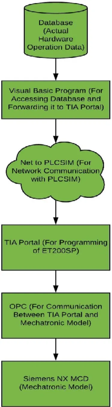
The aim of the thesis is to develop a methodology for validating the mechatronic digital twin. The proposed methodology can be used with the mechatronic models of existing systems to assure the proper operation of the actual system. It enables the user to observe and detect the problems, by replaying the recorded process data of actual hardware operation and movements in the mechatronic model, which can assist the user to point out the problem. A number of steps were adopted to implement the desired system as described in figure 14. The research approach is briefly described in the text below.
Defining requirements and goals: Identifying the problem and setting the goals is the most crucial part of any research. A thorough analysis and effort is required to study the root cause of the problem. After the problem definition, there is need for some objectives which are stated in the introduction section of this thesis. On the basis of the goal defined at this stage, a work plan was made in order to achieve an efficient solution. In this step, the aim of the thesis was decided, which suggested that a methodology should be developed so a mechatronic digital twin could be validated and verified.
Theoretical Background: An efficient and reliable solution requires the literature review based on the problems defined in the introduction section. For getting the overall idea and knowledge of the existing technologies, literature review was done with the help of articles, books, conference proceedings and other reliable online resources. It gave the understanding of the work previously done by other researchers and their results so the same mistakes can be avoided while the designing and implementation phase of the desired system.
Keeping the aim in mind which was defined in the requirements of the thesis, research was conducted using the above-mentioned sources. In this phase, different technological decisions were made based on the outlined goals. First decision was the selection between Inico S1000 controller and Siemens ET200SP Controller. ET200SP controller was preferred as it is one of the latest technologies by Siemens for process control and also because Siemens NX was selected for the designing of mechatronic model of the said system and initially the assumption was that it will be comparatively easy to integrate these tools as both are offered by Siemens.
One example of compatibility between these tools is the possibility of detection of the PLCSIM Advanced in the Siemens NX, which is an extra channel for communication with mechatronic model offered by Siemens. However, third-party software was used as data logging of the process parameters of actual operation is required, which is necessary for the validation of the mechatronic model.
Designing: Literature review helped in understanding the existing systems and provided a necessary understanding of the concepts related to it. Tools were selected in this phase based on the information gathered in the theoretical background. Software and hardware components were also finalized in this phase to proceed further. As Festo MPS 500 system is used in the implementation so both stations of the Festo system were studied thoroughly to understand the process. Initial testing was performed considering a simple system with the selected tools in the literature review phase and communication was established for the purpose of exchanging the information between these softwares.
Implementation: After the selection of the tools and initial testing in the designing phase, the next step was to move towards the implementation of the actual system instead of working with the example system. In this phase, mechatronic model of the testing and distribution stations are made in the selected software. Communication established in the designing phase is used for data exchange between the control program and mechatronic model. After the integration of database, it was successful completion of the implementation phase.
Verify: As a next step after completing the implementation of the system under consideration, verification was done. Various test were performed for the purpose of analyzing the system and its capabilities. In the test sessions, the data of the actual operation which was initially stored in the database was sent to the mechatronic model of the distribution and testing stations. At this stage, the outcome was compared with the goals defined in the first phase. If there were problems which are not expected then changes were made in the implementation section to achieve the desired results. Documentation: When a working solution was developed as defined in the initial stages of the thesis, documentation was done. In the documentation, detail about development stages, engineering tools and integration technologies were included that can help the researchers in the future. It also contains the outcome of the thesis work for future reference.
4. IMPLEMENTATION
This chapter provides the detail about the hardware and software used for the implemen-tation purpose of a mechatronic digital twin of distribution and testing simplemen-tations of Festo MPS 500 System. It gives a brief idea about the link that was established for the data exchange between various engineering tools, using OPC. Different programming lan-guages for the control logic are also discussed along with establishing communication between two controlling modules.
4.1 System Architecture
This section provides detail about the whole system architecture. It is to introduce engineering tools and technologies that are used in the implementation of the whole setup. The thesis was divided into two phases to get a clear picture of the work being done. The first phase was to study about selected stations of Festo MPS 500 system. Making a control program and verifying it was also a part of it. Additionally, the link for storing the process parameters in the database was also established, which was needed in the later stages of the implementation. Figure 15 shows the architecture of the first phase of the implemented system.
The second phase of the thesis was to fetch the process parameters data stored in the database and passing that data to the controllers as shown in figure 16. Microsoft Access database is used in this thesis. Data of the process signals were stored with timestamps so that the exact movements of the system could be seen in Siemens NX. In visual basic, S7.net library was used for the connection with the ET200SP’s of distribution and testing
stations. After the successful connection with the TIA Portal, OPC was used for data exchange between control program of both stations and mechatronic model. The communication link between all these tools was established successfully and system was implemented as defined in the initial stages.
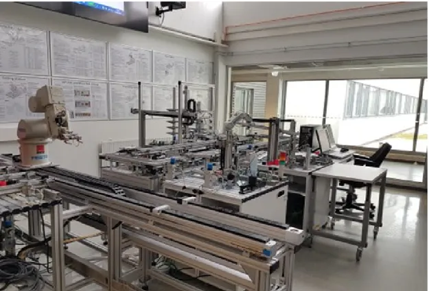
4.2 Hardware
In Fast lab of the Tampere University of Technology, Festo MPS 500 System has been installed as shown in figure 17. It consists of various stations, which have different sensors, actuators, light barriers, valves and switches. All of these stations are connected with their respective ET200SP, for the control purpose. More detailed review about hardware is provided in the subsections below that was used for the implementation purpose of this thesis.
4.2.1 Festo MPS 500 System
Each station in the Festo line is the whole world in itself. Festo is one of the leading companies in the automation world, especially in the mechatronics field. Festo MPS 500 is widely used all over the world for industrial vocational training by which programmers can get the experience of working with the whole system and synchronizing it.
Figure 17 FESTO MPS 500 System- FAST Lab
Distribution station is mainly for separating the workpieces from the stack magazine module. Magazine tube of the stack has the space of storing up to 8 pieces. The light barrier is also present in the stack magazine for the detection of the workpiece. A double
acting cylinder, which is right beneath the stack module, can push out the workpieces individually.
There is also pneumatic swivel arm installed on the distribution station for transferring the workpiece from distribution station to the next station as shown in figure 18. Swivel arm is further attached with vacuum gripper, which can hold the workpieces during the transfer from one station to another. A vacuum switch is also integrated with the vacuum gripper so the user could know if the workpiece has been picked up.
There are limit switches installed to track the movement of the cylinder, installed beneath the stack module. It helps to know that if the cylinder is in a retracted position or extracted position. Same is the case with swivel arm, to get the information that if the swivel arm is in the distribution station or the next station. These limit switches are very important for the safety of the swivel arm.
In the lab, adjacent to the distribution station, the testing station is installed. Testing station is capable of differentiating between the workpieces, inserted by the swivel arm of distribution station. A capacitive sensor is present in the station for sensing the availability of the workpiece. Next to the capacitive sensor, the diffuse sensor is present
for sensing the color of the inserted workpiece. It is calibrated in such a way that it gives false bit value for red workpieces and true bit value for silver workpieces.
Figure 19 Testing Station
Moreover, as shown in figure 19, a lifting module is also present in the testing station. It carries the workpiece towards the upper position. A sensor of a measuring module is installed on the top position of the lifting module. It can sort out the pieces on the basis of their heights as in the lab there are workpieces present with heights different from each other. When workpieces touch this height sensing part, a bit turns true otherwise it stays false.
There are limit switches installed with the lifting module to know that if it is in the upper position or on its normal (downward) position. A through-beam sensor monitors whether the workspace above the lifter module is empty or not as the swivel arm of the distribution station can reach this space and can cause damage to itself and the lifter module. There are two air cushion slides also integrated with the system. According to the control program and the sorting method used for the workpieces, upper air cushion slide and lower air cushion slide can be used.
4.2.2 ET200SP Control Unit
ET200SP is a distributed Input-output control system, which is highly flexible and scalable. It is capable of connecting the integrated process signals to central control station using Profinet. According to Siemens, it is very easy to operate for the user as it has the room for the connection of Profinet technology by using a bus adapter. There is push-in technology used with modules, which enables the user to do wiring without using traditional tools. It is also integrated with channel-specific diagnostic functions.
Figure 20 ET200SP Module- Distribution Station
It is very compact in design and can be fitted in standard control boxes of dimension 80mm. It means a lot of space can be saved for other modules and less complexity. It also has the option of expandability up to 64 modules, which is really useful for setting up a process with a lot of process and control signals.
Fast data exchange is also possible using ET200SP when used with Profinet. Additionally, its configuration can be changed using the software e.g. TIA Portal, Step 7.
There is also a concept of ”Hot-Swapping”, which is applicable in this control unit. It
means that signal modules and terminal boxes can be changed even if the system is running. It is very beneficial for troubleshooting scenarios [57]. Further ET200SP also has various connection technologies for Profinet, by using bus adapters. In figure 20, The first module is BA 2xRJ45 for the connection with RJ45 plugs. The second module is the Central Processing Unit (CPU) of ET200SP, capable of controlling the signal
modules. With Profinet connection, it behaves the same as CPU 1511/ CPU 1513 of the 1500 controller [58]. It is commonly used as Remote terminal Unit (RTU) with S7-1500 in the industries. However, it can be used as an independent module as installed with the stations of Festo MPS 500 system in Fast lab.
Next to the CPU module of ET200SP, there are signal modules attached to the rail. In this case, there are three digital input signal modules and two digital output modules. One CPU module of ET200SP can support up to 64 input and output modules. One signal module has seven digital inputs or digital outputs so it is capable of reading real-time values of seven sensors or giving output to seven motors or actuators. The fail-safe function is also integrated with these signal modules for the safety of the user and the hardware. The same setup as shown in figure 20 is used for controlling purpose of the testing station, with the same number of signal modules and bus adapter.
4.3 Software
This section briefly describes the software modules used for the implementation purpose of this thesis. The implementation is not possible without the establishment of communication between these engineering tools (e.g. Siemens TIA Portal, Siemens NX MCD). These tools are discussed in the subsections below.
4.3.1 Mechatronics Concept Designer (MCD)
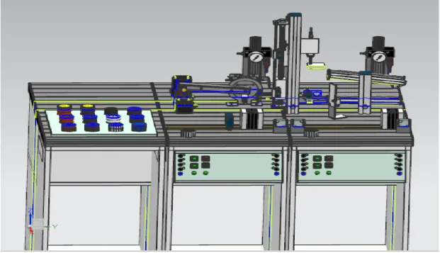
Mechatronics concept designer is an add-on offered by Siemens in Siemens NX software. In the MCD, it is possible to make the 3D model of any machine or station under consideration, following the desired requirements. Along with 3D design, It enables the user to make the kinematic simulation of the desired model. For the kinematic simulation, 3D model is needed to be converted to a mechatronic model by connecting the appropriate sensors, actuators or cylinders. These automation tools can help the design to sense the environment around. MCD is used in the early stages of development of a prototype because it enables the user to test alternative paths for achieving the desired actions. With more than one options, it is comparatively easy to select an efficient and reliable design.
In this thesis, 3D models of the distribution and testing stations have been converted to mechatronic model using mechatronics concept designer. 3D models of both stations are imported from the Ciros Studio. Siemens NX can import the models from a number of formats like CGM, Part, AutoCAD DXF/ DWG, Parasolid, VRML etc. From Ciros Studio VRML file type was imported to Siemens NX MCD.
![Figure 1 Industrial revolution [10]](https://thumb-us.123doks.com/thumbv2/123dok_us/1992708.2796058/11.892.195.750.154.597/figure-industrial-revolution.webp)
![Figure 4 Software in the loop [21]](https://thumb-us.123doks.com/thumbv2/123dok_us/1992708.2796058/20.892.191.817.142.817/figure-software-in-the-loop.webp)
![Figure 5 Hardware in the loop [21]](https://thumb-us.123doks.com/thumbv2/123dok_us/1992708.2796058/21.892.182.811.215.798/figure-hardware-in-the-loop.webp)
![Figure 6 Kuka Robot Simulation [51]](https://thumb-us.123doks.com/thumbv2/123dok_us/1992708.2796058/23.892.314.662.110.423/figure-kuka-robot-simulation.webp)
![Figure 8 Robot based Processing Station Factory I/O [49]](https://thumb-us.123doks.com/thumbv2/123dok_us/1992708.2796058/24.892.177.802.304.665/figure-robot-based-processing-station-factory-i-o.webp)
![Figure 10 Visual Components Robotic Simulation [56]](https://thumb-us.123doks.com/thumbv2/123dok_us/1992708.2796058/26.892.179.801.211.565/figure-visual-components-robotic-simulation.webp)