Abstract— This paper is focused on multi-objective design of
multi-machine power system stabilizers (PSSs) using Modified Shuffled Frog Leaping Algorithm (MSFLA). The effectiveness of the proposed scheme for optimal setting of the widely used CPSSs has been attended. The PSSs parameters designing problem is converted to an optimization problem with the multi-objective function including the desired damping factor and the desired damping ratio of the power system modes which are solved by a MSFL algorithm. The capability of the proposed approach is confirmed on three power systems called Single Machine Infinite Bus (SMIB), four-machine of Kundur and ten-machine New England systems under different operating conditions and disturbances. The results of the proposed approach are compared with the genetic algorithm (GA) based tuned PSS through some performance indices to reveal its strong performance.
Index Terms— Multi-objective optimization, Genetic Algorithm (GA), Modified Shuffled Frog Leaping Algorithm (MSFLA), PSS design
I. INTRODUCTION
One of the most important aspects in electric system operation is the stability of power systems. This issue form from the fact that the power system must maintain frequency and voltage levels, under any disturbance, like a sudden increase in the load, loss of one generator or switching out of a transmission line during a fault [1]. Power systems face low frequency oscillations (in order of 0.1-2.5 Hz) during and after a large or small disturbance has happened to a system, especially for middle to heavy loading conditions [2, 3]. These oscillations may sustain and grow to cause system separation if there is not an adequate damping [4]. PSSs are the most effective devises for damping low frequency oscillations and increasing the stability of the power systems [5]. A PSS provides additional feedback stabilizing signals in the excitation system. In spite of the capability of modern control techniques with different structures, power system utilities still prefer the conventional power system stabilizer (CPSS) structure [6,7]. CPSSs still are widely being used in the power systems and this may be because of some difficulties behind the using new methods.
New intelligent control design methods such as fuzzy logic controllers [8,9] and artificial neural network controllers [10] have been used as PSSs. Recently, intelligent optimization
Manuscript received July, 2014.
Majid Alizadeh Moghadam, Electrical Engineering Department, University of Ghiaseddin Jamshid Kashani, Abyek, Iran.
methods like genetic algorithms (GA) [11–14], simulated annealing [15], evolutionary programming [16] and rule based bacteria foraging [17] have been applied for PSS parameter optimization. These evolutionary algorithms are heuristic population-based search procedures that incorporate random variation and selection operators. Even though, these methods seem to be good methods for the solution of PSS parameter optimization problem However, when the system has a highly epistatic objective function (i.e. where parameters being optimized are highly correlated), and number of parameters to be optimized is large, then they have degraded efficiency to obtain global optimum solution and also simulation process use a lot of computing time. Moreover, in [11, 12] and [15, 16] the robust PSS design was formulated as a single objective function problem, and not all PSS parameter were considered adjustable. In order to dominate these disadvantages, the Modified Shuffled Frog Leaping Algorithm (MSFLA) based PSS (MSFLAPSS) is proposed in this paper. The MSFL technique is used for optimal tuning of PSS parameter to improve optimization synthesis and the speed of algorithm convergence.
In this paper, the problem of PSS design is formulated as a multi-objective optimization problem and MSFLA is used to solve this problem. The PSSs parameters designing problem is converted to an optimization problem with the multi-objective function including the desired damping factor and the desired damping ratio of the power system modes. The capability of the proposed MSFLA is tested on three power systems called Single Machine Infinite Bus (SMIB), four-machine of Kundur and ten-machine New England systems under different operating conditions in comparison with the GA based tuned PSS (GAPSS) through some performance indices. Results show that the proposed method achieves stronger performance for damping low frequency oscillations under different operating conditions than other methods and is superior to them.
II. DESIGN OF OBJECT FUNCTION
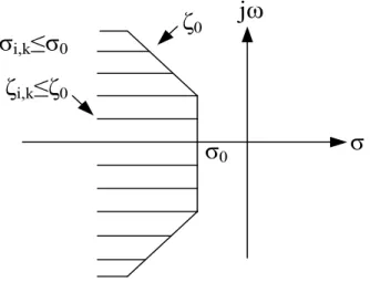
For this purpose, a multi-objective function comprising the damping factor and the damping ratio is considered as follows [14, 18]: 2 1 , 0 2 1 0 , 0 0 , , ] [ ] [
p j i p j i n j j i n j j i a J (1)Multi-machine System by Using MSFLA
Majid Alizadeh Moghadam
This method’s performance is shown in figure 1.
σ
i,k≤σ
0ζ
i,k≤ζ
0σ
0ζ
0jω
σ
Figure 1. Objective performance
Different inequalities have been proposed to be satisfied [14]: 1)k madr. k(1,2,...ngen1)
2)
(
1
min)
k
k
Im(
k)
(
1
max)
k Where is defined according to system specifications. 3)i mmdr. The performance of this technique has been shown in figure 2.In order to use advantages of the above mentioned references, objectives are considered as follow:
))) ( ( ( :y1 Minabs k Minimize
(2) )) ( ( :y2 Min k Minimize (3)Im
Re
mmdrζ
=
ζ
madrζ
=
ζ
λ
k1
+γ
maxω
k1-γ
minω
k Electromechaniacl Modes Damping Region Non-dominant Modes Damping RegionFigure 2. Objective performance
Subject to:
1)i 0, for all eigenvalues. This condition guarantees system small signal stability.
2) Forthe electro-mechanical modes:akb
3) For all other modes:i mmdr
The value of mmdr for different systems is shown in table I. TABLE I. THE CAPTION MUST BE FOLLOWED BY THE TABLE Parameter
s
SMIB TAFM New England
ζmmdr 0.2 0.2 0.1
For the CPSS, the vector of parameters ids defined as follow:
) , , , , , (T1 T2 T3 T4 VSmax kPSS x
The CPSS parameters bounds are shown in table II.
TABLE II. THE CAPTION MUST BE FOLLOWED BY THE TABLE Parameter s T1 T2 T3 T4 VSmax KPSS Maximum 1 1 10 10 0.5 100 Minimum 0.01 0.0 1 0.0 1 0.0 1 0.05 10
The main object here is to minimize the following objective function:
1
1 1 2 2
( )
OF r y r y (5)
Wherey and1 y are objective functions. In order to have 2
comprehensive investigation, different values for weights,
1
r
andr
2are assumed.III. HEURISTIC OPTIMIZATION METHOD A. Modified Shuffled Frog Leaping Algorithm
In the natural memetic evolution of a frog population, the ideas of the worse frogs are influenced by the ideas of the better frogs, and the worse frogs tend to jump toward the better ones for the possibility of having more foods. The frog leaping rule in the shuffled frog leaping algorithm (SFLA) is inspired from this social imitation, but it performs only the jump of the worst frog toward the best one [2]. According to the original frog leaping rule presented above, the possible new position of the worst frog is restricted in the line segment between its current position and the best frog’s position, and the worst frog will never jump over the best one (figure 3). Clearly, this frog leaping rule limits the local search space in each memetic evolution step.
D
X
WX
b
X
W(new)
Figure 3. The original frog leaping rule
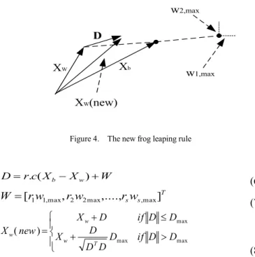
This limitation might not only slow down the convergence speed, but also cause premature convergence. In nature, because of imperfect perception, the worst frog cannot locate exactly the best frog’s position, and because of inexact action, the worst frog cannot jump right to its target position. Considering these uncertainties, we argue that the worst frog’s new position is not necessary restricted in the line connecting its current position and the best frog’s position. Furthermore, the worst frog could jump over the best one. This idea leads to a new frog leaping rule that extends the local search space as illustrated in figure 4 (for 2-dimensional problems). The new frog leaping rule is expressed as:
D
XW Xb
XW(new)
w2,max
w1,max
Figure 4. The new frog leaping rule
W X X c r D . ( b w) (6) T s sw r w r w r
W [1 1,max, 2 2max,...., ,max]
(7) max max max ) ( D D if D D D D X D D if D X new X T w w w (8) where r is a random number between 0 and 1; c is a constant chosen in the range between 1 and 2; ri (1<i<S) are random numbers between -1 and 1; wi,max (1<i<S) are the maximum allowed perception and action uncertainties in the ith dimension of the search space; and Dmax is the maximum allowed distance of one jump. The flow chart of the local memetic evolution using the proposed frog leaping rule is illustrated in figure 5.
The new frog leaping rule extends the local search space in each memetic evolution step; as a result it might improve the algorithm in term of convergence rate and solution
performance provided that the vector Wmax=[w1,max,…, wS,max]T is appropriately chosen. However, if ||Wmax|| is too large, the frog leaping rule will loss its directional characteristic, and the algorithm will becomes more or less random search. Therefore, choosing a proper maximum uncertainty vector is an issue to be considered for each particular optimization problem.
Start First Memeplex: i=1
First Iteration: j=1
Determine Xg, Xb and Xw Apply Equations (6), (7) and (8)
Apply Equations (1), (2) and (3) with Replacing Xb by Xg
Replace the Wost Frog Xw Next Jump :j=j+1 Done Is Xw(new) Better than Xw? Is Xw(new) Better than Xw?
Generate a New Frog Randomly
j < Jmax ?
Next Memeplex: i=i+1
i < m ? Yes Yes No No Yes Yes No No
Figure 5. The MSFLA flowchart
B. Genetic Algorithm
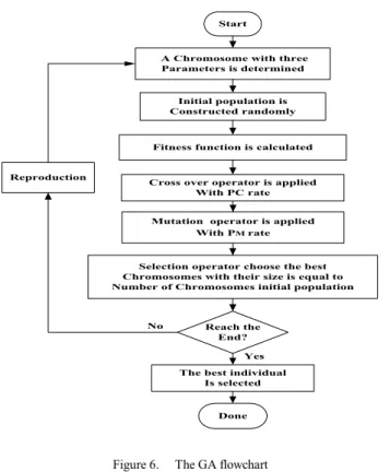
It is well known that GAs work according to the mechanism of natural selection stronger individuals are likely to be the winners in a competitive environment. In practical applications, each individual is codified into a chromosome consisting of genes, each representing a characteristic of one individual. For identification of the unknown parameters of a model, parameters are regarded as the genes of a chromosome, and a positive value, generally known as the fitness value, is used to reflect the degree of goodness of the chromosome. Typically, a chromosome is structured by a string of values in binary form, which the mutation operator can operate on any one of the bits, and the crossover operator can operate on any boundary of each two bits in
the string [19, 20]. Since in our problem the parameters are real numbers, a real coded GA is used, in which the chromosome is defined as an array of real numbers with the mutation and crossover operators. Here, the mutation can change the value of a real number randomly, and the crossover can take place only at the boundary of two real numbers. More details of proposed GA are shown in figure 6.
Start
A Chromosome with three Parameters is determined
Initial population is Constructed randomly
Fitness function is calculated
Cross over operator is applied With PC rate Mutation operator is applied
With PM rate
Selection operator choose the best Chromosomes with their size is equal to Number of Chromosomes initial population Reproduction
The best individual Is selected Done Reach the End? Yes No
Figure 6. The GA flowchart
IV. CASE STUDY
A. Single Machine Infinite Bus (SMIB) System
In order to evaluate the proposed method, a single machine infinite bus (SMIB) model of a power system is assumed initially. In this model, a typical 500MVA, 13.8 kV, 50Hz synchronous generator is connected to an infinite bus through a 500MVA, 13.8/400KV transformer and 400KV, 350 Km transmission line [21]. This system has been shown in figure 7.
Infinite Bus
350KmFigure 7. Single Machine Infinite Bus (SMIB) system
B. Four Machine system
PSS design for a multi-machine system with a strong inter-area mode has received extensive attention from the researchers and designers. In this paper, the Kundur’s
Four-Machine (TAFM) system consisting of two fully symmetrical areas linked together by two 220Km, 230KV transmission lines is used as the multi-machine system [22]. Generally, in order to study the low frequency electromechanical oscillations, this power system is used. This system has been shown in figure 8.
G3 G4 G2 G1 Load A Load B 1 2
Figure 8. Four-Machine (TAFM) system
G2 G3 G5 G7 G8 G1 G10 G9 G6 G4 29
Figure 9. New England power system
C. Ten-Machine System
The last PSS design process is applied to New England power system consisting of 10 machines and 39 buses as shown in figure 9. All generators except G10 are equipped with CPSS [23].
D. PSS Structure
The model of the CPSS is illustrated in figure10. This model consists of two phase-lead compensation blocks, a gain block and a signal washout block. The value of TW is usually not critical and it can range from 0.5 to 20 s. In this paper, it is fixed to 10 s. the six other constant coefficients of the model ( T ,1 T ,2 T3 , T ,4 VSmax and KPSS ) should be designed properly.
sTw
1+sTw Kpss
(1+sT1)(1+sT3)
(1+sT2)(1+sT4) Δω
Figure 10. Power system stabilizer V. SIMULATION AND RESULT
The proposed MSFLA methodology and GA are programmed in MATLAB running on an Intel w Core TM2 Duo Processor T5300 (1.73 GHz) PC with 1 GB RAM. It is applied on SIMB, TAFM and New England systems to demonstrate its abilities. The effect of MSFLA parameters on average fitness function (among 100 trials) is investigated. The colony size (NC) tried was 100. Hundred independent trials have been made with 100 iterations per trial. The performance of the MSFLA also depends on the number of colonies. The parameters of MSFLA are selected based on the average fitness function. After a number of careful experimentation, following optimum values of MSFLA parameters have finally been settled: NC = 100; Dmax = 0.7, ri= 1; C=1.3; r=0.6.
A. SMIB System
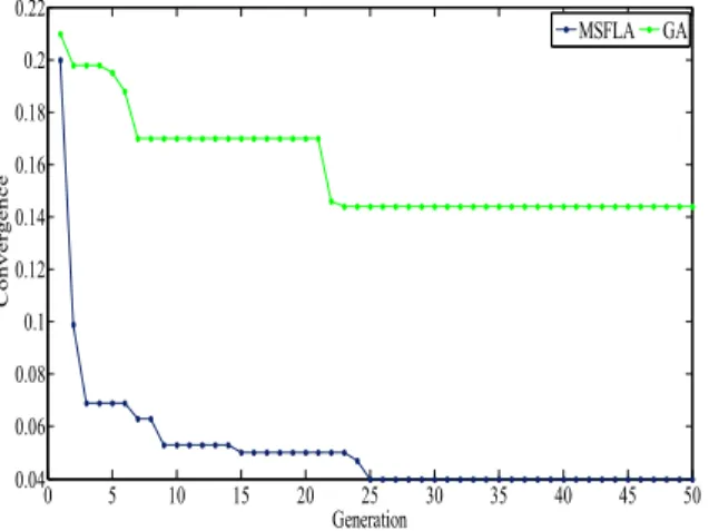
At first the design process is applied to design a PSS for a SMIB system. The minimum fitness value evaluating process is shown in figure11. 0 5 10 15 20 25 30 35 40 45 50 0.04 0.06 0.08 0.1 0.12 0.14 0.16 0.18 0.2 0.22 Generation Co n v e rg e n c e MSFLA GA
Figure 11. Variations of objective function for SMIB system
TABLE III. OPTIMAL PSSS PARAMETERS USING MSFLA AND GA SCHEMES FOR SMIB SYSTEM
Method
T1 T2 T3 T4 V
smax KPSS
GA 0.8 0.5 1.3 6.4 0.34 33.2
MASLA 0.6 0.1 1 7 0.3 21.4
The MSFLA algorithm is run several times and then optimal set of PSS parameters is selected. The set value of PSSs' parameters using both the proposed MSFLA and GA are given in table III.
To have a better understanding, dominant oscillatory poles’ maps of the system, comprising some optimum PSSs are shown in figure 12. As it obvious from the figure, the open-loop system is unstable.
TABLE IV. OPTIMAL PSSS PARAMETERS USING MSFLA AND GA SCHEMES FOR SMIB SYSTEM
Method G1 G4 GA T1 0.36 0.84 T2 0.04 0.3 T3 1.6 2.3 T4 7.1 8.3 Vsmax 0.3 0.28 Kpss 68 12.9 MSFLA T1 0.73 1 T2 0.11 0.06 T3 1.78 3 T4 6.7 5 Vsmax 0.2 0.03 Kpss 36.8 45 -4 -3 -2 -1 0 1 -15 -10 -5 0 5 10 15 =3 =2 =0.2 OL GA MSFLA
Figure 12. Dominant modes of SMIB system
B. TAFM System
The other system employed to evaluate the proposed method is the Four-Machine (TAFM) (figure 6). Two PSSs with similar settings are installed at G1 and G4. Figure13 shows the minimum fitness value evaluating process.
0 5 10 15 20 25 30 35 40 45 50 0.04 0.06 0.08 0.1 0.12 0.14 0.16 0.18 0.2 Generation Co n v e rg e n c e MSFLA GA
Figure 13. Variations of objective function for TAFM system
To have a better understanding, dominant oscillatory poles’ maps of the system, comprising some optimum PSSs are shown in figure 14. It can be understand from the figure that the electro-mechanical modes are close together, but
there is a higher difference in the other oscillatory mode of some PSSs. In addition, instability of the open-loop system is clear. The designed PSSs’ characteristics are presented in table IV.
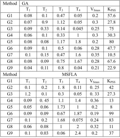
TABLE V. OPTIMAL PSSS PARAMETERS USING MSFLA AND GA SCHEMES FOR TAFM SYSTEM
Method GA T1 T2 T3 T4 VSmax KPSS G1 0.08 0.1 0.47 0.05 0.2 57.6 G2 0.07 0.9 1.12 0.05 0.3 27.8 G3 0.09 0.33 0.14 0.045 0.25 75 G4 0.06 0.1 0.33 1 0.3 30.3 G5 0.08 0.08 1.17 1.8 0.2 80 G6 0.09 0.1 0.5 0.06 0.28 47.7 G7 0.1 0.15 0.47 1.6 0.35 10.5 G8 0.08 0.09 0.75 1.67 0.28 67.6 G9 0.04 0.11 0.8 0.04 0.21 22.9 Method MSFLA G1 T1 T2 T3 T4 VSmax KPSS G2 0.1 0.2 1. 8 0.11 0. 25 42 G3 1.2 0.1 0.3 0.05 0. 33 27.3 G4 0.09 0. 45 1.1 1.4 0.36 13 G5 0.05 0.06 1.73 1 0.2 8 G6 0.09 0.09 0.67 1.87 0.19 99 G7 0.1 0.2 1.68 0.075 0.24 83 G8 0.06 0.08 1 2 0.32 11 G9 0.1 0.03 0.06 2.4 0.2 37
C. New England System
One of most important issues in PSS design process is to test proposed method in a large system. Hence, in order to reveal its robust performance, the proposed technique, is applied to New England system. The convergence value of MSFLA and GA is presented in figure 15, introducing acceptable improvement through generation increment. The system’s dominant oscillatory poles’ map with candidate MSFLA and GA based PSSs is drawn in figure 16. The parameters’ numerical values of both algorithms are given in table V. The comparative evaluation from test results shows its robust performance. -3 -2.5 -2 -1.5 -1 -0.5 0 0.5 1 -8 -6 -4 -2 0 2 4 6 8 10 = =0.2 =2 GA OL MSFLA
Figure 14. Dominant modes of TAFM system
0 5 10 15 20 25 30 35 40 45 50 0 0.5 1 1.5 2 2.5 3 Generation Co n v e rg e n c e MSFLA GA
-6 -5 -4 -3 -2 -1 0 1 2 -20 -15 -10 -5 0 5 10 15 20 =0.1 =3 = GA MSFLA OL
Figure 16. Dominant modes of New England system
A comparison among the results of the proposed algorithm MSFLA and GA presents in table 6. Comparison the proposed optimization algorithm (MSFLA) with those of the other methods confirms the effectiveness of the proposed method. Table 5 provides the average value (AFF) of the objective function, based on the proposed method and the other one. This would show the convergence characteristics of the proposed MSFLA compared with other method. The average value of objective function in the proposed MSFLA method is less than GA. This means that the MSFLA is more robust compared to GA. Execution time (MT) complexity of each optimization method is very important for its application to real systems. The execution time of the proposed MSFLA compared with other methods is given in the last row of table VI. One of the main advantages of the proposed method is that the convergence of MSFLA algorithm is faster and less time consuming (see table 6) as compared to the other applied methods. Because the proposed algorithm (MSFLA) provides the correct answers with high accuracy in the initial iterations which make the responding time of this algorithm extremely low.
TABLE VI. COMPUTATIONAL PERFORMANCE COMPARISON BETWEEN MSFLA AND GA METHODS
System GA MSFLA
AFF MT(Sec) AFF MT(Sec)
SMIB 0.056 4854 0.0514 3647
TAFM 0.094 12216 0.08 10816
New England 0.4263 31943 0.2126 27214
D. Nonlinear Time Domain Simulation
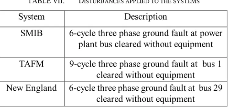
To evaluate the performance of the MSFLA based tuned PSSs under fault conditions, some large disturbances have been applied to the systems. Descriptions of three different faults
applied to evaluate the robustness of PSSs are represented in table VII.
TABLE VII. DISTURBANCES APPLIED TO THE SYSTEMS
System Description
SMIB 6-cycle three phase ground fault at power plant bus cleared without equipment TAFM 9-cycle three phase ground fault at bus 1
cleared without equipment New England 6-cycle three phase ground fault at bus 29
cleared without equipment
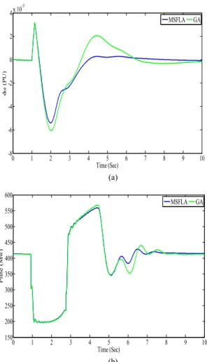
Rotor speed deviation of a generator located close to the fault position and variations of active power of a selected line are plotted against time for various PSSs and the faulty operating condition as shown in figures 17 - 19.
As it can be seen from figures, the MSFLA based tuned PSSs achieves good robust performance and provides superior damping in comparison with the other methods. It can be concluded that the proposed MSFLAPSSs provides much proper control signals than the GAPSSs and CPSSs.
0 1 2 3 4 5 6 7 -0.02 -0.015 -0.01 -0.005 0 0.005 0.01 0.015 Time (Sec) d (P U ) MSFLA GA None (a) 0 1 2 3 4 5 6 7 -200 0 200 400 600 800 1000 Time (Sec) P li n e (M w ) MSFLA GA None (b)
0 1 2 3 4 5 6 7 8 9 10 -8 -6 -4 -2 0 2 4x 10⁻³ Time (Sec) d (P U ) MSFLA GA (a) 0 1 2 3 4 5 6 7 8 9 10 150 200 250 300 350 400 450 500 550 600 Time (Sec) P li n e (M w ) MSFLA GA (b)
Figure 18. TAFM: a- Rotor speed deviation; b- Active power
0 1 2 3 4 5 6 7 -0.01 -0.005 0 0.005 0.01 0.015 Time (Sec) d (P U ) MSFLA GA (a) 0 1 2 3 4 5 6 7 -200 0 200 400 600 800 1000 Time (Sec) P L in e (M w ) MSFLA GA (b)
Figure 19. New England: a- Rotor speed deviation; b- Active power VI. CONCLUSION
The power system must maintain frequency and voltage levels, under any disturbance and oscillation. In such a case PSS is the most effective devices for damping low frequency oscillations and increasing the stability of the power systems. Therefore, this paper presents a multi-objective design of multi-machine power systems stabilizers (PSSs) using Modified Shuffled Frog Leaping Algorithm (MSFLA). The stabilizers are optimally tuned with optimization a multi-objective function including the damping factor, and the damping ratio of the power system modes. The proposed MSFLA algorithm for tuning PSSs is easy to implement without additional computational complexity. The effectiveness of the proposed approach is confirmed on three power systems, Single Machine Infinite Bus (SMIB), four-machine of Kundur and New England systems under different operating conditions and disturbances. The ability of proposed scheme Compared with GA can be summarized as follow:
Damping out local as well as inter area modes of oscillations.
The faster convergence and less time consuming The less fitness function which shows its robust
preference than other method
The ability to jump out the local optima
Providing the correct answers with high accuracy in the initial iterations
Superiority in computational simplicity, success rate and solution quality
Units
np The number of operating points
σi,j The real part of the ith eigenvalue of the jth operating point
ξi,j The damping ratio of the ith eigenvalue of the jth operating point
ξmadr The minimum acceptable damping ratio
ωk The frequency of kth mode
ξmmdr The minimum marginal damping ratio
σk The real part of the kth electromechanical modes
ξk The damping ratio of the kth
electromechanical modes
a The empirically considered limits of
frequency
b The empirically considered limits of
frequency
OF Objective function
REFERENCES
[1] Hugang X, Haozhong Ch, Haiyu L, Optimal reactive power flow incorporating bstatic voltage stability based on multi-objective adaptive immune algorithm, Energy Conversion Magazine, vol. 49, pp. 1175 – 1181, August. 2008.
[2] Saeid Jalilzadeh, Reza Noroozian, Mahdi Sabouri, Saeid Behzadpoor, PSS and SVC Controller Design Using Chaos, PSO and SFL Algorithms to Enhancing the Power System Stability, Energy and Power Engineering, vol. 49, pp. 87-95, August. 2011.
[3] S. Sheetekela, K. Folly and O. Malik, Design and Implementation of Power System Stabilizers based on Evolutionary Algorithms, IEEE AFRICON, pp.23-25, September. 2009.
[4] M. A. Abido and Y. L. Abdel-Magid, Coordinated De-sign of a PSS and an SVC-Based Controller to Enhance Power System Stability, International Journal of Electrical Power and Energy Systems, vol. 25, n. 9, pp. 695-704, 2003.
[5] P.M. Anderson, A.A. Fouad, Power System Control and Stability, lows State University Press, lows, USA, 1997.
[6] Larsen E, Swann D, Applying power system stabilizers, IEEE Trans Power Appl Syst, vol. 100, pp. 3017–46, 1981.
[7] Tse GT, Tso SK, Refinement of conventional PSS design in multimachine system by modal analysis, IEEE Trans Power Syst, vol. 8, pp. 598–605, 1993.
[8] Fraile-Ardanuy J, Zufiria PJ, Design and comparison of adaptive power system stabilizers based on neural fuzzy networks and genetic algorithms, Neurocomputing, vol. 70, pp. 2902–2912, 2007.
[9] Barto Z, Robust control in a multimachine power system using adaptive neuro-fuzzy stabilizers, IEE Proc Gener Transm Distrib, vol.151, no.2, pp. 261–267, 2004.
[10] Segal R, Sharma A, Kothari ML, A self-tuning power system stabilizer based on artificial neural network, Electr Power Energy Syst, vol. 26, pp.423–430, 2004.
[11] Abdel-Magid YL, Abido MA, AI-Baiyat S, Mantawy AH, Simultaneous stabilization of multimachine power systems via genetic algorithms, IEEE Trans Power Syst, vol. 14, no. 4, pp.1428–1439, 1999.
[12] Abido MA, Abdel-Magid YL, Hybridizing rule-based power system stabilizers with genetic algorithms, IEEE Trans Power Syst, vol. 14 no. 2, pp.600–607, 1999.
[13] Zhang P, Coonick AH, Coordinated synthesis of PSS parameters in multi-machine power systems using the method of inequalities applied to
genetic algorithms, IEEE Trans Power Syst, vol. 15 no. 2, pp.811–816, 2000.
[14] Abdel-Magid YL, Abido MA, Optimal multiobjective design of robust power system stabilizers using genetic algorithms, IEEE Trans Power Syst, vol. 18 no. 3, pp.1125–1132, 2003.
[15] V. Abdel-Magid YL, Abido MA, Mantawy AH, Robust tuning of power system stabilizers in multimachine power systems, IEEE Trans Power Sys, vol. 15 no. 2, pp.735–740, 2000.
[16] Abido MA, Robust design of multimachine power system stabilizers using simulated annealing, IEEE Trans Energy Convers, vol. 15 no. 3, pp.297–304, 2003.
[17] Abdel-Magid YL, Abido MA, Mantawy AH, Robust tuning of power system stabilizers in multimachine power systems, IEEE Trans Power Sys, vol. 15 n. 2, pp.735–740, 2000.
[18] P. Zhang and A. H. Coonick, Coordinated synthesis of PSS parameters in multi-machine power systems using the method of inequalities applied to genetic algorithms, IEEE Trans. Power Systems, vol. 15, pp. 811-816, 2000.
[19] Raie, and V. Rashtchi, Using genetic algorithm for detection and magnitude determination of turn faults in induction motor, Electrical Engineering, vol. 84 n. 3, pp. 275 – 279, August. 2002.
[20] S. jalilzadeh, M. azari, A Novel Approach for PID Designing for Load Frequency Control System, International Review on Modeling and Simulation (I.RE.MO.S), ), vol. 5 n. 3, pp. 1159 –1164, June. 2012. [21] M. Kashki, A. Gharaveisi, F. Kharaman, Application of CDCARLA
technique in designing Takagi-Sugeno fuzzy logic power system stabilizer, IEEE Power and Energy Conference (PECON), pp.280-285, 2006. [22] P. Kundur, Power System Stability and Control, New York: McGraw-Hill,
1994.
[23] M.A. Pai, Energy Function Analysis for Power System Stability, Kluwer, Norwell, MA, 1989