Received 5 May 2016; received in revised form 5 June 2016; accepted 12 June 2016.
To cite this article: Ram. (2016). Numerical analysis of capillary compensated micropolar fluid lubricated hole-entry journal bearings. Jurnal Tribologi 9, pp.18-44.
Numerical analysis of capillary compensated micropolar fluid lubricated hole-entry journal bearings
Nathi Ram*
Department of Mechanical & Automation Engineering, Indira Gandhi Delhi Technical University for Women, Kashmere Gate, Delhi-110006, India.
*Corresponding author: [email protected]
HIGHLIGHTS
The fluid-film pressure (𝑝̅) for a micropolar fluid lubricated hydrostatic and hybrid journal bearings is
significantly higher than the bearings lubricated under Newtonian lubricant.
The reduction in bearing flow and friction coefficient for symmetric/asymmetric hydrostatic and hybrid
bearings is more than the similar bearings under Newtonian lubricant.
The stiffness and damping coefficients increases for micropolar fluid lubricated bearings than
Newtonian fluid lubricated bearings.
ABSTRACT
The micropolar lubricated symmetric/asymmetric hole-entry bearings using capillary restrictor have been analyzed in the present work. Reynolds equation for micropolar lubricant has been derived and solved by FEM. The results have been computed using selected parameters of micropolar lubricant for hole-entry hydrostatic/hybrid journal bearings. A significant increase in damping and stiffness coefficients is observed for bearings having micropolar parameter 𝑁2= 0.9, 𝑙
𝑚= 10 than similar bearings under Newtonian
lubricant. The threshold speed gets increased when symmetric bearing lubricated under micropolar fluid than Newtonian lubricant. The threshold speed gets increased when symmetric bearing lubricated under micropolar fluid than Newtonian lubricant.
Keywords:
NOMENCLATURE
𝐿 Bearing length, mm
𝐷 Diameter of the bearing, mm
𝐹𝑜 Fluid-film reaction, N
𝑄 Bearing flow, mm3s-1
𝑅𝑗 Radius of journal, mm
𝑈 Velocity of journal, mms-1 𝑊𝑜 External load, N
𝑎𝑏 Bearing land width, mm
𝑟𝑐 Radius of capillary, mm
𝑙𝑐 Length of capillary, mm
𝑐 Radial clearance, mm
ℎ Fluid film thickness, mm
𝑙 Characteristic length, mm
𝑝 Pressure, Pa
𝑝𝑠 Supply pressure, Pa
𝛾 Material coefficient, N s
𝜅 Spin viscosity, N s m-2
𝜔𝑗 Journal rotational speed, rad s-1
𝜔𝑡ℎ Threshold speed, rad s-1
𝜇 Dynamic viscosity of lubricant, Nsm-2
𝜆 Aspect ratio, 𝐿 𝐷⁄
𝐶̅𝑖𝑗 Damping coefficients, 𝐶𝑖𝑗(𝑐3⁄𝑝𝑠𝑅𝑗4)
Cs2 For capillary, restrictor design parameter, (𝜋𝑟𝑐4
8𝑐3𝑙 𝑐)
𝐶𝑓 Coefficient of friction
𝐹𝑜 𝐹𝑜/𝑝𝑠𝑅𝐽2
𝑎̅𝑏 Land width ratio, 𝑎𝑏⁄𝐿
ℎ𝑚𝑖𝑛 ℎ𝑚𝑖𝑛/𝑐
𝑙𝑚 Non-dimensional characteristic length, 𝑐 𝑙⁄ 𝑁 Coupling number, ( 𝑘
2𝜇+𝑘) 1/2
𝑝 𝑝/𝑝𝑠 𝑝𝑚𝑎𝑥 𝑝𝑚𝑎𝑥/𝑝𝑠 𝑄 𝑄 (𝜇/𝑐3𝑝
𝑠)
𝑆̅𝑖𝑗 Stiffness coefficients 𝑆𝑖𝑗(𝑐 𝑝⁄ 𝑠𝑅𝑗2) 𝑊𝑜 𝑊𝑜/𝑝𝑠𝑅𝑗2
Ω Speed parameter, 𝜔𝑗(𝜇𝑅𝑗2⁄𝑐3𝑝𝑠)
𝛼 Circumferential coordinates, 𝑥/𝑅𝐽
𝛽 Axial coordinates, 𝑦/𝑅𝐽
𝛽∗ Concentric design pressure ratio, 𝑝∗/𝑝𝑠
𝜔̅𝑡ℎ 𝜔𝑡ℎ⁄𝜔𝐼
[𝐹] Fluidity matrix { 𝑝} Nodal pressure vector { 𝑄} Nodal flow vector
1.0 INTRODUCTION
It has been seen that the recessed bearing is generally not capable of generating extensive hydrodynamic pressure. Therefore, non-recessed hole-entry bearings are used for hybrid operation (Rowe, 1983) to acquire maximum gain of both hydrostatic and hydrodynamic effects in a proficient manner. Bearing of these types perform better either used as hydrostatic or as hybrid journal bearing. The double row symmetric/asymmetric hole-entry bearings comprise 12/6 holes in each row, are generally used for industrial applications. (El Kayar et al., 1983) analyzed hole-entry orifice compensated bearings by finite difference technique. In the year 1989, Rowe (Rowe, 1989) presented detailed analysis and review for hydrostatic and hybrid journal bearings development. Later on, Cheng and Rowe (Cheng and Rowe, 1995) introduced a selection scheme for designing the hydrostatic and hybrid journal bearings.
Early studies in the field of behavior of micropolar lubricant were mainly been experimental in nature. The experimental investigations proved that the addition of additives alters predominantly the fluids behavior. Scott and co-worker (Scott and Suntiwattana, 1995) carried out an experiment on friction clutch to determine the usefulness of oil additives. They reported the role of additives on the frictional characteristics of fluid. Eringen (Eringen, 1966) analyzed the micropolar fluids neglecting the deformation of micro-element of the fluid. Later on, Lukasziewicz (Lukasziewicz, 1999) presented the mathematical details of micropolar fluid theory and some of its applications. Migun (Migun, 1981) proposed an experimental method for determining the parameters which characterized the microstructure of fluid. Khonsari (Khonsari, 1997) focused his study on the modeling aspects of fluids with microstructure within the context of the lubrication theory. Kim and co-worker (Kim and Kim, 2004) examined the fluid behavior of a plane Couette flow between two parallel plates using micropolar fluid theory. The numerical results were presented to explain the details of the flow characteristics and their dependence on the material parameters.
2006). They compared the bearing operating under micropolar lubricant with similar bearing operating under Newtonian lubricant. Later on, in 2011, they investigated finite journal bearing lubricated under micropolar fluids (Wang et al., 2011). Krasowski (Krasowski, 2008) presented hydrodynamic pressure distribution and force capacity of slide journal bearing under micropolar lubricant. In his study hydrodynamic pressure has been presented in dimensionless form which depends on micropolar parameters of lubricant. Recently, Lin and co-workers (Lin et al., 2012) reported the effects of micropolar lubricant on stiffness and damping coefficients of parabolic-film slider bearings using closed-form solution. Later on, other studies (Ram and Sharma, 2012; Sharma and Ram, 2011; Ram and Sharma, 2015; Ram et al., 2015) presented the effect of micropolar lubricants on orifice compensated hole-entry and symmetric/asymmetric slot-entry journal bearings. They found that the proper selection of orifice restrictor design parameter and micropolar parameters of lubricant enhance the minimum fluid film thickness and stiffness of the bearing. Further, it was found that the fluid film stiffness and threshold speed increase for constant slot-entry restrictor parameter when bearing is lubricated with micropolar fluid. Ram (Ram, 2016) found that when the bearing operates under higher value of Reynolds number (20000), the fluid thickness and stiffness coefficients at constant restrictor design parameters is superior as compared to the bearing operates under laminar regime.
From the review presented above, only few studies are available in the field of micropolar fluid lubricated non-recessed journal bearings. Therefore, present paper focuses on the effects of micropolar lubrication on capillary compensated hole-entry hydrostatic and hybrid journal bearings
2.0 ANALYSIS
Micropolar lubricant’s flow in journal bearing can be governed by deriving Reynolds equation is given as:
𝜕 𝜕𝑥[
ℎ3
12𝜇𝛷(𝑁, 𝑙, ℎ) 𝜕𝑝 𝜕𝑥] +
𝜕 𝜕𝑦[
ℎ3
12𝜇𝛷(𝑁, 𝑙, ℎ) 𝜕𝑝 𝜕𝑦] =
𝑈 2 𝜕ℎ 𝜕𝑥+ 𝜕ℎ 𝜕𝑡 (1)
After introducing the non-dimensional parameters in above Equation (1), It is given as 𝜕
𝜕𝛼{ ℎ̅3
12𝜇̅Φ̅(𝑁, 𝑙𝑚, ℎ̅) 𝜕𝑝̅ 𝜕𝛼} +
𝜕 𝜕𝛽{
ℎ ̅3
12𝜇̅Φ̅(𝑁, 𝑙𝑚, ℎ̅)) 𝜕𝑝̅ 𝜕𝛽} =
Ω 2 𝜕ℎ̅ 𝜕𝛼+ 𝜕ℎ̅ 𝜕𝑡̅ (2)
Where, Φ̅(𝑁, 𝑙𝑚, ℎ̅) = 1 + 12 ℎ̅2𝑙2 −
6𝑁 ℎ̅𝑙 𝑐𝑜𝑡ℎ (
𝑁ℎ̅𝑙𝑚
2 ), 𝑁 = ( 𝑘 2𝜇+𝑘)
1/2
suspended particles in the lubricant. The higher coupling number specifies that the individuality of the substructure becomes significant. Another parameter 𝑙𝑚 shows the interaction of lubricant with bearing geometry. The lower 𝑙𝑚 value indicates that the characteristic length of substructure is larger as compared to clearance in bearing and hence the effect of microstructure becomes more pronounced. An increase in micropolar effect can be seen as the characteristics length of micropolar lubricant 𝑙𝑚 decreases and increase in coupling number 𝑁2. As the value of 𝑙𝑚 reaches to infinity and coupling number to zero, the lubricant acts as a Newtonian lubricant.
After discretizing the flow domain by 4-noded quadrilateral isoparametric elements and with Galerkin’s technique of FEM, equations are resulting in matrix form as
[𝐹̅]𝑒{𝑝}𝑒 = {𝑄̅}𝑒+ Ω{𝑅̅
𝐻}𝑒+ 𝑋̇𝑗{𝑅𝑥𝑗} 𝑒
+ 𝑍̇𝑗{𝑅𝑧𝑗}𝑒 (3)
Where,
𝐹𝑖𝑗 𝑒
= ∫ ∫ [ ℎ 3
12 𝜇̅Φ̅(𝑁, 𝑙𝑚, ℎ̅) 𝜕𝑁𝑖
𝜕𝛼 𝜕𝑁𝑗
𝜕𝛼 +
ℎ3
12𝜇̅Φ̅(𝑁, 𝑙𝑚, ℎ̅) 𝜕𝑁𝑖
𝜕𝛽 𝜕𝑁𝑗
𝜕𝛽]
𝐴𝑒 𝑑𝛼𝑑𝛽 (3a)
𝑄𝑖𝑒=∫ {[(ℎ 3
12 𝜇̅Φ̅(𝑁, 𝑙𝑚, ℎ̅) 𝜕𝑝 𝜕𝛼) −
Ω
2ℎ̅] 𝑙 + ( ℎ3
12 𝜇̅Φ̅(𝑁, 𝑙𝑚, ℎ̅) 𝜕𝑝 𝜕𝛽) 𝑚}
Γ𝑒 𝑁𝑖𝑑Γ (3b)
𝑅𝐻𝑖𝑒 = ∫ ∫ℎ2̅𝜕𝑁𝑖
𝜕𝛼
𝐴𝑒 𝑑𝛼𝑑𝛽 (3c)
𝑅𝑥𝑗𝑖𝑒 = ∫ ∫ 𝑁𝐴𝑒 𝑖 𝑐𝑜𝑠𝛼 𝑑𝛼𝑑𝛽 (3d)
𝑅𝑍𝑗𝑖 𝑒
= ∫ ∫ 𝑁𝐴𝑒 𝑖 𝑠𝑖𝑛𝛼 𝑑𝛼𝑑𝛽 (3e)
For perfectly aligned bearings, nominal thickness of fluid film ℎ for symmetric as well as asymmetric hole-entry journal bearings in Figure 1, is given as
ℎ = 1 − 𝑋𝐽cos 𝛼 − 𝑍𝐽 𝑠𝑖𝑛𝛼 (4)
The micropolar fluid flow by capillary restrictor is expressed as
𝑄𝑅 = 𝐶𝑠2(1 − 𝑝𝑐) (5)
(a)
(b)
2.1 Boundary Conditions
Boundary conditions for micropolar fluid lubricated hole-entry journal bearings are:
1. At internal nodes, flow is found to be zero and it has non zero values on holes and external boundaries
2. Identical fluid flow by restrictor has been found to the flow at the holes of bearing input.
3. Ambient pressure has been found at the edge of bearing. 4. At trailing edge of positive region, 𝑝̅ =𝜕𝑝̅
𝜕𝛼 = 0.0
Load Carrying Capacity (𝑾𝒐)
The components of fluid film reaction along and perpendicular to the line of centres are calculated as follows:
𝐹𝑥 = ∫ ∫ 𝑝 𝑐𝑜𝑠𝛼 𝑑𝛼 𝑑𝛽 2𝜋
0 +𝜆
−𝜆 (6a)
𝐹𝑧 = ∫−𝜆+𝜆∫02𝜋𝑝 𝑠𝑖𝑛𝛼 𝑑𝛼 𝑑𝛽 (6b)
The resulting fluid film reaction is specified by
Fo= [Fx2+ Fz2]1/2 (7)
Coefficient of friction (𝑪̅𝒇)
The coefficient of friction is determined by the ratio of friction force and fluid film reaction as
𝐶̅𝑓= 𝐹̅𝑓
𝐹̅𝑜 (8)
Where,
𝐹̅𝑓 = ∫ ∫ ( ℎ̅ 2 1 −1 2𝜋 0 𝜕𝑝̅ 𝜕𝛼 +
𝛺
𝜁ℎ̅)𝑑𝛼 𝑑𝛽 and 𝜁(𝑁, ℎ̅, 𝑙𝑚) = 1 − 2𝑁
𝑙𝑚ℎ̅ tanh(
𝑁ℎ̅𝑙𝑚
2.2 Rotor-dynamic Coefficients
The rotor-dynamic coefficients (stiffness and damping coefficients) can be determined by pressure derivatives w. r. t. displacement and velocity of journal center respectively.
The fluid film stiffness coefficients in matrix form are given as
[𝑆11 𝑆12
𝑆21 𝑆22] = − [
𝜕Fx 𝜕Xj 𝜕Fx 𝜕Zj 𝜕Fz 𝜕Xj 𝜕Fz 𝜕Zj
] (9)
The fluid film damping coefficients in matrix form are given as
[𝐶11 𝐶12 𝐶21 𝐶22
] = − [ 𝜕𝐹𝑋 𝜕𝑋̇𝑗 𝜕𝐹𝑋 𝜕𝑍̇𝑗 𝜕𝐹𝑍 𝜕𝑋̇𝑗 𝜕𝐹𝑍 𝜕𝑍̇𝑗
] (10)
The threshold speed is specified as:
𝜔𝑡ℎ = [𝑀𝑐
𝐹𝑜]
1/2
(11)
Where, 𝑀𝑐 is the critical mass.
The non-dimensional critical mass (𝑀𝑐) of the journal is expressed as:
𝑀𝑐 = 𝐺1
𝐺2− 𝐺3 𝐺1 = [𝐶11 𝐶22− 𝐶21𝐶12 ]
𝐺2 = [𝑆11𝑆22− 𝑆12𝑆21][𝐶11+ 𝐶22] [𝑆11 𝐶22+ 𝑆22𝐶11− 𝑆12 𝐶21− 𝑆21 𝐶12 ]
3.0 SOLUTION PROCEDURE
In the beginning, a trial value of journal center coordinates has been considered for external load 𝑊̅̅̅̅𝑜 for the static condition. The fluid film thickness is then computed from Equation (4) by using tentative journal center coordinates. Thereafter, fluidity matrices of element Equation (3) is generated using journal center coordinates. The flow domain Equation (3) together with Equation (5) is solved to determine the pressure field of fluid film in steady state condition {𝑝̅} using boundary conditions. For vertical load
(𝑊̅𝑜), in addition a iterative loop is essential to determine equilibrium position of journal
centre. This iterative process remains until convergence criterion[((∆𝑋̅𝑗 𝑖)2+(∆𝑍̅
𝑗𝑖) 2
)
1 2⁄
((𝑋̅𝑗𝑖)2+(𝑍̅𝑗𝑖)2)
1 2⁄ ] ×
100 < 0.001 is not satisfied. After convergence of solution, the characteristics of bearings are computed.
4.0 RESULTS AND DISCUSSION
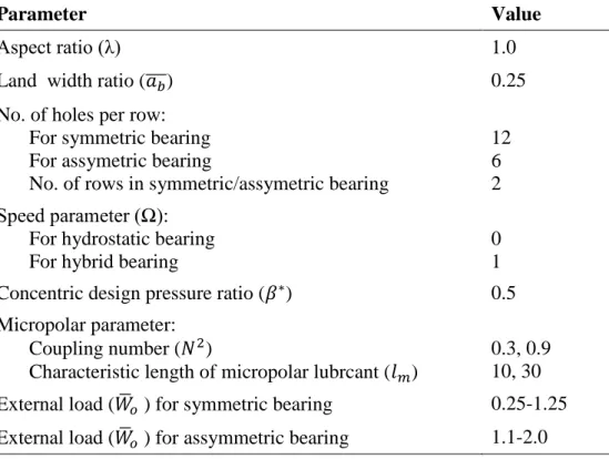
A computer program has been developed which is based on analytic model to evaluate the symmetric and asymmetric hole-entry bearings compensated with capillary restrictor. The fluid film reaction (Figure 2) is computed and it is equated with the results given by Wang and Zhu. Bearing characteristics have been simulated with external load
(𝑊̅𝑜) for fixed value of concentric design pressure ratio as (𝛽∗= 0.5). The obtained results have been presented and compared with Newtonian lubricant at external load
𝑊̅𝑜 = 0.25 − 1.25 for symmetric bearing and 𝑊̅𝑜= 1.1 − 2.0 for asymmetric bearing corresponding to micropolar parameters 𝑁2 = 0.3, 0.9 and 𝑙
𝑚 = 10,30. The parameters used in the present work are given in Table 1.
At an axial mid-plane (𝛽 = 0.0) the distribution of circumferential fluid-film pressure for symmetric/asymmetric hydrostatic and hybrid bearings are shown in Figure 3(a,b) and Figure 4(a,b), respectively. It can be seen that the pressure (𝑝̅) for a micropolar fluid lubricated hydrostatic and hybrid bearing increases with increasing in coupling number 𝑁2. In the clearance space, values of micropolar parameters (𝑁2) and (𝑙𝑚) alters the thickness of fluid-film and the lubricant flow pattern of the journal bearing. Consequently in a journal bearing the pressure distribution also gets altered due to the effects of the above mentioned micropolar parameters. In the upper half (00 to 1800) of the bearing, the pressure is not much influenced by the micropolar lubricant but in the lower half (1800 to 3600) of the bearing, the higher value of coupling number 𝑁2
significantly increase the pressure distribution. Smaller clearance in the lower half of bearing, results in higher value of 𝑁2 for micropolar lubricant for the lower half (1800 to
Figure 2: Fluid film reaction (𝐹0) with eccentricity (ɛ) . The solid ine is from this study, while the dashed line is from other work (Wang and Zhu, 2006)
Table 1: Parameters used for the hole-entry hydrostatic/hybrid journal bearings
Parameter Value
Aspect ratio (λ) 1.0
Land width ratio (𝑎̅̅̅𝑏) 0.25
No. of holes per row: For symmetric bearing For assymetric bearing
No. of rows in symmetric/assymetric bearing
12 6 2 Speed parameter (Ω):
For hydrostatic bearing For hybrid bearing
0 1 Concentric design pressure ratio (𝛽∗) 0.5 Micropolar parameter:
Coupling number (𝑁2)
Characteristic length of micropolar lubrcant (𝑙𝑚)
(a)
(b)
(a)
(b)
4.1 Minimum Fluid-Film Thickness (hmin)
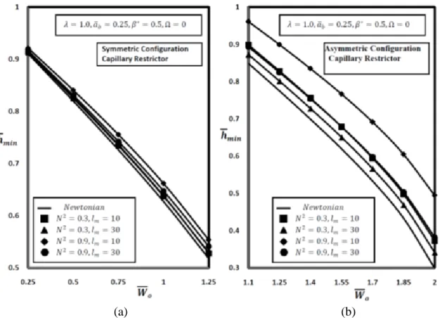
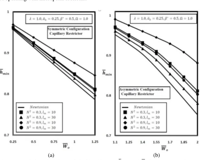
Figure 5 and Figure 6 show the effect of micropolar lubricant on minimum fluid film thickness (ℎ̅𝑚𝑖𝑛) for different values of external load(𝑊̅𝑜). The value of minimum fluid film thickness (ℎ̅𝑚𝑖𝑛) is seen to be increasing with an increasing value of coupling number 𝑁2 as shown in Figure 5(a) and Figure 5(b). The bearing lubricated with micropolar fluid having parameters 𝑁2 = 0.9, 𝑙𝑚= 10 gives larger minimum fluid-film thickness (ℎ̅𝑚𝑖𝑛) in symmetric and also in asymmetric hydrostatic bearing configurations. As the value of 𝑊̅𝑜 increases there is a reduction in ℎ̅𝑚𝑖𝑛 in symmetric and asymmetric bearing configurations. For asymmetric bearing, the micropolar lubricant effects is significant on minimum fluid-film thickness (ℎ̅𝑚𝑖𝑛) for lower 𝑊̅𝑜 (i.e. 𝑊̅𝑜 = 1.1) as shown in Figure 5(b). A similar trend can be observed for the value of minimum fluid-film thickness (ℎ̅𝑚𝑖𝑛) from Figure 6(a) and Figure 6(b) for symmetric and asymmetric hybrid bearing configuration.
(a) (b)
Figure 5: Variation of minimum fluid film thickness ℎ̅𝑚𝑖𝑛 and 𝑊̅𝑜 for (a) symmetric and (b) asymmetric configurations hydrostatic bearing
is observed to be 5.68% at 𝑊̅𝑜 = 1.0 and 6.33% at 𝑊̅𝑜= 1.4 for symmetric and asymmetric bearings respectively than bearing under Newtonian lubricant. Further it can be seen that the percentage increase in fluid-film thickness (ℎ̅𝑚𝑖𝑛) in symmetric hydrostatic bearing configuration is 5.53% at 𝑊̅𝑜 = 1.0 and 19.41% at 𝑊̅𝑜 = 1.4 operating with micropolar lubricant.
(a) (b)
Figure 6: Variation of minimum fluid film thickness ℎ̅𝑚𝑖𝑛 and 𝑊̅𝑜 for (a) symmetric and (b) asymmetric configurations hybrid bearing
4.2 Bearing Flow(𝑸̅)
to be 26.18% at 𝑊̅𝑜 = 1.0 and 21.10% at 𝑊̅𝑜= 1.4 in symmetric/asymmetric hydrostatic bearing respectively when comparing similar bearing lubricated with Newtonian fluid. Whereas, the reduction is observed to be 28.44% and 24% for symmetric/asymmetric hybrid bearing configuration respectively under micropolar lubricant having parameters
𝑁2 = 0.9, 𝑙𝑚 = 10.
(a) (b)
(a) (b)
Figure 8:Variation of bearing flow 𝑄 and 𝑊̅𝑜 for (a) symmetric and (b) asymmetric configurations hydrostatic bearing
4.3 Friction Coefficient(𝑪̅𝒇)
(a) (b)
Figure 9: Variation of friction coefficient 𝐶̅𝑓and 𝑊̅𝑜 for (a) symmetric and (b) asymmetric configurations hybrid bearing
4.4 Fluid-Film Stiffness Coefficients(𝑺̅𝟏𝟏, 𝑺̅𝟐𝟐)
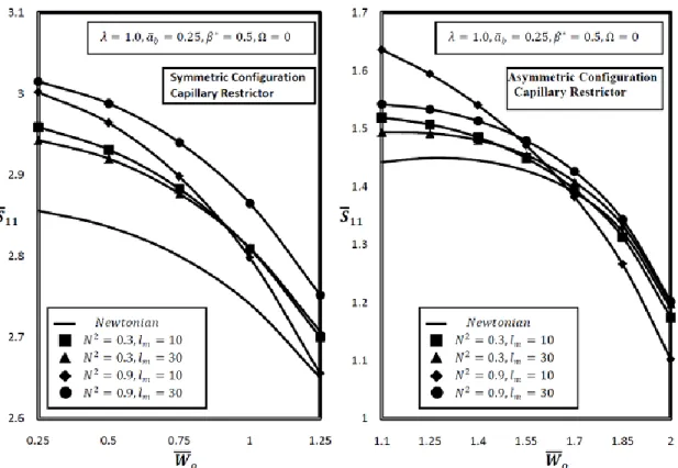
Figure 10 through Figure 13 presents fluid-film stiffness coefficients for micropolar parameters 𝑁2 and 𝑙
Figure 12: Variation of direct fluid film stiffness coefficient 𝑆̅22 with 𝑊̅𝑜 = 0
The percentage increase in 𝑆̅22 for asymmetric bearing with micropolar lubricant having parameters 𝑁2 = 0.9, 𝑙𝑚 = 10 is around 7.65% at 𝑊̅𝑜= 1.4 when compared to similar asymmetric Newtonian fluid lubricated bearing. It may be observed from Figure 12(a) that the direct stiffness coefficient (𝑆̅22) increases significantly for external load having constant value when micropolar lubricated bearing is used. In addition, it may be noted from Figure 13(b) that the value of 𝑆̅22 reduces till it achieve a particular value of external load and then start increasing afterwards for a micropolar and Newtonian lubricated bearing. For a chosen external load (𝑊̅𝑜), the value of direct stiffness coefficient (𝑆̅22) gets enhanced by 11.36% at 𝑊̅𝑜 = 1.4 corresponding to 𝑁2 = 0.9, 𝑙
𝑚 =
10 in asymmetric configuration for journal bearing lubricated with micropolar fluid than Newtonian fluid lubricated journal bearing.
4.5 Fluid-Film Damping Coefficients(𝑪̅𝟏𝟏, 𝑪̅𝟐𝟐)
Figure 14 through 17 displays the influence of micropolar parameters on damping coefficients. It may be noticed from Figure 14 and 15 that the damping coefficient (𝐶̅11)
value increases by increasing coupling number 𝑁2 for 𝑊̅
Figure 14: Variation of direct fluid film damping coefficient 𝐶̅11 with 𝑊̅𝑜 at = 0
4.6 Threshold Speed Margin ( )
Figure 18 presents the stability threshold speed margin (𝜔̅𝑡ℎ) for micropolar parameters. From Figure 18, it can be noticed that, for an increasing value of coupling number, the threshold speed (𝜔̅𝑡ℎ) increases at chosen values of load (𝑊̅𝑜) for both symmetric and asymmetric configurations. It also noticed that the asymmetric bearing with varying load (𝑊̅𝑜 < 1.55) under micropolar lubricant, has higher stability threshold speed margin (𝜔̅𝑡ℎ) when comparing with Newtonian fluid lubricated bearing for the same operating parameters. It is found that the percentage increase in 𝜔̅𝑡ℎ for a constant external load (𝑊̅𝑜 = 1.0) is 2.22% in case of symmetric configuration and for external load (𝑊̅𝑜 = 1.4) is 7.16% in case of asymmetric configuration lubricated with micropolar lubricant having parameters 𝑁2 = 0.9 and 𝑙
𝑚= 10.
CONCLUSIONS
1. The micropolar fluid lubricated bearings corresponding to parameters 𝑁2 = 0.9, 𝑙
𝑚 =
10 gives larger value of ℎ̅𝑚𝑖𝑛. It is further observed that the increase in fluid-film thickness for the symmetric hydrostatic bearing is 19.41% at 𝑊̅𝑜 = 1.4 operating under micropolar lubricant.
2. The horizontal and vertical stiffness coefficients(𝑆̅11, 𝑆̅22) increases for micropolar fluid lubricated bearing than similar bearing under Newtonian lubricant.
3. The value of damping coefficient (𝐶̅11) is observed 44.02% in case of symmetric hydrostatic bearing and 67.86% for asymmetric hydrostatic bearing lubricated with micropolar fluid than Newtonian lubricant.
4. A significant increase in damping coefficients is found for bearings having micropolar parameters, 𝑁2 = 0.9, 𝑙
𝑚 = 10 than Newtonian fluid lubricated bearing. 5. For external load (𝑊̅𝑜< 1.55), the asymmetric hybrid bearing under micropolar fluid
has shown higher stability threshold speed than bearing under Newtonian lubricant. 6. A reduction of 19.47% in friction coefficient is found at external load of 𝑊̅𝑜= 1.4
under micropolar parameters 𝑁2 = 0.9 and 𝑙𝑚= 10 for asymmetric hybrid bearing than bearing under Newtonian lubricant.
th
REFERENCES
Cheng, K., and Rowe, W.B., 1995. A selection strategy for the design of externally pressurized journal bearings. Tribology International, 28(7), 465-474.
El Kayar, A., Salem, E.A., Khalil, M.P., and Hegazy, A.A., 1983. Two-dimensional finite difference solution for externally pressurized journal bearings of finite length. Wear, 84(1), 1-13.
Eringen, A.C., 1966. Theory of micropolar fluids. J. Math. Mech., 16(1), 1–18.
Huang, T.W., and Weng, C.I., 1990. Dynamic characteristics of finite-width journal bearings with micropolar fluids. Wear, 141(1), 23-33.
Khonsari, M.M., 1997. On the modeling of multi-body interaction problems in tribology. Wear, 207(1-2), 55-62.
Kim, Y.J., and Kim, T.A., 2004. A study on the plane Couette flow using micropolar fluid theory. KSME international journal, 18(3), 491-498.
Krasowski, P., 2008. Pressure in slide journal bearing lubricated oil with micropolar structure. Journal of POLISH CIMAC, 1-9.
Lin, J.R., Chou, T.L., Liang, L.J., and Hung, T.C., 2012. Non-Newtonian dynamics characteristics of parabolic-film slider bearings: micropolar fluid model. Tribology International, 48, 226-231.
Lukasziewicz, G., 1999. Micropolar Fluids – Theory and Applications. Boston: Springer. Migun, N.P., 1981. Experimental method of determining parameters characterizing the microstructure of micropolar liquids. Journal of Engineering Physics, 41(2), 832-835. Ram, N., 2016. Performance of non-recessed hole-entry hybrid journal bearing operating
under turbulent regime. Jurnal Tribologi, 8, 12-26.
Ram, N., and Sharma, S.C., 2012. Analysis of orifice compensated non-recessed hole-entry hybrid journal bearing operating with micropolar lubricants. Tribology international, 52, 132-143.
Ram, N., and Sharma, S.C., 2015. Influence of Micropolar Lubricants on Asymmetric Slot-Entry Journal Bearings. Tribology Online, 10(5), 320-328.
Ram, N., Sharma, S.C., and Rajput, A., 2015. Compensated hole-entry hybrid journal bearing by CFV restrictor under micropolar lubricants. Proceedings of Malaysian International Tribology Conference 2015, 171-172.
Rowe, W.B., 1989. Advances in hydrostatic and hybrid bearing technology. Proceedings of the Institution of Mechanical Engineers, Part C: Journal of Mechanical Engineering Science, 203(4), 225-242.
Rowe, W.B., 1983. Hydrostatic and Hybrid Bearing Design. Butterworth-Heinemann Scott, W., and Suntiwattana, P., 1995. Effect of oil additives on the performance of a wet
friction clutch material. Wear, 181, 850-855.
Shukla, J.B., and Isa, M., 1975. Generalized Reynolds equation for micropolar lubricants and its application to optimum one-dimensional slider bearings: Effects of solid-particle additives in solution. Journal of Mechanical Engineering Science, 17(5), 280-284.
Singh, C., and Sinha, P., 1981. Dynamic loading of micropolar fluid lubricated short journal bearings. Journal of Mechanical Engineering Science, 23(1), 37-44.
Wang, X.L., and Zhu, K.Q., 2006. Numerical analysis of journal bearings lubricated with micropolar fluids including thermal and cavitating effects. Tribology International, 39(3), 227-237.