Proceedings of the
12th International Workshop on Graph Transformation
and Visual Modeling Techniques
(GTVMT 2013)
A Pattern-based Approach for Initial Diagram Layout
Sonja Maier and Mark Minas
14 pages
Guest Editors: Matthias Tichy, Leila Ribeiro
Managing Editors: Tiziana Margaria, Julia Padberg, Gabriele Taentzer
A Pattern-based Approach for Initial Diagram Layout
Sonja Maier1and Mark Minas2
1[email protected] 2[email protected]
Universit¨at der Bundeswehr M¨unchen
Abstract: In a diagram editor, one can distinguish initial from incremental diagram layout. The former computes a diagram layout from scratch, whereas the latter adjusts an existing layout after diagram modifications.
In previous work, we have proposed a pattern-based approach as a solution for in-cremental diagram layout in visual language editors. Each LP encapsulates certain layout behavior. A diagram’s layout is then defined by simultaneously applying several LPs to the diagram. This solution has been designed for an interactive en-vironment where the user may select and alter the layout behavior at runtime. This paper describes an extension of this approach that now supports initial diagram lay-out, too. While the old version only enabled freehand editing, the extended version now supports diagram import and structured editing as well.
Keywords:layout, diagram editor, freehand & structured editing, diagram import
1
Introduction
A layout engine usually runs continuously within diagram editors and improves the layout in response to user interaction in real-time. Layout improvement includes all sorts of changes concerning the position or shape of diagram components. A powerful and flexible layout engine is needed in order to enable or to improve the usability of different modes of operation, such as freehand editing, structured editing or diagram import. We have developed apattern-based approach[MM12,Mai12], which is tailored to such an interactive environment.Layout patterns (LPs)allow to encapsulate different kinds of layout algorithms and make them easily reusable for many different types of diagrams. The approach depends on acontrol algorithmfor computing a diagram layout that is determined by different LP instances. With the help of the approach, the complex task of layout computation can be split up into rather small pieces.
The layout of a diagram is defined by applying LPs to selected sub-diagrams. Applying an LP to a sub-diagram means creating an LP instance and binding it to this sub-diagram. The LP in-stance then contributes to automatic layout, i.e., its layout algorithm adjusts component variables according to the pattern’s specification. We distinguish two modes of operation which can be used simultaneously in the same diagram: Automatic applicationselects LPs and sub-diagrams automatically, controlled by the specification of the diagram syntax. Foruser-controlled appli-cation, the editor user selects diagram components that he would like to be arranged according to an LP and applies the corresponding LP to the sub-diagram consisting of this set of components. In a diagram editor, we distinguish different ways, a user can create and modify a diagram.
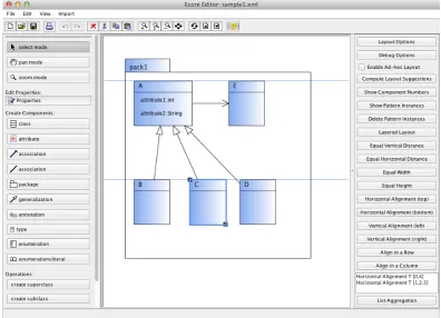
Figure 1: Class Diagram Editor
into other correct diagrams.Freehand editing, on the other side, means that the editor user may arrange diagram components on the screen without any restrictions. The third way a user can create a diagram, is importing a diagram from an abstract representation. This mode of operation is calleddiagram importin the following. We further distinguishinitialfromincremental (di-agram) layout. The former computes a diagram layout from scratch, i.e., without any previous layout information available, whereas the latter adjusts an existing layout after diagram modifi-cations. Freehand editing requires incremental layout, whereas diagram import requires initial layout. Structured editing requires both initial as well as incremental layout.
Up to now, the layout approach was used in the context of freehand editing only, and hence it solely supported incremental layout. In order to support initial layout, we extended the approach, mainly by generalizing the control algorithm. In this paper, we show that the slightly adapted approach is useful in the context of diagram import. We further present a small case study, which gives evidence that the approach works well in the context of model refactoring, and, hence, in the context of structured editing. As we will see, although the approach was primarily designed for incremental layout, the adapted version is also useful in the context of initial layout, and even can be utilized for a combination of both.
is more or less aligned with OMG’s EMOF (Essential MOF), which comprises the essential parts of OMG’s MOF. MOF is a so-called closed meta-modeling architecture, which defines the UML. Since class diagrams may contain a huge variety of different components, their Ecore model is quite complex. To keep the example simple, only a subset of components is considered in this paper, namely packages, classes, attributes, generalizations and associations. As can be seen in
Figure 1, these components are visualized as usual.
The paper is structured as follows: Section 2discusses related work. The extended pattern-based approach is sketched inSection 3. Section 4gives details of how to utilize our approach in the context of diagram import as well as in the context of structured editing.Section 5finally concludes the paper.
2
Related Work
Design patterns [GHJV95] serve as the formal basis of our pattern-based approach. In VL-Eli [Sch06], an editor generation framework, patterns are also used as a formal basis. In their ap-proach, tree grammars are used as the basis for specifying visual languages and layout, whereas we use meta-models instead. This design decision was made, because nowadays, meta-models are more widely used than grammars. In contrast to our approach, their approach does not sup-port freehand editing, and provides completely automatic layout only.
Dunnart [Wyb08] is an interactive system for drawing graph-based diagrams. Similar to our approach, their approach also has its strengths in the area of incremental layout, and also supports some sort of automatic and user-controlled layout.
A variety of layout algorithms exist that are tailored to one specific visual language. Most of these special-purpose layout algorithms are designed for completely automatic diagram layout only. In [Eig03], for instance, a topology-shapes-metrics approach for the automatic layout of UML class diagrams is presented. In [FSMH10], for instance, automatic layout and structure-based editing of UML diagrams is described.
Code refactorings are well known in software engineering. In case of class diagrams, the concepts can easily be lifted to models, which leads to model smells as well as model refactorings [Lan07]. Tools, such as EMF Refactor [Ecl12], enable, amongst others, the application of model refactoring operations. One weakness of such tools is often the integrated layout engine.
3
Pattern-based Layout Approach
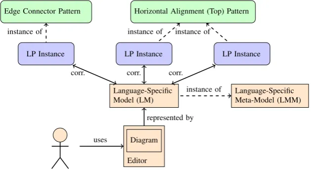
After the user has edited a diagram, the diagram’s LM is automatically created (updated). Furthermore, several LP instances are created (updated). Based on the LM and the LP instances, the new layout of the diagram is automatically computed, and the diagram is updated accordingly.
Editor Diagram Language-Specific Model (LM)
represented by
Language-Specific Meta-Model (LMM) instance of
Edge Connector Pattern
LP Instance
Horizontal Alignment (Top) Pattern
LP Instance LP Instance
corr. corr. corr. instance of instance of instance of
uses
Figure 2: Overview of the Approach
3.1 Concept of Layout Patterns (LPs)
A LP encapsulates certain layout behavior. An example is theedge connector pattern, which ensures that “edges” are correctly connected to “nodes”. Another example is the horizontal alignment (top) pattern, which makes sure that a set of “nodes” is horizontally aligned at the top. As can be seen in Figure 2, after the user has edited a diagram, several LP instances are created, and a correspondence between the LM and each of these LP instances is established. A LP may be instantiated one or more times for the same diagram. Its instantiation is either performed automatically, or it is triggered by the user. For instance, theedge connector pattern
is instantiated automatically. For the diagram shown inFigure 1, one pattern instance is created for the classesA,B,C,DandE together with the three generalizations and the association. In contrast, the instantiation of thehorizontal alignment (top) patternis triggered by the user. For the diagram shown inFigure 1, for instance, two pattern instances could be created - one for the classesAandE, and one for the classesB,CandD.
We distinguish two different types of LPs, namely continuously-applied LPs (CA-LPs)and
LP P-Constraint
Predicate
associated *
Rule
defined on top of PMM
LP Instance PM associated
*
instance of instance of
Figure 3: Layout Pattern (LP)
A LP (cf. Figure 3) is defined on top of a pattern-specific meta-model (PMM). It has one or more associated p-constraints (pattern-constraints), and each p-constraint consists of one predi-cate, which in turn has one or more associated rules. The predicates of all LP instances present in a diagram assure layout properties of the diagram. The layout of a diagram is correct if all predicates hold. The layout of a diagram is incorrect and needs to be updated if one or more predicates are broken. Each rule describes how the layout can be adjusted such that the broken predicate is repaired. The most commonly used types of rules are graph drawing algorithms, constraint-based (layout) algorithms and rule-based (layout) algorithms. Rule-based (layout) al-gorithms were introduced in [Mai12], and are specifically tailored to the interactive nature of diagram editors.
For instance, thehorizontal alignment (top) pattern has the associated predicatec1.y=c2.y. c1andc2are two components to be aligned.c1.yis they-position of the first component, andc2.y
is they-position of the second component. The predicate has the two associated rulesc1.y:=c2.y
andc2.y:=c1.y, which are rather trivial. For the example mentioned above, the predicate as well
as the associated rules are “instantiated” several times: For the alignment of the classesAand
E, they are instantiated for the pair of components{A,E}. For the alignment of the classesB,C
andD, they are instantiated for the pairs of components{B,C}and{C,D}.
3.2 Control Algorithm for Pattern Combination
The control algorithm for pattern combination is essentially a local propagation-based constraint solver that uses backtracking. The idea is that modifications made by the user, i.e., attribute changes because of user activity - e.g. moving a class - are “propagated” in the diagram. Its pur-pose is to find a valid layout after user modification, and hence, to compute a variable assignment for which all p-constraints (i.e. all predicates) are satisfied.
The control algorithm allows for the computation of the layout in the context of freehand editing. The generalized version of the control algorithm now enables the computation in the context of diagram import and structured editing as well. In the generalized version, the markings
Prior to the execution of the control algorithm, some variables are marked as toCheck, and some are marked as toCheck and frozen. The marking depends on the user interaction that triggers the execution of the control algorithm, and will be described inSection 4. During the execution of the control algorithm, some additional variables are marked astoCheckandfrozen. Starting with the variables that were marked as toCheck, all p-constraints are checked that involve these variables. For each violated p-constraint, meaning that the associated predicate is not satisfied, one of the corresponding rules is executed. These rules change one or more variables. All variables that are involved in the layout computation are marked astoCheckand
frozen. Again, all p-constraints are checked that involve the variables marked astoCheck. This procedure is continued until all p-constraints that need to be checked are satisfied. Backtracking is used if necessary. The first result found is chosen and the control algorithm stops immediately. If no solution can be found, the control algorithm signals a failure.
In one step, it might be the case that more than one p-constraint needs to be repaired, and hence, more than one rule needs to be executed. For that purpose, the control algorithm deter-mines an ordered list of these p-constraints based on a prioritization scheme, which is defined by the editor developer. Furthermore, if a p-constraint is violated, there might be several rules available to “repair” this violation. To do so, the control algorithm determines an ordered list of these rules based on a prioritization scheme, which is also defined by the LP creator. Starting with the ordered list of p-constraints and the ordered lists of rules, the rules are tried out by back-tracking until the control algorithm terminates either by finding a new assignment satisfying all p-constraints, or by signaling a failure.
3.3 Layout in the Class Diagram Editor
In the class diagram editor, several LPs are available. The application of the following ones is automatically performed: Thenode overlap removal patternmakes sure that components do not overlap. It is automatically applied to classes and packages on the same level, i.e. inside the same package. The edge connector patternmakes sure that edges are correctly connected. It is automatically applied to classes, together with generalizations and associations. Theminimal size component patternmakes sure that components are larger than a minimal size. It is auto-matically applied to classes as well as packages. Thelist patternmakes sure that components inside a container are arranged as a list and that they are correctly contained in the container. It is automatically applied to the attributes inside a class. Therectangular containment patternmakes sure that components are correctly nested. It is automatically applied to classes and packages.
The application of the following LPs is controlled by the user: The layered layout pattern
arranges components by the help of a layered layout algorithm. It may be applied to classes together with generalizations. Theequal horizontal distance patternas well as theequal vertical distance patternmake sure that components are placed equally distant to each other. They may be applied to packages and classes. Theequal height patternas well as theequal width pattern
4
Diagram Import, Structured Editing & Model Refactoring
As mentioned inSection 3, user interactions trigger the execution of the control algorithm. Be-fore extending our approach, the control algorithm was executed after the user had performed freehand editing, i.e. after he had created, modified or deleted one or more components. It was also executed after the user had applied a TA-LP to a user-selected set of components. After extending our approach, the control algorithm is now also executed after the user has imported a diagram from an abstract representation, or after the user has performed a structured editing operation. Prior to the execution of the control algorithm, some variables are marked astoCheck, and some astoCheckandfrozen, depending on one of the following situations:
• Freehand editing: All variables of all components that are modified by the user are marked astoCheckandfrozen.
• User applies a TA-LP: All variables ofone of the components, the TA-LP is applied to, are marked astoCheckandfrozen. This component is (usually) the component that was selected first by the user. All variables of the other components, the TA-LP is applied to, are marked astoCheck.
• Diagram import: The imported diagram consists of several components. All variables of all these components are marked astoCheck.
• Structured editing: Several components take part in the structured editing operation. All variables of all these components are marked astoCheck. Some of them are (optionally) marked asfrozenas well.
During the execution of the control algorithm, usually only a small subset of p-constraints that are present in the diagram needs to be checked. In case of diagram import, all p-constraints need to be checked, and hence, performance seems to be an issue. But this is only a minor issue, as the control algorithm only needs to be executed once after diagram import.
4.1 DiaMeta Architecture
The class diagram editor, our running example, was built by the help of DiaMeta [Min06], an editor generation framework. An overview of the architecture of a DiaMeta editor is shown inFigure 4. The abstract syntax and some aspects of the concrete syntax of the diagram are represented by the graph model. The graph model is internally transformed into the LM, which forms the basis for layout computation. Freehand editing operates on the diagram itself, whereas diagram import as well as structured editing both operate on the graph model.
After the editor user draws a diagram, the graph model is created on the basis of the diagram. An LMM instance LM is created on the basis of this graph model. Based on the LM, all LP instances are created. Some of these instances are automatically created, whereas others are created by the editor user. The layout engine gets the LM as well as all LP instances as input and computes the layout. After layout computation, all variable changes are collected, and the diagram is updated. Based on the changed diagram, the graph model, and the LM are updated automatically.
Diagram
Graph Model
LM
transformed
represented by
LP Instance
LP Instance Layout Engine
edits (freehand editing)
edits (structured editing & diagram import)
creates (TA-LP)
creates (CA-LP & TA-LP)
updates variable values
correspondence
input
Figure 4: Integration into DiaMeta
(a) Diagram (b) Graph Model
Figure 5: Internal Representation of a Class Diagram
connected to other diagram components. In class diagrams, a class, for instance, has its border as attachment area, and an association has its start point and its end point as attachment areas. Con-nections can be established by spatially related attachment areas. In class diagrams, for instance, an association has to start or end at the border of a class in order to be connected to this class. In the graph model, each component is modeled by a node (component node). Each attachment area is also modeled by a node (attachment node). Edges (attachment edges) connect component nodes with all attachment nodes that belong to this component node. Furthermore, edges (rela-tionship edges) connect attachment nodes that are in rela(rela-tionship with each other. Figure 5(b)
shows the graph model of the diagram shown in Figure 5(a). Attachment nodes are drawn as black circles, component nodes as gray rectangles, attachment edges as thin black arrows and relationship edges as thick blue arrows.
4.2 Diagram Import
The diagram import module is specified by the editor developer. The specification consists of two parts: It is defined how the graph model is created from an abstract representation. Besides, it is specified which TA-LPs are applied to which parts of the diagram.
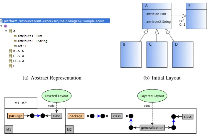
For the diagram that is represented inFigure 6(a), all variables are initialized with the value 0. The following instances of CA-LPs are automatically created: Instances of the minimal size component patternare created for the sets {A}, {B}, {C}, {D} and{E}of components. An instance of theedge connector patternis created for the set{A,B,C,D,E,g1,g2,g3,a1}of com-ponents. g1 is the generalization between A andB, g2 the one between A andC, g3 the one betweenAandD, and a1 the association between AandE. An instance of thelist pattern is created for the set{A,attribute1,attribute2}of components. In addition, an instance of a TA-LP is also automatically created, namely an instance of the layered layout pattern for the set
{A,B,C,D,E,g1,g2,g3}of components. The diagram is arranged as can be seen inFigure 6(b).
(a) Abstract Representation (b) Initial Layout
(c) Specification
Figure 6: Diagram Import
that are contained in this package. Pattern matching and LP instantiation is performed as shown inFigure 6(c): For each package, all contained classes (match of M1) and all contained gener-alizations (match of M2) are collected. For this set of components, onelayered layout pattern
instance is created, where classes play the rolenodeand generalizations the roleedge.
There might be cases in which it is not possible to compute a valid layout after diagram import. In such a scenario, in the worst case, a diagram import results in a diagram whose layout is incorrect. Whether or not such cases exist, again, depends on the set of LPs that is included in the editor, and the specification of the diagram import module, i.e., which TA-LPs are additionally applied. The existence of cases in which it is impossible to compute a valid layout gives evidence that the layout specification is inconsistent, and should be revised.
Up to now, we specified a diagram import module for a graph editor as well as a class diagram editor. In both cases, the import of an arbitrary diagram leads to a valid and acceptable layout. This result is promising, but does not give us a guarantee that the described proceeding suffices for other diagram editors as well. A more detailed evaluation is up to future work.
4.3 Structured Editing & Model Refactoring
Structured editingis quite interesting in terms of layout as it requires a combination of initial and incremental layout. In the context of structured editing, in most cases, the application of CA-LPs results in a valid and acceptable layout. In some cases, it makes sense to also automatically apply one or more TA-LPs to the sub-diagram, the structured editing operation is applied to.
Structured editing operations are defined by the editor developer. The specification consists of three parts: The structured editing operation itself is defined. Besides, it is specified which TA-LPs are applied to the sub-diagram, the structured editing operation is applied to. Finally, it is defined which variables are marked asfrozenprior to the execution of the control algorithm.
Model refactoring can be considered as structured editing with sophisticated editing opera-tions. In a small case study, several model refactoring operations were defined and integrated into the class diagram editor. The model refactoring operationsremove (inline) associated class,
remove (inline) superclass,remove (inline) subclass,push up (pull down) attribute, orpush up (pull down) methodrequired CA-LPs only. In contrast, the model refactoring operationscreate (extract) associated class,create (extract) superclass, or create (extract) subclassrequired the automatic application of TA-LPs in addition to the application of CA-LPs. These were the ones that incorporated the creation of classes and (or) packages.
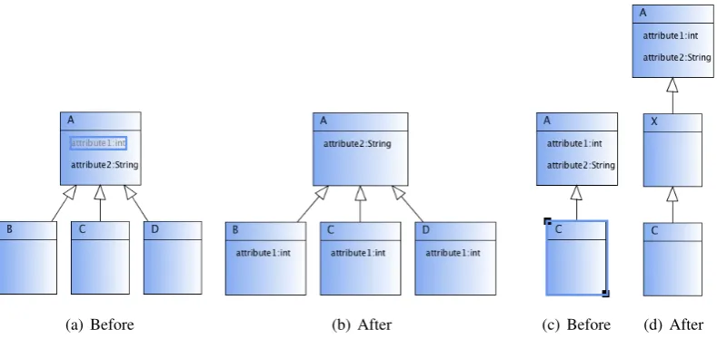
CA-LPs only For most model refactoring operations, the automatic creation of all instances of all CA-LPs turned out to be sufficient. An example is shown inFigure 7(a): The user has selected attributeattribute1 of typeintand has chosen the operationpull down attribute. As a consequence, the attributeattribute1 is deleted. Three new attributes are added to the classesB,
Figure 8(a)shows the graph model of the diagram before the model refactoring operation is performed, and Figure 8(b)afterwards, but before the layout is updated. Before layout com-putation, all variables that are shown in the right figure are marked astoCheck. During layout computation, the variables colored in red will be initialized by the layout engine, the variables colored in green will be updated by the layout engine, and the variables colored in black remain unchanged.
(a) Before (b) After (c) Before (d) After
Figure 7: Model Refactorings: Pull Down Attribute & Create Superclass
(a) Before Refactoring (b) After Refactoring, Before Layout Computation
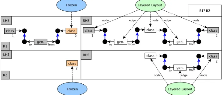
CA-LPs & TA-LPs In certain situations, the automatic creation of all instances of all CA-LPs may lead to an unacceptable or invalid layout. To improve this situation, the editor developer, who specifies the structured editing operation, has the possibility to define which TA-LP in-stances are automatically created. An example is shown inFigure 7(c)andFigure 7(d): The user has selected classCand has chosen the operationcreate superclass. That is why the generaliza-tion between the classesCandAgets deleted. Furthermore, the classX, and the generalizations
g1 betweenX andAandg2 betweenCandX get created. After creation, the classX is located at the position(0,0)and has the width and height 0. Both generalizations start and end at the position(0,0). During layout computation, amongst others, instances of theminimal size com-ponent patternand theedge connector patternare automatically created. In addition, an instance of a TA-LP is also automatically created, namely an instance of thelayered layout patternfor the set{A,X,C,g1,g2}of components. The model refactoring operation together with the LP instantiation is shown inFigure 9: The user-selected class is colored orange. One of the rules (R1 or R2) is applied, depending on whether or not a superclass exists. In both cases, onelayered layout patterninstance is created.
Figure 9: Create Superclass - Specification
To further improve the situation, the editor developer, who specifies a structured editing op-eration, has the possibility to define which variables are marked asfrozenprior to the execution of the control algorithm. For instance, in case of the operationcreate superclass, all variables of the component that was selected by the user are marked asfrozen. In the example, this is class
C. As a consequence, this component remains unchanged during layout computation.
Discussion In accordance to diagram import, there might be cases in which an unacceptable layout is produced after applying a structured editing operation. The existence of such cases gives evidence that the definition of the structured editing operation is incomplete, and that it should be extended. Also in accordance to diagram import, there might even be cases in which it is not possible to compute a valid layout afterwards. The existence of such cases gives evidence that the layout specification is inconsistent, and should be revised.
As already described, we specified several structured editing operations in the context of the small case study. The application of these structured editing operations to an arbitrary diagram leads to a valid and acceptable layout. This result is promising, but does not give us a guarantee that the described proceeding suffices for other structured editing operations as well. A more detailed evaluation is up to future work.
One interesting finding of the small case study was that the definition of the layout-part of the operations turned out to be straightforward. In contrast, the definition of the operations them-selves turned out to be a bit more challenging: As DiaMeta does not focus on structured editing, the transformation language provides basic concepts only. Besides, it has some limitations con-cerning the possible user input. E.g., the selection of an arbitrarily-sized set of components is not supported. Another interesting finding was that model refactoring operations require a rather complex user input. E.g., the model refactoring operationextract associated classrequires the user to select a class and an arbitrarily-sized set of attributes and methods of this class.
5
Future Work & Conclusions
In previous work, we have proposed a pattern-based approach as a solution for incremental lay-out in visual language editors. In this paper, an extension of this approach was described, which now supports initial layout, too. We showed that our pattern-based approach is also useful in the context of diagram import. Furthermore, the case study presented gives evidence that the approach works pretty well in the context of structured editing. With the approach, usually no “perfect” layout is achievable, but an acceptable one. Our general-purpose layout approach can-not compete with layout algorithms for diagram import or structured editing that are specifically designed for a visual language. But the nice thing is that layout support for diagram import and structured editing can be provided with very small effort.
The usability of our approach in the context of diagram import and structured editing heavily depends on the LPs that are integrated in the specific diagram editor. Hence, usability can be improved by defining additional LPs and including them in the diagram editor, or by slightly adapting one or more of the LPs that are already included in the diagram editor. But defining and including more and more LPs should not be exaggerated. More LPs means that the layout speci-fication is more complex, and that it is more challenging to build a consistent one. Furthermore, performance issues potentially arise.
We have included the layout approach in several DiaMeta- and GEF-editors, and already use it for diagram import as well as structured editing in three of them. Besides the authors of this paper, several students helped creating these editors, and experimented with them. This paper reported on the findings of this informal evaluation. A more formal evaluation is up to future work. It would include the creation of several editors, the integration of the layout approach into these editors, and the use of these editors for carefully selected tasks.
At the moment, we plan to extend the approach in two different ways: Up to now, the layout engine signals a failure if it is not able to compute a valid layout. As an alternative, the layout engine could also compute a partial layout. The choice, which p-constraints are satisfied after layout computation, and which ones are not, is a challenging task. We further plan to create diagram editors that are specifically intended to run on multi-touch enabled devices: Multi-touch gestures in combination with our layout approach opens up a variety of new possibilities.
Bibliography
[Ecl12] Eclipse: EMF Refactor.http://www.eclipse.org/modeling/. 2012.
[Eig03] M. Eiglsperger.Automatic layout of UML class diagrams: a topology-shape-metrics approach. PhD thesis, Eberhard-Karls-Universitaet Tuebingen, 2003.
[FSMH10] H. Fuhrmann, M. Spoenemann, M. Matzen, R. von Hanxleden. Automatic layout and structure-based editing of UML diagrams. InProceedings of M-BED’10. 2010.
[GHJV95] E. Gamma, R. Helm, R. Johnson, J. Vlissides.Design patterns: elements of reusable object-oriented software. Addison-Wesley Professional, 1995.
[Lan07] C. Lange. Assessing and improving the quality of modeling: a series of empirical studies about the UML. PhD thesis, Technical University Eindhoven, 2007.
[Mai12] S. Maier. A Pattern-based approach for the combination of different layout algo-rithms in diagram editors. PhD thesis, Universitaet der Bundeswehr Muenchen, 2012.
[Min06] M. Minas. Generating meta-model-based freehand editors. InProceedings of Gra-BaTs’06. Volume 1. ECEASST, 2006.
[MM12] S. Maier, M. Minas. Integration of a pattern-based layout engine into diagram edi-tors. InProceedings of AGTIVE’12. Springer-Verlag, 2012.
[SBPM09] D. Steinberg, F. Budinsky, M. Paternostro, E. Merks. EMF: Eclipse Modeling Framework 2.0. Addison-Wesley Professional, 2nd edition, 2009.
[Sch06] C. Schmidt. Generierung von Struktureditoren fuer anspruchsvolle visuelle Sprachen. PhD thesis, Universitaet Paderborn, 2006.