Proceedings of the
Seventh International Workshop on
Graph Transformation and Visual Modeling Techniques
(GT-VMT 2008)
On a Graph-Based Semantics for UML Class and Object Diagrams
Anneke Kleppe, Arend Rensink
16 pages
Guest Editors: Claudia Ermel, Reiko Heckel, Juan de Lara
Managing Editors: Tiziana Margaria, Julia Padberg, Gabriele Taentzer
On a Graph-Based Semantics for UML Class and Object Diagrams
Anneke Kleppe, Arend Rensink
[email protected],[email protected] Department of Computer Science
University of Twente, Enschede, The Netherlands
Abstract: In this paper we propose a formal extension of type graphs with notions that are commonplace in the UML and have long proven their worth in that context: namely, inheritance, multiplicity, containment and the like. We believe the absence of a comprehensive and commonly agreed upon formalisation of these notions to be an important and, unfortunately, often ignored omission. Since our eventual aim (shared by many researchers) is to give unambiguous, formal semantics to the UML using the theory of graphs and graph transformation, in this paper we propose a set of definitions to repair this omission. With respect to previous work in this direction, our aim is to arrive at more comprehensive and at the same time simpler definitions.
Keywords: UML, Class Diagram, Type Graph, Instance Graph, Graph Constraint
1
Introduction
Software industry is showing an increasing interest in model-driven development. Indeed, we have little doubt that the future lies in higher-level models to take the place of code, in all but the most performance critical domains. With this trend, however, the quality of those models is of increasing importance. By this we do not mean the quality of the product being modelled (which obviously is the final consideration) but rather of the modelling paradigm. Good models may not guarantee good software, but on the other hand, a bad (ambiguous, inconsistent or unclear) model can never be expected to yield a good end product, in particular if the transformation from model to software is largely automatic.
The quality of models is determined by many aspects, among we believe precision, consis-tency and completeness to be paramount. The precision of a model corresponds to the lack of ambiguity, or in other words, the degree to which the model will be understood in exactly the same way by different persons and tools during the software development process. Consistency formally means the existence of an (i.e., at least one) instance, or implementation, of the model, whereas completeness means the inclusion of all relevant aspects, or (in other words) the ability to predict the behaviour of the system under all circumstances.
provide an actual formal underpinning of this claim, or when they do, the semantics covers only a relatively small part of UML; for instance, [BELT04,LBE+07,KGKK02, TR05]. The most comprehensive is [VFV06], but even there such basic notions as multiplicities are missing. We see the absence of a more complete semantics as an important and regrettable omission, although from a purely formal standpoint, there is little challenge in providing the necessary definitions. The aim of this work is to bridge the gap between pure formalism and practicality.
Like the papers cited above, in this paper we distinguish the type and instance levels, or in other words, type graphs and instance graphs. We see a type graph as an intensional defini-tion of a set of instance graphs, namely, those instance graphs for which it is a correct type. Type graphs are then enriched with constraints that capture UML concepts such as bi-directional associations, multiplicities, collection types, inheritance, redefinition of associations, and com-position relationships. In this, we have based ourselves on the (verbal) descriptions in the UML 2.0 specification [OMG05].
In searching for the aforementioned balance between simplicity and expressiveness of the semantics, we have used the following guidelines:
• Instance graphs should be as simple and straightforward as we can make them, if necessary at the price of increasing their sizes. In other words, where there is a choice between enriching the formalism (resulting in more concise but more complex graphs) or using larger (sub-)graphs to encode complexity, we have tended to choose in favour of the latter.
• Type graphs should be as close to instance graphs as we can make them; the number of special features or decorations should be minimised.
We have achieved this by using the concept of a graph constraint, which is essentially a template for a logical formula on top of an ordinary (type) graph.
The remainder of this paper is structured as follows: after providing the basic definitions to set the stage in Section2, we discuss the graph constraints in Section 3. We consider these to be the heart of our contribution. In Section4we relate our constraints to the standardised UML concepts. Finally, in the conclusion (Section5) we come back to the above considerations and re-evaluate our choices.
Unfortunately, it is not possible to include the full set of definitions into this paper. A complete version can be found in [KR08].
2
Basic concepts
Names and namespaces. UML is a visual language; its “sentences” are diagrams. However, a major part of any diagram is still text, and so we need conventions for visualising text inside dia-grams. For this purpose, we define a set of identifiers ID, consisting of a name from a predefined universe Name, and a namespace from a set NS, defined as follows.
• An identifier is a pairhns,nameiof a namespace ns and a name name;
• There is a root or top namespace⊤ ∈NS;
To visualise an identifier we use a well-known notation, which is less cumbersome than the angular brackets: the name space and name are separated by a dot, and the top namespace is omitted altogether. Thus,hns,nameiis actually written ns.name.
For instance, the identifiera.name.spaceconsists of the namespacein the namespacea.name, which itself is an identifier with namespaceaand namename. The identifiera, finally, consists of the nameain the top name space.
Signatures and algebras. For our definition of model we use the notion of attributed type graph, as defined in [EPT04]. The ingredients of this definition that are important here are:
• A collection of data sorts Sort, which are in fact identifiers (hence Sort⊆ID)
• A collection of carrier sets Data, partitioned into subsets for each of the sorts in Sort.
Graphs. One of the core concepts of this paper is that of graphs. We start by repeating the usual definition of a directed, multi-sorted graph.
Definition 1 (graph) A graph is a tuple G=hNode,Edge,src,tgtiwhere Node is a set of nodes, Edge a set of (directed) edges, and src,tgt : Edge→Node are source and target functions, respec-tively.
Note that although this definition does not yet specify node or edge labels, the nodes and edges do have identities. In some circumstances it will be the case that Node,Edge⊆ID and the identities are actually meaningful to the reader; it then makes sense to include them in a visualisation of the graph. In particular, this is the case for type graphs — see below.
We will use two kinds of graph: instance graphs and type graphs. Both extend the notion of graph with some further structure. To start with instance graphs: these have an additional labelling function that associates an identifier with every node and edge. Furthermore, edges have indices, which are chosen from the set of natural numbers in such a way that the combination of source node, index and label together completely determine the edge.
Definition 2 (labelled graph) A labelled graph is a tuple IG=hNode,Edge,src,tgt,ix,labi wherehNode,Edge,src,tgtiis a graph and
• ix : Edge→Natis an indexing function assigning a natural number to every edge;
• lab : (Node∪Edge)→ID is a labelling of nodes and edges;
• For e1,e2∈Edge, if src(e1) =src(e2), ix(e1) =ix(e2)and lab(e1) =lab(e2), then e1=e2.
For a given node n∈Node and label a∈ID, the set of outgoing edges is defined by
out(n,a) = {e∈Edge|src(e) =n,lab(e) =a} .
The indices assigned by the function ix are used for two purposes:
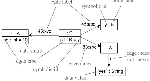
Figure 1: Example graphical representation of a labelled graph
• To order edges. One of the more powerful UML concepts is that of an ordered association; this does not only define a one-to-many relation between objects of one type to objects of another, but also establishes a local ordering over the set of (target) objects related to a single (source) object.
In contrast to edges, the encoding of node identities is not fixed by the above definition. It should, however, be understood that there is indeed some distinguishing mechanism, apart from the labelling function, that tells nodes apart. On the implementation level, for instance, this mechanism is typically based on memory addresses, or, for nodes in Node∩Data, by the data value. On the modelling level, the position within a diagram in principle suffices as the distin-guishing mechanism. On the other hand, for ease of reference it is very common to use symbolic names for nodes. Thus, we arrive at a graphical representation of labelled graphs based on the following conventions:
• Nodes are drawn as boxes with inscribed labels. The labels are preceded by a colon (‘:’). In front of a colon, there may either be a symbolic name, which is in fact itself an element of Name, but which plays no role in the formal meaning of the graph and in fact has no counterpart in Definition2; or, in the case of nodes that are actually data values, the string representation of the data value may be displayed. (We will see below that the label is typically the type, which for data values v∈Data is given implicitly by type(v).)
• Edges are drawn as arrows with superimposed labels. The labels may be preceded by a number representing the edge index, separated from the label by a colon; in particular, this is necessary if there is more than one outgoing edge with that label and the numbering is needed to determine an ordering.
• As an important special case, edges pointing to nodes that are explicitly identified, either by data values or by symbolic names, may be represented by inscribed equations of the form “label = id” or “label:Type = id” instead of arrows.
the graph, whereas10and“yes”are data values of type Intand String, respectively, and88,45 etc. are edge indices.
Graph morphisms. With respect to our aim of providing a sound and comprehensive formal-isation of UML concepts, one aspect is not yet completely covered, namely the fact that node identities and edge indices are not uniquely determined by the diagrams. In this sense, the formal interpretation of the diagrams remains ambiguous.
The reason why we are nevertheless content with this solution is that this ambiguity is not harmful, because the choice in no way matters to the actual meaning. Put differently, it is al-lowed to abstract away from the precise identities, provided the nodes and edges remain distin-guishable. The standard way to formalise this type of argument is by interpreting the structures under consideration — here, our graphs — up to or modulo some equivalence. In this particu-lar case, the standard way to define an appropriate equivalence is through the notion of graph isomorphism.
Definition 3 (graph (iso)morphism) Given two graphs G,H, a morphism from G to H is a pair of mappings f= (fNode: NodeG→NodeH,fEdge: EdgeG→EdgeH)such that
• Node and edge labels are preserved: labH◦(fNode∪fEdge) =labG;
• Sources and targets are preserved: srcH◦fEdge=fNode◦srcGand tgtH◦fEdge=fNode◦tgtG
f is an isomorphism if fNodeand fEdgeare bijective, i.e., provide a one-to-one mapping between NodeGand NodeH, resp. EdgeGand EdgeH. We write G∼=H (G is isomorphic to H) to denote that there is an isomorphism from G to H.
It is especially important to realise that (iso)morphisms are not required to either respect node identities or edge indices, symbolic names, or diagram layout.
For one particular purpose we will later on strengthen the requirements on morphisms, in such a way that the ordering on edge indices is sometimes required to be preserved; namely, when we use the index to reflect an ordering over the edges themselves.
Type graphs. For purposes of documentation, structuring and correctness, it is common to impose a discipline over labelled graphs, comparable to the grammar of programming languages, or more to the point here, comparable to a class diagram. In particular, we use a type graph to impose local constraints on the allowed labels and connections between edges and nodes, and associated constraints to impose other, more sophisticated or less local, properties.
Definition 4 (type graph) A type graph is a tuple TG=hNType,EType,src,tgt,inhiwhere
1. NType⊆ID is a set of node types and EType⊆ID a set of edge types;
2. hNType,EType,src,tgtiis a graph, with NType as node set and EType as edge set, such that src(e) =ns(e)for any e∈EType;
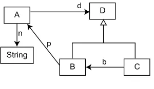
Figure 2: Example type graph
We typically use capital letters (T,E) to range over node and edge types.
The condition on the source function of edges (clause 2 in the definition) states that the source type of an edge is at the same time its name space. Since edge types are identifiers and identifiers are pairs of names and namespaces, it follows that edge types are uniquely determined by their source type and name. This setup allows us to use edge types with the same name, but only for distinct source types — which is consistent with the situation in most, if not all, object-oriented paradigms.
Also note that inh is a partial order, but not necessarily a forest: this implies that a node type can extend more than one other node type (in common terminology, our type graphs support multiple inheritance). At the same time, the partial order nature of inh implies that there can be no inheritance cycles.
For “node type” in the definition above, one may for most purposes read “class;” the only difference is that the node types typically include data sorts. We say that TG builds on a signature if Sort⊆NType.
A visual representation of a type graph can be given by drawing every node type as a box with the type identifier inscribed, every edge type as a “normal” arrow with the edge name as label, and every extension (i.e., from ext, not inh!) as an unlabelled arrow with triangular arrow head. Figure2shows an example type graph. This is very close to the traditional class diagram view, except that the data sorts are not treated as special cases (i.e., data type attributes are not distinguished from associations).
Typing and instance graphs. The meaning of a type graph is defined by the set of its (correctly typed) instances.1 The idea is that the instances of a type graph TG are labelled graphs with labels chosen from the types of TG, and consistent with the graph structure of TG modulo inheritance. To formalise it, we use the following auxiliary notation for arbitrary nodes n and node types T , resp. edges e and edge types E:
n:T :⇔ lab(n)inh T
e:E :⇔ lab(e) =E .
In words, n:T expresses that the label of the node n (in the instance graph under consideration) is a node type that inherits from T . Note that it follows that, for a given n, there can easily be more than one node type T such that n:T , ranging from T=lab(n)to all generalisations of T . On the other hand, in case of edges, e:E expresses that lab(e)is exactly the edge type E.
1 Strictly speaking, the meaning is defined by the category of instances and valid morphisms: as mentioned above,
Definition 5 (instance graph) Let TG be a type graph. A labelled graph IG is typed by TG, or an instance graph of TG, if for every node n∈Node and every edge e∈Edge:
• lab(n)∈NType and lab(e)∈EType; • src(e):src(lab(e))and tgt(e):tgt(lab(e)).
The set of instance graphs of TG is denoted Inst[TG](but see Footnote1).
For instance, the labelled graph in Figure 1 is not an instance graph of the type graph in Figure2, since it contains several edge labels that are not present in the type graph.
3
Constraints
The concepts introduced in the previous section are, in the sense of existing graph theory, straightforward; in fact, the only non-standard concepts are the structure we have chosen for identifiers, and the fact that we are using indexed edges in labelled (instance) graphs. In this sec-tion, we introduce a way to enrich type graphs, and so constrain the set of valid instance graphs, in ways that formalise the concepts found in UML.
First of all, we give a general definition of a constraint set over a graph; then, we define a series of special types of constraints tuned towards UML concepts.
Definition 6 (graph constraint) Let TG be a type graph. A constraint set over TG is a tuple hCon,sati where Con is a set of graph constraints, and sat⊆Inst[TG]×Con is a satisfaction relation over the instances of TG. We denote IG sat c to denote that an instance graph IG satisfies a constraint c.
This definition only specifies that a graph constraint is something for which there exists an interpretation, expressed in terms of the graphs that satisfy the constraint. The interpretation is embodied in the satisfaction relation, sat. The real question is how sat is defined. By combining type graphs with a constraint set, we arrive at the concept of a model, which is our equivalent to a UML class diagram.
Definition 7 (model) A model is a pair Mod=hTG,Coniwhere TG is a type graph, and Con is a constraint set over TG, consisting of constraints of the types listed below.
The main contribution of this work, apart from the selection of the appropriate type and in-stance graph definitions, lies in the definition of a number of useful graph constraint “templates” and the corresponding satisfaction relations. The constraints can be subdivided into a number of categories, listed in Table3. In this workshop paper, we can only discuss a few of the templates in detail; the report version [KR08] contains the complete list, in the same style as the ones reported here.
3.1 Association constraints: Bidirectionality
Table 3: A classification of constraints
Category Constraints
Node type Abstractness
Association Bidirectionality, Multiplicities, Indexing, Uniqueness
Containment Acyclicity, Unsharedness
Specialisation Subsetting, Redefinition, Union
General OCL
is in contrast to the graphs of this paper, where edges are unidirectional. To model bidirectional associations, we therefore need two edges, one for either direction, which oppose each other.
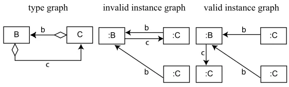
Definition 8 (bidirectionality constraint) Let TG be a type graph. A bidirectionality constraint over TG is a pairoppose(D,E)where D,E∈EType are edges in TG, such that src(D) =tgt(E) and tgt(D) =src(E). Satisfaction is defined for all G∈Inst[TG]by
G satoppose(D,E) :⇔ ∀n1:src(D),n2:tgt(D). |{d∈out(n1,D)|tgt(d) =n2}|=
|{e∈out(n2,E)|tgt(e) =n1}| .
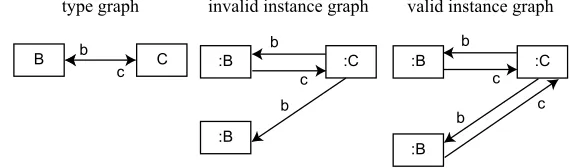
Figure4gives an example of a bidirectionality constraint. The type graph (left hand side) has an associated constraintoppose(B.c,C.b), visualised as a two-headed arrow. The centre graph does not satisfy this constraint, as there is aC.b-typed edge without an opposingB.c-typed one. In the right hand side graph this is repaired, so that this graph is a valid instance of the (enriched) type graph.
3.2 Association constraints: Indexing
To capture the notion of an ordered collection from class diagrams, we need to formalise what it means for a set of graph nodes to be ordered. To capture this correctly is actually quite involved, even though it is conceptually straightforward. Here we make use of the edge indices that are part of the instance graphs (see Definition5): if an edge type is declared as indexed, the edge indices have to be picked from a consecutive range from 1 upwards; and moreover (in fact, more importantly), morphisms are required to respect the edge indices.
Definition 9 (indexing constraint) Let TG be a type graph. An indexing constraint over TG is a predicateindexed(E), with E ∈EType. Satisfaction is defined for all G∈Inst[TG]and all
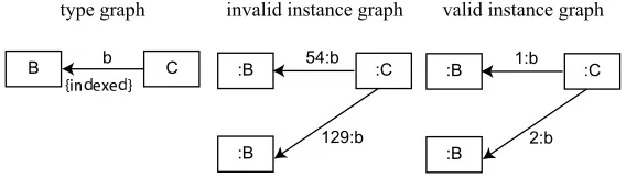
Figure 5: Example type graph with an indexing constraint
morphisms f between instance graphs G,H∈Inst[TG]by
G satindexed(E) :⇔ ∀n:src(E),∀e∈out(n,E).1≤ix(e)≤ |out(n,E)| f satindexed(E) :⇔ ∀e : E⇒ix(fEdge(e)) =ix(e) .
Figure5gives an example of an indexing constraint. The type graph (left hand side) has an associated constraintindexed(C.b), visualised by the annotation{indexed}near the arrow head. The centre graph does not satisfy this constraint, as it has two outgoing C.b-typed edges with indices {54,129}, which do not form a consecutive range. This is repaired in the right hand side graph. More importantly, where ordinarily the right hand side graph would be considered symmetric (having two interchangeableB-typed nodes), this is no longer true in the presence of the indexing constraint: the symmetry (formally, an isomorphism from the graph to itself) maps (n,C.b,1)to(n,C.b,2)(where n is theC-typed node in the graph) and hence does not satisfy the constraint, since it does not preserve edge indices.
3.3 Containment constraints: Acyclicity and unsharedness
Another notion from UML class diagrams that has proved to be quite useful in practice is that of aggregation or containment. Whereas ordinary edges may impose an arbitrary structure on the nodes they connect, containment is intended to reflect a hierarchy of things. Therefore, when edges in a type graph are declared to be acyclic, the intention is that the edges in the corresponding instance graphs do not form a cycle.
This type of constraint is in fact quite powerful if the edge types in the hierarchy do form a cycle in the type graph. In that case, there could in principle be instance graphs with arbitrarily large cycles, all of which are ruled out by a single acyclicity constraint. From this it can be seen that the acyclicity constraint is a non-local property, and hence outside the class of first-order logic.
Definition 10 (acyclicity constraint) Let TG be a type graph. An acyclicity constraint over TG is a tupleacyclic(E1, . . . ,En)where E1, . . . ,En∈EType is a collection of edge types. Satisfaction is defined for all G∈Inst[TG]by
G satacyclic(E1, . . . ,En) :⇔ {e:Ei|1≤i≤n}is cycle free.
Figure 6: Example type graph showing an acyclicity constraint.
of all diamond-decorated edge types. The case where a node or edge type can in principle be part of distinctacyclic-hierarchies cannot be visualised without adding further distinguishing information to the diamonds, for instance in the form of identifiers.) The centre graph of Figure6 shows a small instance of such a cycle; hence this graph violates the constraint. In the right hand side graph this is repaired, so that this is a valid instance of the (enriched) type graph.
The acyclicity constraint guarantees the absence of cycles (as its name suggests), but it does not guarantee the absence of sharing; in other words, on its own it is not certain that the structure imposed by acyclic edges is a forest. To complement this, we also introduce a constraint that specifies the absence of sharing; as will see, the UML composite is a combination of acyclicity and unsharedness. For an example unsharedness constraint, we refer to the technical report.
Definition 11 (unsharedness constraint) Let TG be a type graph. An unsharedness constraint over TG is a tupleunshared(E1, . . . ,En), where E1, . . . ,En∈EType. Satisfaction is defined for all G∈Inst[TG]by:
G satunshared(E1, . . . ,En) :⇔ ∀d:Ei,e:Ej.tgt(d) =tgt(e)⇒d=e .
3.4 Specialisation constraints: Redefinition
We have included node type inheritance as a basic notion in type graphs, reflecting the common concept from UML and other object-oriented settings. For edges, on the other hand, although there is likewise a notion of specialisation, but no single commonly accepted way to capture this. Instead, UML knows several ways to define specialisation-like relationships between edges, which we here formalise through edge type constraints.
These can be categorised as subset, redefinition and union constraints. The only type we discuss in this paper is redefinition; for the others see the technical report. Redefinition imposes a kind of “subtype” relation over edges, such that the supertype is overridden by the subtype. More precisely, if an edge type D redefines another type E, then a node of D’s source type may no longer have an outgoing E-type edge — instead, this should be a D-type edge.
Definition 12 (redefinition constraint) Let TG be a type graph. A redefinition constraint over TG is a pairredefine(D,E), where D,E ∈EType are edges in TG, such that src(D)inh src(E) and tgt(D)inh tgt(E). Satisfaction is defined for all G∈Inst[TG]by:
G satredefine(D,E) :⇔ ∄e:E.lasrc(e):src(D) .
Figure 7: Example type graph with a redefinition constraint
head. The centre graph does not satisfy the constraint, since there is anA.d-type edge going out of anF-type node. In the right hand side this is repaired, by changing the offending edge into an F.b-type; as a result, this instance graph satisfies the redefinition constraint.
4
UML Semantics
In this section, we will apply the general framework introduced above to UML class and object diagrams, thus providing a formal, graph-based semantics for these diagrams.
Class and object diagrams. The formal meaning of a UML class diagram is that it is a model. An overview of the mapping of UML class diagram concepts to the concepts in our framework can be found in Table 9. The model’s type graph can be easily recognized: each class in the diagram is a node and each directed association is an edge. Non-directed associations translate to pairs of edges with a bi-directionality constraint, where the edge labels correspond to the names of the association ends.
Most of the constraint types in our graph-based framework can also be easily recognized in a class diagram, for instance a bidirectionality constraint is shown in a class diagram in the same manner as we have shown in Figure4.
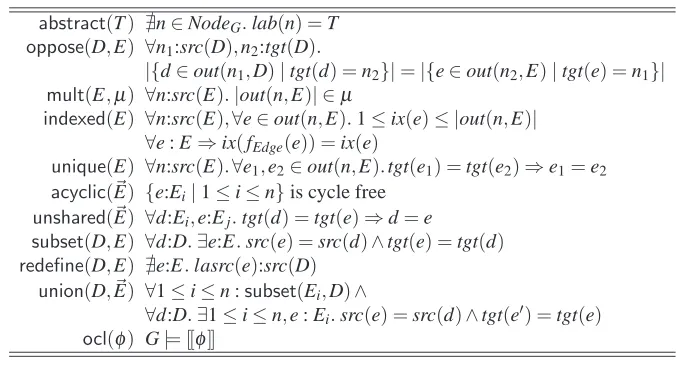
Table 8: Summary of all constraints — including those that are omitted from this workshop version; see the full report [KR08]. (Notation: ~E=E1· · ·En)
abstract(T) ∄n∈NodeG.lab(n) =T oppose(D,E) ∀n1:src(D),n2:tgt(D).
|{d∈out(n1,D)|tgt(d) =n2}|=|{e∈out(n2,E)|tgt(e) =n1}|
mult(E,µ) ∀n:src(E).|out(n,E)| ∈µ
indexed(E) ∀n:src(E),∀e∈out(n,E).1≤ix(e)≤ |out(n,E)| ∀e : E⇒ix(fEdge(e)) =ix(e)
unique(E) ∀n:src(E).∀e1,e2∈out(n,E).tgt(e1) =tgt(e2)⇒e1=e2
acyclic(~E) {e:Ei|1≤i≤n}is cycle free unshared(~E) ∀d:Ei,e:Ej.tgt(d) =tgt(e)⇒d=e
subset(D,E) ∀d:D.∃e:E.src(e) =src(d)∧tgt(e) =tgt(d) redefine(D,E) ∄e:E.lasrc(e):src(D)
union(D, ~E) ∀1≤i≤n :subset(Ei,D)∧
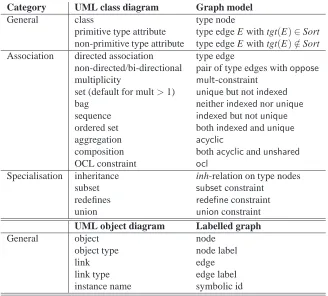
Table 9: Mapping of UML class diagram concepts to graphs
Category UML class diagram Graph model
General class type node
primitive type attribute type edge E with tgt(E)∈Sort
non-primitive type attribute type edge E with tgt(E)∈/Sort
Association directed association type edge
non-directed/bi-directional pair of type edges withoppose
multiplicity mult-constraint
set (default for mult>1) uniquebut notindexed
bag neitherindexednorunique
sequence indexedbut notunique
ordered set bothindexedandunique
aggregation acyclic
composition bothacyclicandunshared
OCL constraint ocl
Specialisation inheritance inh-relation on type nodes
subset subsetconstraint
redefines redefineconstraint
union unionconstraint
UML object diagram Labelled graph
General object node
object type node label
link edge
link type edge label
instance name symbolic id
UML class diagrams can be accompanied by OCL constraints. In our semantics, these are also translated to graph constraints, of the typeocl(φ)(omitted in this workshop paper) , by relying on the existing OCL semantics (which essentially provides a translation to first order logic). In other words, a class diagram together with its OCL constraints is translated to a model, in the sense of Definition7. This illustrates the fact that OCL constraints cannot be seen as separate from the class diagram. It will be no surprise that we define an object diagram to be a labeled graph. When a labeled graph satisfies a certain model, for instance a class diagram or a class diagram combined with constraints, it is a valid instance of that model. An overview of the mapping of UML object diagram concepts to the concepts in our framework can be found in Table9.
Evaluation. The semantics presented here should, as any semantics, uphold the commonly known characteristics of UML diagrams, even those that have (unfortunately) not been made explicit in the UML specification. As an example, we show two such characteristics; again, we refer the reader to [KR08] for a more comprehensive discussion. LethTG,Ci be the model representing the class diagram under consideration.
{sequence}. Likewise, if one end is an (ordered) set, the other end must be a set as well.
In our semantics, this situation arises when the bi-directionality constraint is combined with the uniqueness constraint. This UML characteristics then translates to the following “law” of graph constraints:
oppose(D,E)⇒(unique(D)⇔unique(E))
• According to the UML specification, the acyclicity constraint should always be combined with bi-directionality: “Only binary associations can be aggregations” ([OMG05], page 37). At the same time, only one end of this association can be marked as aggregate. This is in accordance with common sense, which says that a part cannot contain its container. In our framework this forbidden situation would occur when the acyclicity constraint is defined for both edges of a bi-directional association, i.e.:
oppose(D,E)∧acyclic(D)∧acyclic(E) .
In our semantics, there are no instances that would satisfy such a model; in other words, this combination of constraints is inconsistent (i.e., a contradiction).
These cases give confidence that the presented semantics really conforms to the intuition be-hind UML. On the other hand, our semantics does not support all UML aspects; in particular, the following are not included:
• Names of associations. Only the role names associated with the association ends are taken into account, because we consider these to be more important.
• N-ary associations, i.e. associations between more than two classes. These tend to occur very rarely in class diagrams; moreover, the UML specification itself treats them more like classes than like associations.
• Derived attributes or association ends. As the name suggests, these are derived values and need not be explicitly part of the formal representation.
• Navigability of associations. We feel that the directionality of the edges in the association pair provides enough information.
• Operations. These cannot be expressed by a static structure.
5
Conclusions
easily define class diagrams without abstract classes. Furthermore, our definitions do not only provide a semantics for both diagram types, but for the relationship between them as well.
As stated in the introduction, simplicity was one of our main guidelines. The only addition we made to the familiar notion of labelled graph is the edge indexing function, in order to capture ordered associations. We investigated (and rejected) several alternatives. The use of special “collection node types” makes the definition of instance graph much more complex. Another possibility is to use hypergraphs, but that in itself makes the model much more complex. A third option is to use special edges between the target nodes of an ordered association to represent the ordering, as we have done before in [KKR06]. The problem with this solution is that the ordering needs to be local not only to all edges of the given type, but also to the source node.
In the introduction we stated that the quality of models is determined by precision, consis-tency, and completeness. Our semantics provide a precise meaning to class and object diagrams. Furthermore, the consistency of a model, i.e. the existence of instances, can be checked using the given definitions. For instance, we can prove that a model with a bi-directional association that is an aggregate in both directions is inconsistent. Research into this “logic of UML models” has so far been scarce (see e.g. [MB07]). The completeness of a model cannot be guaranteed by our semantics. However, the semantics themselves are more complete than any other graph-based semantics that we have found in the literature. For instance, [BELT04,KGKK02,LBE+07] only visualise a type graph with inheritance as a UML class diagram, thus implying a graph-based meaning for class diagrams without actually defining an UML semantics. [VFV06] includes at-tributes, associations, and inheritance, but not containment, multiplicity, abstract classes, or edge specialisation.
As a next step, we intend to investigate the integration of our framework with the existing theory of graph transformation. An important issue is to reconciliate our encoding of indexed edges with the requirements of algebraic graph transformations.
A final point we would like to make goes back to the introduction, and concerns the (scientific) merit of the type of effort we have undertaken in this paper. We believe to have achieved a simple, intuitive and workable graph-based semantics. The fact that UML was conceived over a decade ago and still no graph-based semantics with this degree of completeness had been presented (in contrast to other theoretical bases, e.g., [LB98,Gei98,Ove99¨ ,Kna99,EK99,DJPV02,Ham05]), indicates that our undertaking was not trivial. Moreover, there is a great need for such semantics, if ever model-driven engineering is to become a dependable method. We know that many of the ideas brought together in this work have been presented earlier; however, the strength of this contribution lies in the particular combination of these ideas. All in all, we believe that the result should be judged not only on novelty, but on completeness, adaptability, and usability as well. If there is no well-defined forum where this type of effort can receive recognition, there will be no incentive, and the gap between theory and practice may remain with us forever.
Bibliography
[BELT04] R. Bardohl, H. Ehrig, J. de Lara, G. Taentzer. Integrating Meta-modelling Aspects with Graph Transformation for Efficient Visual Language Definition and Model Manipulation. In Wer-melinger and Margaria (eds.), Fundamental Approaches to Software Engineering (FASE). LNCS 2984, pp. 214–228. Springer, 2004.
[DJPV02] W. Damm, B. Josko, A. Pnueli, A. Votintseva. Understanding UML: A Formal Semantics of
Concurrency and Communication in Real-Time UML. In Boer et al. (eds.), Formal Methods
for Components and Objects (FMCO). LNCS 2852, pp. 71–98. Springer, 2002.
[EK99] A. Evans, S. Kent. Core Meta-Modelling Semantics of UML: The pUML Approach. Pp. 140–
155 in [FR99].
[EPT04] H. Ehrig, U. Prange, G. Taentzer. Fundamental Theory for Typed Attributed Graph
Transfor-mation. In Ehrig et al. (eds.), ICGT. Pp. 161–177. 2004.
[FR99] R. B. France, B. Rumpe (eds.). UML’99: The Unified Modeling Language - Beyond the
Standard. LNCS 1723. Springer, 1999.
[Gei98] R. Geisler. Precise UML Semantics Through Formal Metamodeling. In Andrade et al. (eds.),
Proceedings of the OOPSLA’98 Workshop on Formalizing UML. Why? How? 1998.
[Ham05] Y. Hammal. A Formal Semantics of UML StateCharts by Means of Timed Petri Nets.
In Wang (ed.), Formal Techniques for Networked and Distributed Systems (FORTE). LNCS 3731, pp. 38–52. Springer, 2005.
[KGKK02] S. Kuske, M. Gogolla, R. Kollmann, H.-J. Kreowski. An Integrated Semantics for UML Class, Object and State Diagrams Based on Graph Transformation. In Butler et al. (eds.),
Integrated Formal Methods (IFM). LNCS 2335, pp. 11–28. Springer, 2002.
[KKR06] H. Kastenberg, A. G. Kleppe, A. Rensink. Defining Object-Oriented Execution Semantics
Using Graph Transformations. In Gorrieri and Wehrheim (eds.), Formal Methods for Open
Object-Oriented Distributed Systems (FMOODS). LNCS 4037, pp. 186–201. Springer,
Lon-don, June 2006.
[Kna99] A. Knapp. A Formal Semantics for UML Interactions. Pp. 116–130 in [FR99].
[KR08] A. Kleppe, A. Rensink. A Graph-Based Semantics for UML Class and Object Diagrams. Ctit
technical report TR-CTIT-08-06, Department of Computer Science, University of Twente, Jan. 2008.
http://eprints.eemcs.utwente.nl/11963/
[LB98] K. Lano, J. Bicarregui. Semantics and Transformations for UML Models. In B´ezivin and
Muller (eds.), The Unified Modeling Language (UML). LNCS 1618, pp. 107–119. Springer, 1998.
[LBE+07] J. de Lara, R. Bardohl, H. Ehrig, K. Ehrig, U. Prange, G. Taentzer. Attributed graph trans-formation with node type inheritance. Theoretical Computer Science 376(3):139–163, May 2007.
[MB07] A. Maraee, M. Balaban. Efficient Reasoning About Finite Satisfiability of UML Class
Di-agrams with Constrained Generalization Sets. In Akehurst et al. (eds.), Model Driven
Ar-chitecture: Foundations and Applications (ECMDA-FA). LNCS 4530, pp. 17–31. Springer,
[OMG05] OMG. Unified Modeling Language: Superstructure. Technical report formal/05-07-04, OMG, 2005.
http://www.omg.org/cgi-bin/doc?formal/05-07-04
[ ¨Ove99] G. ¨Overgaard. A Formal Approach to Collaborations in the Unified Modeling Language.
Pp. 99–115 in [FR99].
[TR05] G. Taentzer, A. Rensink. Ensuring Structural Constraints in Graph-Based Models with Type
Inheritance. In Cerioli (ed.), Fundamental Approaches to Software Engineering (FASE). LNCS 3442, pp. 64–79. Springer, April 2005.
[VFV06] G. Varr´o, K. Friedl, D. Varr´o. Implementing a Graph Transformation Engine in Relational