EVALUATION OF REAL-TIME MOTION TRACKING ACCURACY
OF CUSTOMISED IMU SENSOR FOR APPLICATION IN A MOBILE
BADMINTON VIRTUAL REALITY TRAINING SYSTEM
Zahari Taha1, Yashim Wong1*, Muhammad Amirul Abdullah1, Yap Hwa Jen2, and
Wee Kian Yeo3
1Innovative Manufacturing, Mechatronics and Sports Lab (iMAMS),
Universiti Malaysia Pahang, Malaysia
2Center of Product Design and Manufacturing (CPDM),
Universiti Malaya, Malaysia
3National Sports Institute of Malaysia, Malaysia
*Email: [email protected]
(Received 1 December 2017; accepted 18 January 2018; published online 29 January 2018)
To cite this article: Taha, Z., Wong, Y., Abdullah, M. A., & Jen, Y. H. (2018). Evaluation of real-time motion tracking accuracy of customised IMU sensor for application in a mobile badminton
virtual reality training system. Movement, Health & Exercise, 7(1), 201-209. http://dx.doi.org/10.15282/mohe.v7i1.185
Link to this article: http://dx.doi.org/10.15282/mohe.v7i1.185
Abstract
Immersion is one of the most important aspects in ensuring the applicability of Virtual Reality systems to training regimes aiming to improve performance. To ensure that this key aspect is met, the registration of motion between the real world and virtual environment must be made as accurate and as low latency as possible. Thus, an in-house developed Inertial Measurement Unit (IMU) system is developed for use in tracking the movement of the player’s racquet. This IMU tracks 6 DOF motion data and transmits it to the mobile training system for processing. Physically, the custom motion is built into the shape of a racquet grip to give a more natural sensation when swinging the racquet. In addition to that, an adaptive filter framework is also established to cope with different racquet movements automatically, enabling real-time 6 DOF tracking by balancing the jitter and latency. Experiments are performed to compare the efficacy of our approach with other conventional tracking methods such as the using Microsoft Kinect. The results obtained demonstrated noticeable accuracy and lower latency when compared with the aforementioned methods.
Introduction
Virtual Reality (VR) is defined as a computer-generated environment which is observed from a first-person perspective where the user is able to interact freely with the objects in the environment, in real time (Steuer, 1992). This interactivity enabled VR to be used in a plethora of application ranging from entertainment, rehabilitation to even training. Focusing on training applications, VR enables for the user to experience the simulation of complex scenarios (Webb & Griffin, 2003) which could hone the perception and judgement thus increasing the skills of the user in that specific training regime (Bliss, James, & Philip, 1997). This, however, requires the VR system to have a high degree of immersion in order for it to be feasible for training applications. In sports, actions are fast, dynamic as well as complex causing the hardware and software requirements for a truly immersive VR system to be extremely high. An example of high hardware requirements attributed to high immersion is in Kilteni, Bergstrom, and Slater's (2013) research where OptiTrack’s accurate sensing system is needed to be able to create a high degree of immersion in a collaborative drumming virtual reality system. According to the research, if the tracking were poor, the illusion of the body ownership of the VR avatar would not be achieved as input motion would not be in sync with avatar motion. In terms of graphical hardware requirements, desktop PCs with a powerful Graphical Processing Unit (GPU) capable of generating life-like virtual objects and environment while outputting high frame-rates, at a minimum of 120 FPS is required in order for the VR system to be used for extended periods without any side effects such as nausea and motion sickness (Webb & Griffin, 2003). High processing power is also needed to compute the complex physics interactions between objects within the said VR environment.
The aforementioned system has a large downside to it, being very costly as well as difficult to employ. In this research, we made it our objective to develop a mobile virtual reality badminton training system that is at a fraction of the size and cost of conventional high-grade VR system while still being able to output comparable performance capabilities. To achieve this, we developed the following:
1. The VR system is developed to run on an Android smartphone. This phone acts as a head-mounted display (HMD) while processing both the graphics and physics engine of the VR system.
2. A custom racquet sensor that is small and light which acts as a tracking system for the user’s racquet swings.
3. A motion skeleton driving the VR avatar which is moved according to an inverse kinematic model taking only the motion input parameters from the Android HMD unit and the badminton racquet.
Methodology
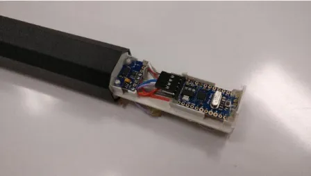
The racquet motion sensing system consists of a 6 degrees of freedom (DOF) IMU sensor, a battery unit and a Bluetooth sensor for transmitting motion data to the Android HMD unit. This whole circuitry is built into the racquet grip case and can be easily dismantled for removing the battery or any components in need of replacement via a sliding mechanism as shown in Figure 1.
Figure 1: Racquet Motion Sensor
In this study, racquet acceleration data is transmitted and recorded on to a desktop PC. The data is transmitted from IMU sensors to desktop PC via built-in Bluetooth transmitter with specifications given as in Table 1. The acceleration data captured is of 3-axis data namely X, Y and Z. Data is captured at a rate of 60 samples per seconds (60 Hz) in order for motion data captured using the IMU to be in synchronization with the motion data capture via video (60 frames per second (FPS) therefore 60 motion readings per second, as data from the video is frame-dependent). A simple averaging (mean filter) was applied in order to reduce noise from the IMU sensor readings.
Table 1: Racquet sensor technical specification
Dimension 30 mm x 32 mm x 140 mm
(Standard badminton racket handle) Communication Type, Data Transmission
Rate, Sensitivity & Effective Transmission Distance
Bluetooth 2.0, 3 Mbps (in HCI mode), -82 dB, 25 meters (In open, unobstructed space)
Microcontroller Arduino Pro Mini 3.3V 8MHz
Data Capture Rate 60 Hz
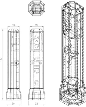
The racquet grip case which houses the aforementioned circuit is custom-designed referencing standard badminton racquet size and dimensions, as shown in Figure 2. The whole racquet grip is fabricated from scratch using 3D Printing. The 3D Printing material used is Acrylonitrile butadiene styrene (ABS), making the printed component lightweight and able to withstand rapid swings and drop impacts. In addition to that, the components are arranged in a way that the centre of gravity matches actual badminton racquet grips giving a more natural feel when using it. However, the racquet grip in terms of weight is far lighter than conventional racquet grips giving a “head-heavy” feel when swinging.
Figure 2: Schematic diagram for custom made racquet sensor
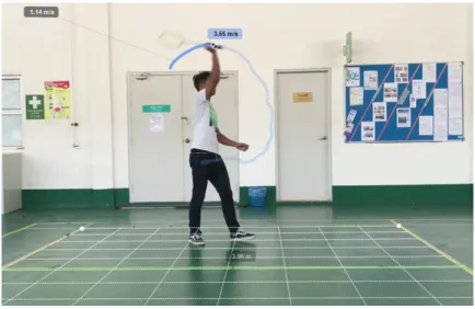
In order to compare the accuracy of the IMU readings, a motion capture video camera is set up to record the motion of the subject. A video camera with a resolution of 1920 x 1080 pixels and a frame capture rate of 60 FPS is employed to record the video of a subject using the IMU sensor to perform various badminton swings. Kinovea, an open source motion analysis software is used to analyse the recorded video. In order to obtain the accurate motion data from the video, the pixel distance in the video must be appropriately calibrated based on the known length of a real-world object reference present in the video. The lengths of the court lines were used to calibrate the pixel distance in the video for the X-Y plane as well as well as the Y-Z plane. The green line in
Figure 3 is used for calibration of pixel distance (3.8 m for 984 units of pixel). The calibration grid setup is as shown in
Figure 3: Motion Analysis Performed in Kinovea. Labels show current swing speed
For this study, an amateur level badminton player is used as a test subject. The test subject was asked to perform 3 types of badminton swings as described in Table 2, with a repetition of 20 times each. The video is captured simultaneously with the IMU data capture. Acceleration is taken from the racquet grip centre as per the IMU sensor. Motion graphs are plotted, and differences in values between these two plots are calculated and averaged.
Table 2: Badminton swings performed
Swing Type No. of Trials
Smash 20
Forehand 20
Backhand 20
Results and Discussion
Smash Acceleration Plot
The smash acceleration plot in
Figure 4 shows a good agreement between video tracking and racquet IMU sensor readings. The average reading difference for 20 samples is 4.13% with an error range of 0.34% to 10.4% for X-Axis and while for the y-axis, average error is higher at 8.4% with a difference range of 1.2% to 28%, Peak smash acceleration is recorded at the X-Axis at 204 m/s2 while the peak acceleration is at 141 m/s2. As observed in
Figure 4: Smash Raw Acceleration Plot against Time for Both IMU and Video Tracking
Forehand Acceleration Plot
extrapolate the position causing acceleration plot plateauing due to algorithm guessing the out-of-vision racquet position.
Figure 5: Forehand Raw Acceleration Plot against Time for Both IMU and Video Tracking
Backhand Acceleration Plot
Figure 6: Backhand Raw Acceleration Plot against Time for Both IMU and Video Tracking
When compared with other mobile badminton sensing systems, our proposed VR Racquet is more simple to setup due to all data is being captured via a single sensor. This is a valid approach as studies in a similar badminton sensing system done by Kilteni and Gawin (2010) shows that the acceleration of the racquet alone can explain 70% variance of the shuttle velocities.
Conclusion
In conclusion, the proposed custom made Racquet IMU sensing system performs better than the video tracking method. The IMU sensor does not share the same characteristics that attributed to error reading than with video tracking as it does not have an effective working field. The sensitivity of the IMU sensor is also higher than video tracking methods as the sensitivity of video methods is dependent on the pixel count. The downside to IMU sensors, however, is the high jitter, and noise picked up by the sensor due to high sensitivity as exhibited in the result section.
Acknowledgement
The researchers would like to extend their gratitude to the National Sports Institute of Malaysia (ISN) for providing the grant for this study under the grant number ISNRG No.: 09/2015-10/2015.
References
Bliss, A., James, P., & Philip, D. (1997). The effectiveness of virtual reality for administering spatial. Presence: Teleoperators and Virtual Environments, 6, 73–86.
Jaitner, T. & Gawin, W. (2010). A mobile measure device for the analysis of highly dynamic movement techniques. Procedia Engineering, 2(2), 3005-3010.
Kilteni, K., Bergstrom, I., & Slater, M. (2013). Drumming in immersive virtual reality: The body shapes the way we play. IEEE Transactions on Visualization and Computer Graphics, 19(4), 597–605. https://doi.org/10.1109/TVCG.2013.29
McMahan, R. P. (2011). Exploring the Effects of Higher-Fidelity Display and Interaction for Virtual Reality Games (Doctoral Dissertation), 15–28.
Steuer, J. (1992). Defining Virtual Reality: Dimensions Determining Telepresence.
Journal of Communication, 42(4), 73–93. https://doi.org/10.1111/j.1460-2466.1992.tb00812.x