®
Altera Corporation 1
Selecting Sockets
for Altera Devices
January 1999, ver. 3 Application Note 80
Introduction
Surface-mount assembly places unique demands on the development and manufacturing process by requiring different CAD symbols for printed circuit board (PCB) layout, different soldering processes for production (reflow vs. wave solder), and different test and reliability issues.Socketing surface-mount devices allows you to ease some of the demands of surface-mount assembly. Conventional mounting techniques can be used on socketed devices, either by through-hole soldering them to a PCB or by mounting them onto a socketed carrier board for wire-wrap applications.
This application note discusses the following topics: ■ Mechanical considerations for J-lead sockets ■ Socket evaluation for J-lead packages
■ Socket evaluation for quad flat pack (QFP) packages
■ Socket evaluation for ball-grid array (BGA) packages (including FineLine BGA™ packages)
■ Socket evaluation for pin-grid array (PGA) packages ■ Packaging operations for wire-wrap applications ■ Socket and insertion/extraction tool manufacturers
Mechanical
Considerations
for J-Lead
Sockets
J-lead devices make contact with electrical sockets from either the bottom or the side of the leads. Depending on how the devices are held in place, the sockets can bend the leads and make the electrical contact unreliable. Accordingly, you must consider the type of package, the number of device insertions and removals, and the amount of lead deformation before choosing a socket.
Once a design enters the production phase, cost becomes a major concern. As a result, low-cost production sockets, designed to hold a device permanently and securely, are available. However, these sockets must exert a reasonable force on the device leads to prevent the device from popping out of the socket. After several insertions, this force can deform the leads, causing them to short out or fail to make contact and rendering the device unusable. Therefore, Altera strongly recommends using a burn-in socket during the design and development phases of a project, and a low-cost production socket during the production phase.
1 Burn-in sockets are zero-insertion-force (ZIF) sockets that do not deform a device’s leads.
AN 80: Selecting Sockets for Altera Devices
Production sockets must be chosen carefully. If a device must be removed more than 10 times, Altera recommends using non-deforming, low-insertion-force (burn-in) sockets. In high-stress environments (e.g., strong G-forces, thermal shock, and high humidity), sockets with high-insertion forces and optional retention clips are needed. To reduce the possibility of damaging device pins, most high-quality sockets include a standoff mechanism that prevents a device from being forced too far into a socket.
Socket
Evaluation for
J-Lead
Packages
Altera tested available production sockets for use with 44-, 68-, and 84-pin windowed ceramic J-lead chip carrier (JLCC) packages. Although tests were performed using JLCC packages, the following information also applies to plastic J-lead chip carrier (PLCC) packages. Each socket was subjected to three tests:
■ The change in the gap between the corner pins of each device was measured before and after each of 10 insertions.
■ Each pin of the socket was wired in series and tested for open circuits lasting longer than 10 µs. This open circuit test was performed while the socket was attached to a vibration block. The amplitude of vibration was 3.0 mm peak-to-peak at a frequency that oscillated between 10 Hz and 55 Hz in 1-minute cycles for 2 hours. The vibration test was performed on all three axes at a temperature of 70° C.
■ The actual point of contact between the socket pin and the device lead was photographed to determine the direction of the forces and the amount of surface contact between them.
AN 80: Selecting Sockets for Altera Devices
Altera tested sockets from eight manufacturers. Tables1 through 3 show the results of the 44-, 68-, and 84-pin production sockets that passed the open-and-short circuit test. Sockets are ranked by their ability to maintain the device’s pin integrity after multiple device insertions.
Table 1. Summary of 44-Pin Production Socket Analysis
Vendor & Part Number Comments
Thomas & Betts Corporation PCS-044A-1
Least pin deformation. Contact force has a downward component. No retainer clip option.
AMP, Inc. 821575-1
Moderate pin deformation. Contact force has a downward component. No retainer clip option.
Table 2. Summary of 68-Pin Production Socket Analysis
Vendor & Part Number Comments
Thomas & Betts Corporation PCS-068A-1
Least pin deformation. Contact force has a downward component. No retainer clip option.
ITT/Cannon Corporation LCS-68-12
Low pin deformation. Contact force has a downward component. Has a retainer clip option.
AMP, Inc. 821574-1
Moderate pin deformation. Contact force has a downward component. No retainer clip option.
Table 3. Summary of 84-Pin Production Socket Analysis
Vendor & Part Number Comments
Thomas & Betts Corporation PCS-084A-1
Least pin deformation. Contact force has a downward component. No retainer clip option.
ITT/Cannon Corporation LCS-84-12
Moderate pin deformation. Contact force has a downward component. Has a retainer clip option.
AMP, Inc. 822281-1
(for surface mount)
Moderate pin deformation. Contact force has a downward component. No retainer clip option. Designed for plastic packages.
AMP, Inc. 821573-1
Large pin deformation. Very tight fit. No retainer clip option. Due to pin deformation, Altera recommends a maximum of three insertions. Designed for ceramic packages.
FCI
QILE-84P-410T
Large pin deformation. Very tight fit. No retainer clip option. Due to pin deformation, Altera recommends a maximum of three insertions.
AN 80: Selecting Sockets for Altera Devices
Vendors may provide additional information about their products, such as material selection, prevention of solder ingress during wave soldering, or lead shape. Altera recommends qualifying sockets before committing to a particular vendor.
Table 4 shows the contact distances for Altera® packages. These
measurements should be used to select a socket, preferably with internal stand-offs, for use with Altera devices.
Socket
Evaluation for
QFP Packages
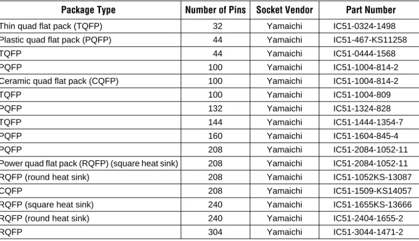
Because QFP packages are more susceptible to lead deformation, production sockets must be rigorously qualified. Altera recommends using a burn-in socket for QFP packages because of the socket’s reliability. While sockets should always be qualified, Table 5 suggests sockets based on the number of pins and type of QFP package.
Table 4. Device Contact Distances
Package Pins Contact Distance (Minimum mils) Contact Distance (Maximum mils)
PLCC 20 385 395
PLCC, JLCC 28 485 495
PLCC, JLCC 44 685 695
PLCC, JLCC 68 985 995
PLCC, JLCC 84 1,185 1,195
Table 5. Socket Vendor Information for QFP Packages
Package Type Number of Pins Socket Vendor Part Number
Thin quad flat pack (TQFP) 32 Yamaichi IC51-0324-1498 Plastic quad flat pack (PQFP) 44 Yamaichi IC51-467-KS11258 TQFP 44 Yamaichi IC51-0444-1568 PQFP 100 Yamaichi IC51-1004-814-2 Ceramic quad flat pack (CQFP) 100 Yamaichi IC51-1004-814-2 TQFP 100 Yamaichi IC51-1004-809 PQFP 132 Yamaichi IC51-1324-828 TQFP 144 Yamaichi IC51-1444-1354-7 PQFP 160 Yamaichi IC51-1604-845-4 PQFP 208 Yamaichi IC51-2084-1052-11 Power quad flat pack (RQFP) (square heat sink) 208 Yamaichi IC51-2084-1052-11 RQFP (round heat sink) 208 Yamaichi IC51-1052KS-13087
AN 80: Selecting Sockets for Altera Devices
Socket
Evaluation for
BGA Packages
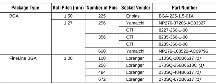
Table 6 lists socket vendor information for Altera BGA and FineLine BGA packages.
Note:
(1) These socket recommendations may change due to package enhancements. Please contact Altera Applications for more information.
Socket
Evaluation for
PGA Packages
Table 7 lists socket vendor information for PGA packages.
Table 6. Socket Vendor Information for BGA Packages
Package Type Ball Pitch (mm) Number of Pins Socket Vendor Part Number
BGA 1.50 225 Enplas BGA-225-1.5-01A 1.27 256 Yamaichi NP276-37206-AC03327
CTi 8227-256-1-00 356 CTi 8235-356-1-00 CTi 8235-356-0-00
600 Yamaichi NP276-100522-AC09796 FineLine BGA 1.00 100 Loranger 110SQ-100B6617 (1)
256 Loranger 170SQ-256B6618C (1)
484 Loranger 230SQ-484B6617 (1)
672 Loranger 270SQ-672B6617 (1)
Table 7. Socket Vendor Information for PGA Packages Number of
Pins
Socket Vendor Part Number
403 Yamaichi (1) NP178-64401-KS14828 AMP (1) 1-382320-7 Berg Electronics (2) Mill-Max (2) 503 AMP (1), (3) 382876-6 Yamaichi (1) NP236-102002-AC01601 3M/Textool (1) 2-0503-01357-050-019-002 Berg Electronics (2) Mill-Max (2) 599 Yamaichi NP236-102002-AC05625 Berg Electronics (2) Mill-Max (2)
AN 80: Selecting Sockets for Altera Devices
Notes:
(1) ZIF sockets are available for 403- and 503-pin PGA packages.
(2) This low-profile PCB socket has no standard part number. Contact the vendor for more information.
(3) Although the socket was created for 560-pin PGA packages, it is compatible with 503-pin packages.
Table 8 lists socket tools for inserting and extracting PGA packages in non-ZIF sockets.
Packaging
Operations for
Wire-Wrap
Applications
Wire-wrap applications require a through-hole mount that is compatible with the J-lead package. The sockets specified do not typically conform mechanically to most wire-wrap panels. Wire-wrap cards have machined receptacles in rows with 100-mil spacing between receptacles and 300-mil spacing between rows. Carrier boards provide an effective way to bridge the gap. Mounting a socket to a carrier board provides the convenience of wire wrap, while occupying a relatively small area on a device. Some carrier boards have signal routing with shorter paths or 45° bends to minimize signal reflection.
Socket &
Insertion/
Extraction Tool
Manufacturers
Table 9 shows telephone numbers for various socket manufacturers. Contact the appropriate manufacturer for additional information.
Table 8. Socket Tools for PGA Package Insertion & Extraction in Non-ZIF Sockets
Action Tool Vendor Part Number
Insertion Com-Kyl 181-MIC Extraction Com-Kyl 281-MIC
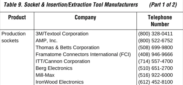
Table 9. Socket & Insertion/Extraction Tool Manufacturers (Part 1 of 2)
Product Company Telephone
Number
Production sockets
3M/Textool Corporation AMP, Inc.
Thomas & Betts Corporation
Framatome Connectors International (FCI) ITT/Cannon Corporation Berg Electronics Mill-Max (800) 328-0411 (800) 522-6752 (508) 699-9800 (408) 946-9666 (714) 557-4700 (510) 651-2700 (516) 922-6000
AN 80: Selecting Sockets for Altera Devices
Conclusion
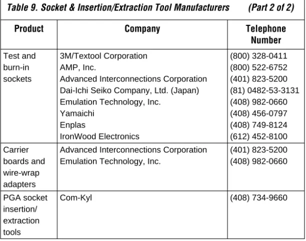
Information in this application note is based on tests performed by Altera and on information provided to Altera by various vendors. Altera assumes no liability for the use of third-party products mentioned in this document. Test and burn-in sockets 3M/Textool Corporation AMP, Inc.Advanced Interconnections Corporation Dai-Ichi Seiko Company, Ltd. (Japan) Emulation Technology, Inc.
Yamaichi Enplas IronWood Electronics (800) 328-0411 (800) 522-6752 (401) 823-5200 (81) 0482-53-3131 (408) 982-0660 (408) 456-0797 (408) 749-8124 (612) 452-8100 Carrier boards and wire-wrap adapters
Advanced Interconnections Corporation Emulation Technology, Inc.
(401) 823-5200 (408) 982-0660 PGA socket insertion/ extraction tools Com-Kyl (408) 734-9660
Table 9. Socket & Insertion/Extraction Tool Manufacturers (Part 2 of 2)
Product Company Telephone
®
Altera and FineLine BGA are trademarks and/or service marks of Altera Corporation in the United States and other countries. Altera acknowledges the trademarks of other organizations for their respective products or services mentioned in this document. Altera products are protected under numerous U.S. and foreign patents and pending applications, maskwork rights, and copyrights. Altera warrants performance of its semiconductor products to current specifications in accordance with Altera’s standard warranty, but reserves the right to make changes to any products and services at any time without notice. Altera assumes no responsibility or liability arising out of the application or use of any information, product, or
service described herein except as expressly agreed to in writing by Altera Corporation. Altera customers are advised to obtain the latest version of device specifications before
101 Innovation Drive San Jose, CA 95134 (408) 544-7000 http://www.altera.com Applications Hotline: (800) 800-EPLD Customer Marketing: (408) 544-7104 Literature Services: