International Journal of Trend in Scientific Research and Development (IJTSRD)
Volume 5 Issue 1, November-December 2020 Available Online: www.ijtsrd.com e-ISSN: 2456 – 6470
Design and Analysis of High Performance
Floating Point Arithmetic Unit
Naresh Kumar
1, Onkar Singh
2, Harjit Singh
31
M Tech Scholar,
2Assistant Professor, ECE Department,
3Assistant Professor, EEE Department,
1, 2, 3Arni University, Indora, Himachal Pradesh, India
ABSTRACT
A floating point arithmetic unit designed to perform operations on floating point numbers as well as fixed point numbers. Floating point numbers can support a much wider range of values in comparison to fixed point representation. Floating Point units are mainly used in high speed objects recognition system, high performance computer systems, embedded systems and mobile applications. To represent very small values or very large values, large range is required as the integer representation is no longer appropriate to represent these numbers so these values can be represented by using floating point representation that is based on the IEEE-754 standard. The proposed floating point arithmetic unit is designed using single stage implementation. Due to single stage implementation the complex logic operations which consist of various multiple numbers of stages are converted into single stage implementation. So by using single stage implementation the time requires to reach data from input to output becomes less. The proposed unit is designed in VHDL, simulated in Questa Sim simulator and implemented on vertex-7 FPGA.
KEYWORD: Vertex, Floating, Precision, Exponent, Fraction, Exception
How to cite this paper:Naresh Kumar |
Onkar Singh | Harjit Singh "Design and Analysis of High Performance Floating Point Arithmetic Unit" Published in International Journal of Trend in Scientific Research and Development (ijtsrd), ISSN: 2456-6470, Volume-5 | Issue-1, December 2020, pp.778-782, URL: www.ijtsrd.com/papers/ijtsrd38049.pdf
Copyright © 2020 by author(s) and International Journal of Trend in Scientific Research and Development Journal. This is an Open Access article distributed under the terms of
the Creative Commons Attribution
License (CC BY 4.0)
(http://creativecommons.org/licenses/by/4.0)
1. INTRODUCTION
An arithmetic circuit which performs digital arithmetic operations has many applications in digital coprocessors, application specific circuits, etc. Because of the advancements in the VLSI technology, many complex algorithms that appeared impractical to put into practice, have become easily realizable today with desired performance parameters so that new designs can be incorporated. The standardized methods to represent floating point numbers have been instituted by the IEEE 754 standard through which the floating point operations can be carried out efficiently with modest storage requirements. In computers the number will store if it have a finite precision. For scientific computation the numbers and arithmetic should meet certain few criteria-
Efficiency- Every arithmetic should be efficient to carry out.
Storage- Every number has a storage requirement. Portability- A level of portability should be there. That means the results of one computation should match with computation on other computers.
1.1. IEEE Single Precision Format: The IEEE single
precision format consists of 32 bits to represent a floating point number, divided into three subfields, as illustrated in figure 1.1
Sign Exponent Fraction
1 bit 8 bits 23 bits
Figure 1 IEEE single precision floating point format [4]
The first field is the sign bit for the fraction part. The next field consists of 8 bits which are used for exponent the third field consists of the remaining 23 bits and is used for the fractional part. The sign it reflects the sign of the fraction it is 0 for positive numbers and 1 for negative numbers.
1.2. IEEE Single Precision Format:
The IEEE double precision format consists of 64 bits to represent a floating point number, as illustrated in figure 1.3
S Exponent Fraction
1 bit 11 bits 52 bits
Figure 2 IEEE double precision floating-point format [4]
The first bit is the sign bit for the fraction part. The next 11 bits are used for the exponent, and the remaining 52 bits are used for the fractional part. As in the single precision format, the sign bit is 0 for positive numbers and 1 for negative numbers.
1.3. Advantages of floating Point Representation:
The main advantage of floating point format is that they have much wider range of values in comparison to fixed point format. Another advantage of floating point number is that they are more flexible than fixed point numbers which has a limited or no flexibility [5]. Other major advantages are there exponentially vastly increased dynamic range available for many applications. This large dynamic range is very useful in dealing with larger values. The internal representation of
data in floating point format is more exact than fixed point format [8].
1.4. Applications of floating-point representation
Scientific and higher engineering applications demand exceptionally high floating point performance which in turn requires high speed floating point units to reduce executing time. Floating Point units are used in high speed objects recognition system and also in high performance computer systems as well as embedded systems and mobile applications [2]. Floating point units are widely used in digital applications such as digital signal processing, digital image processing and multimedia [5]. In medical image recognition, greater accuracy supports the many levels of signal input from light, x-rays, ultrasound and other sources that must be defined and processed to create output images with useful diagnostic information. Wide dynamic range is essential to radar, where a system may need to track over a range from zero to infinity, and then use only a small subset of that range for target acquisition and identification. A wide dynamic range can also allow a robot to deal with unpredictable conditions, such as an obstruction to its normally limited range of motion. By contrast with these applications, the enormous communications market is better served by floating-point devices [8].
The floating point format is also very useful for audio and video applications. Audio needs wider range of values than video applications that requirement id fulfilled by floating point hardware [6]. Floating point unit performs addition, subtraction, multiplication, division, square root etc that are widely used in large set of scientific, commerce, financial and in signal processing applications [7].
2. Floating Point Arithmetic Unit
The block diagram of the proposed floating point arithmetic unit is given in figure 3. The unit supports four arithmetic operations: Add, Subtract, Multiply and Divide. All the basic mathematical arithmetic operations have been carried out in four separate modules one for addition, one for subtraction, one for multiplication and one for division.
The unit has following inputs:
1. Two 64-bit input operands
2. One 3-bit operation code (3 bits, 000 = add, 001 = subtract, 010 = multiply, 011 divide)
3. Rounding mode (2 bits, 00 = nearest, 01 = zero, 10 = possitive infinity, 11 = negative infinity)
4. Reset (Global) 5. Clock (Global)
Figure 3: Block Diagram of FPAU
The unit has following outputs:
1. 64-bit output 2. Five Exceptions 2.1.Inexact 2.2.Invalid 2.3.Overflow 2.4.Underflow 2.5.Divide-by-zero
In this design the operation to be performed on the 64-bit operands by a 3-bit operational code and the same operational code selects the output from that particular module and connects it to the final output of the unit. Particular exception signal will be high whenever that type of exception wills occur. In this design the complex logic operations segmented and implemented into various multiple numbers of stages are converted into single stage implementation in simple words we can say that the multiple stages are converted into single stage. Once the inputs are applied to the input terminals the final output is obtained at the output terminals there are no intermediate stages. So now the inputs take less time to reach at output terminals and due to single stage implementation the number of flip flops and other intermediate required circuits are less as a result the area require is less in the presented design.
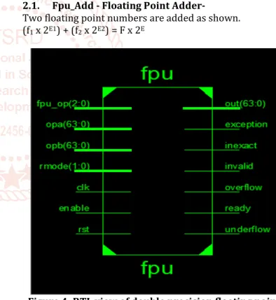
2.1. Fpu_Add - Floating Point Adder-
Two floating point numbers are added as shown. (f1 x 2E1) + (f2 x 2E2) = F x 2E
Figure 4: RTL view of double precision floating point arithmetic unit
In order to add two fractions, the associated exponents must be equal. Thus, if the exponents E1 and E2 are different, we
must normalize one of the fractions and adjust the exponents accordingly. The smaller number is the one that should adjusted so that if significant digits are lost, the effect is not significant.
The steps required to carry out floating point addition are as follows:
1. Compare exponents. If the exponents are not equal, shift the fraction with the smaller exponent right and add 1 to its exponent; repeat until the exponents are equal.
2. Add the fractions.
3. If the result is 0, set the exponents to the appropriate representation for 0 and exit.
4. If fraction overflow occurs, shift right and add 1 to the exponent to correct the overflow.
5. If the fraction is un normalized, shift left and subtracts 1 from the exponent until the fraction is normalized. 6. Check for exponent overflow. Set overflow indicator, if
necessary
7. Round to the appropriate number of bits.
2.2. Fpu_Sub- Floating Point Subtractor
Two floating point numbers are subtracted as shown. (f1 x 2E1 ) - (f2 x 2E2) = F x 2E
In order to subtract two fractions, the associated exponents must be equal. Thus, if the exponents E1 and E2 are different,
we must unnormalize one of the fractions and adjust the exponents accordingly. The smaller number is the one that should adjusted so that if significant digits are lost, the effect is not significant.
The steps required to carry out floating point subtraction are as follows:
1. Compare exponents. If the exponents are not equal, shift the fraction with the smaller exponent right and add 1 to its exponent; repeat until the exponents are equal. 2. Subtract the fractions.
3. If the result is 0, set the exponents to the appropriate representation for 0 and exit.
4. If fraction overflow occurs, shift right and add 1 to the exponent to correct the overflow.
5. If the fraction is un normalized, shift left and subtracts 1 from the exponent until the fraction is normalized. 6. Check for exponent overflow. Set overflow indicator, if
necessary
7. Round to the appropriate number of bits. Still normalized? Go to back to step 4.
2.3. Fpu_Mul- Floating Point Multiplier-
Two floating point numbers are multiplied as shown. (f1 x 2E1) x (f2 x 2E2) = (f1 x f2) x 2(E1+E2) = F x 2E
In this section, the design of multiplier for 64-bit floating point numbers is proposed. The fraction part of the product is the product of the fractions, and exponent part of the product is the sum of the exponents.
The general procedure for performing floating point multiplication is the following:
1. Add the exponents 2. Multiply the two fractions
3. If the product is zero, adjust the representation to the proper representation for zero.
A. If the product fraction is too big, normalize by shifting it right and incrementing the exponent. B. If the product fraction is too small, normalize by
shifting left and decrementing the exponent . 4. If an exponent underflow or overflow occurs, generate
an exception or error indicator.
5. Round to the appropriate number of bits. If rounding resulted in loss of normalization, go to step 3 again.
2.4.Fpu_Div- Floating Point Division
In this section, divider for floating point numbers is designed. It uses 4 bit fractions and 4 bit exponents, with
negative numbers represented in 2’s complement. Given two floating point numbers, the product is
(f1 x 2E1) / (f2 x 2E2) = (f1 / f2) x 2(E1-E2) = F x 2E
The floating point division is like a basic fixed point binary number division algorithm.
The general procedure for performing floating point division is the following:
1. Left shift divisor by the no. of bits and right shift dividend by no. of bits.
2. Compare the divisor with the dividend.
3. If divisor is greater than dividend set the corresponding quotient bit to zero.
4. If divisor is less than dividend subtract the divisor from the dividend and place the result in the divisor place, and put one in quotient position.
5. After each comparison right shift divisor by one position.
6. Repeat the above steps by the number of bits time. 7. The number in the dividend place gives remainder and
quotient place gives quotient.
2.5. Fpu_Round-Floating Point Rounding Unit-
Rounding module is used to modifies a number and fit it in the destination’s format. It is performed in the fpu_round module. From the core mathematical operations such as addition, subtraction, Multiplication and division the signals are given to fpu round part of unit. The fpu round perform rounding operation and in this unit four rounding modes are defined.
The standard defines the following four rounding modes
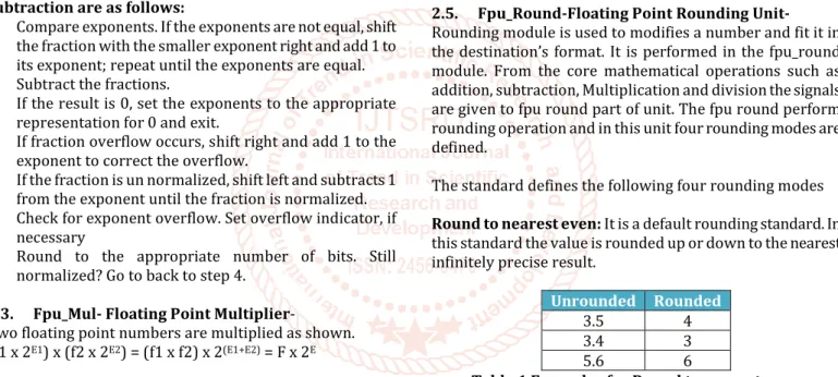
Round to nearest even: It is a default rounding standard. In
this standard the value is rounded up or down to the nearest infinitely precise result.
Unrounded Rounded
3.5 4 3.4 3 5.6 6
Table 1 Examples for Round to nearest even
Round-to-Zero: In this rounding mode the excess bits will
be truncated. e.g. 3.47 will be truncated to 3.5
Round-Up: In this rounding mode the number will be
rounded up towards positive infinity, e.g. 5.2 will be rounded to 6, while -4.2 to -4
Round-Down: In this rounding mode the number will be
rounded down towards negative infinity. e.g. 5.2 will be rounded to 5, while -4.2 to -5
2.6.Fpu_Exception- Floating Point Exception Unit-
The exceptions are occurring when an operation on any particular operands has no outputs suitable for a reasonable application.
The five exceptions are:
Invalid: The results which are not valid for any simple
application is called invalid exception. For example square root of a negative number etc., output of which does not exist.
Division by zero: This type of exceptions is occurs when there is infinite in the result. For e.g., 1/0 or log (0) that returns positive or negative infinity.
Overflow: This type of exception occurs when there are very
large values in the result. These large values cannot be represented correctly i.e. which returns ±infinity by default
Underflow: This type of exception occurs when there are
very small values in the result i.e. outside the normal range.
Inexact:This type of exceptionoccurs whenever the result of
an arithmetic operation is not exact due to the restricted exponent or precision range.
3. Results and Discussions:
The complete code is synthesis using Verilog, Simulate using Questa Sim Simulator which is an advance version of model sim simulator and implementation is done using Vertex-7 FPGA. The FPGA that is used for the implementation of the design is the Xilinx Vertex-7 (family), XC7VLX30 (Device), FF324 (Package) FPGA device. The working environment/tool for the design is the Xilinx ISE 12.4.1 is used for FPGA design flow of Verilog code.
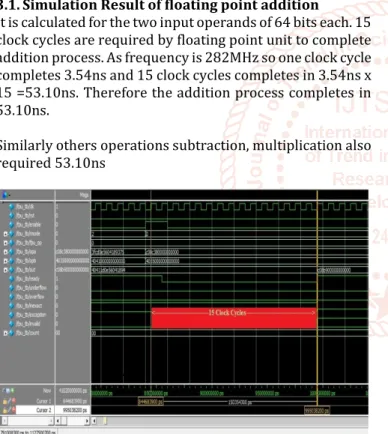
3.1.Simulation Result of floating point addition
It is calculated for the two input operands of 64 bits each. 15 clock cycles are required by floating point unit to complete addition process. As frequency is 282MHz so one clock cycle completes 3.54ns and 15 clock cycles completes in 3.54ns x 15 =53.10ns. Therefore the addition process completes in 53.10ns.
Similarly others operations subtraction, multiplication also required 53.10ns
Figure 5: Simulation Result of Floating Point Addition
3.2. Synthesis Results of Proposed FPAU:
The Table below showing the Area & Speed Results for floating point arithmetic unit implemented on vertex 7 FPGA
Logic Utilization Used Available
Number of Slice Registers 4762 437600 Number of Slice LUTs 6525 437600 Number of fully used LUT-FF pairs 3013 91200
Number of bonded IOBs 206 2680 Number of DSP48A1s 9 1680
Maximum Frequency 282 MHz Delay 53.10ns
Table 2: Design Summary of floating point arithmetic unit for vertex 7 FPGA
3.3. Timing Result of Proposed Floating Point Unit
Since addition requires 15 clock cycles and maximum frequency 282MHz so one clock cycle completes 3.54ns and 15 clock cycles completes in 3.54ns x 15 =53.10ns. Therefore the addition process completes in 53.10ns. Similarly subtraction operation completes in 53.10ns, multiplication operation completes in 53.10ns and division operation completes in 240.72ns (68 clock cycles)
4. Conclusions and Future Work
Floating point arithmetic unit has been designed to perform four arithmetic operations, addition, subtraction, multiplication and division on floating point numbers. The unit has been coded in VHDL. Code has been synthesised for the Virtex-7 FPGA board using XILINX ISE and has been implemented and verified on the software successfully. Single stage implementation techniques are utilized in the proposed floating point arithmetic unit. Due to single stage design implementation the longer combinational path can be compensated by shorter path delays in the subsequent logic stages and maximum frequency of the design will increased to 282 MHz. Iin the proposed floating point unit the complex logic operations which consist of various multiple numbers of stages are converted into single stage implementation. The proposed floating point unit takes 15 clock cycles for addition operation, 15 clock cycles for subtraction operation, 15 clock cycles for multiplication operation and 68 clock cycles for division operation. Proposed floating point unit consumed 6525 Slice LUT and 9 DSP48A1s.
The designed arithmetic unit operates on 64-bit operands and implemented on Virtex-7 FPGA it can also be implemented on high performance FPGA like Virtex- 8 FPGA. When the floating point unit implements on higher performance FPGA like Virtex-8 both the speed and area of the design will improve but the system becomes more costly. It can also be extended to have more mathematical operations like trigonometric, logarithmic and exponential functions. When such mathematical units are also implemented on the floating point unit it will work for more mathematical operations. We do not require other units to perform such operations but by implementing such extra mathematical units the floating point unit requires more area and system becomes more complex.
REFERENCES
[1] Yedukondala Rao Veeranki, R. Nakkeeran “Spartan 3E Synthesizable FPGA Based Floating-Point Arithmetic Unit” International Journal of Computer Trends and Technology (IJCTT), volume-4, Issue-4, pp.751-755, April 2013
[2] Jongwook Sohn, Earl E. Swartzlander “Improved Architectures for a Fused Floating Point Add-Subtract Unit” IEEE Transactions on Circuits and Systems-I: regular papers, Vol. 59, No. 10, pp. 2285-2291, October 2012
[3] KavithaSravanthi, Addula Saikumar “An FPGA Based Double Precision Floating Point Arithmetic Unit using Verilog” International Journal of Engineering Research & Technology (IJERT), Vol. 2 Issue 10, pp. 576-581, October - 2017
[4] H. Yamada, T. Hottat, T. Nishiyama, F. Murabayashi, T. Yamauchi, and H. Sawamoto “A 13.3ns Double-precision Floating-point ALU and Multiplier”, IEEE
International Conference on Computer Design: VLSI in Computers and Processors, pp. 466 – 470, 2-4 Oct 1995
[5] Addanki Puma Ramesh, A. V. N. Tilak, A.M.Prasad “An FPGA Based High Speed IEEE-754 Double Precision Floating Point Multiplier Using Verilog” 2013 International Conference on Emerging Trends in VLSI, Embedded System, Nano Electronics and Telecommunication System (ICEVENT), pp. 1-5, 7-9 Jan. 2017
[6] Ushasree G, R Dhanabal, Sarat Kumar Sahoo “Implementation of a High Speed Single Precision Floating Point Unit using Verilog” International Journal of Computer Applications National conference on VSLI and Embedded systems, pp.32-36, 2019 [7] Shamna. K, S. R Ramesh “Design and Implementation
of an Optimized Double Precision Floating Point Divider on FPGA”, International Journal of Advanced Science and Technology, Vol. 18, pp.41-48, May 2016 [8] Shrivastava Purnima, Tiwari Mukesh, Singh Jaikaran
and Rathore Sanjay “VHDL Environment for Floating point Arithmetic Logic Unit - ALU Design and Simulation” Research Journal of Engineering Sciences, Vol. 1(2), pp.1-6, August -2012
[9] Hwa-Joon Oh, Silvia M. Mueller, Christian Jacobi, Kevin D. Tran, Scott R. Cottier “A Fully Pipelined Single-Precision Floating-Point Unit in the Synergistic Processor Element of a CELL Processor” IEEE Journal of Solid-State Circuits, Vol. 41, No. 4, pp. 759-771, April 2006
[10] Tarek Ould Bachir, Jean-Pierre David “Performing Floating-Point Accumulation on a modern FPGA in Single and Double Precision” 18th IEEE Annual International Symposium on Field-Programmable Custom Computing Machines, pp.105-108, 2012 [11] Tashfia. Afreen, Minhaz. Uddin Md Ikram, Aqib. Al
Azad, and Iqbalur Rahman Rokon “Efficient FPGA Implementation of Double Precision Floating Point Unit Using Verilog HDL” , International Conference on Innovations in Electrical and Electronics Engineering (ICIEE'2012) , pp.230-233, Oct. 6-7, 2018
[12] Per Karlstrom, Andreas Ehliar, Dake Liu “High Performance, Low Latency FPGA based Floating Point Adder and Multiplier Units in a Virtex 4”, 24th Norchip
Conference, pp. 31 – 34, Nov. 2016.
[13] C. Rami Reddy, O. Homa Kesav, A. Maheswara Reddy “High Speed Single Precision Floating Point Unit Implementation Using Verilog” International Journal of Advances in Electronics and Computer Science, ISSN: 2393-2835 Volume-2, Issue-8, Aug.-2015 [14] Somsubhra Ghosh, Prarthana Bhattacharyya and Arka
Dutta “FPGA Based Implementation of a Double Precision IEEE Floating-Point Adder” , 7th International Conference on Intelligent Systems and Control (ISCO) pp.271-275, 4-5 Jan. 2013
[15] Liangwei Ge, Song Chen, yuichi Nakamura “ A Systhesis Method of General Floating Point Arithmetic Units by Aligned Partition”, 23rd International
Conference on Circuitd/Systems, Computers and Communications, pp. 1177-1180, 2018
[16] Dhiraj Sangwan , Mahesh K. Yadav “Design and Implementation of Adder/Subtractor and Multiplication Units for Floating-Point Arithmetic” International Journal of Electronics Engineering, 2(1), pp. 197-203, 2016
[17] Sameh Galal, Mark Horowitz “Energy-Efficient Floating-Point Unit Design” IEEE transactions on computers, Vol. 60, No. 7, pp. 913-922, July 2016 [18] Geetanjali Wasson “IEEE-754 compliant Algorithms
for Fast Multiplication of Double Precision Floating Point Numbers” International Journal of Research in Computer Science, Volume 1, Issue 1, pp. 1-7, 2014 [19] Tashfia. Afreen, Minhaz. Uddin Md Ikram, Aqib. Al
Azad, and Iqbalur Rahman Rokon “Efficient FPGA Implementation of Double Precision Floating Point Unit Using Verilog HDL” , International Conference on Innovations in Electrical and Electronics Engineering (ICIEE'2012) , pp.230-233, Oct. 6-7, 2012
[20] Monika Maan and Abhay Bindal “IMPLEMENTATION OF HIGH SPEED DOUBLE PRECISION FLOATING POINT UNIT ON FPGA USING VHDL” International Journal of Advanced Research in Science and Engineering, Vol No. 5, Issue No. 7, July 2018