DEFORMABLE BEAMSPLITTERS: ENHANCING PERCEPTION WITH WIDE FIELD OF VIEW, VARIFOCAL AUGMENTED REALITY DISPLAYS
David Dunn
A dissertation submitted to the faculty at the University of North Carolina at Chapel Hill in partial fulfillment of the requirements for the degree of Doctor of Philosophy in the Department
of Computer Science.
Chapel Hill 2019
© 2019 David Dunn
ABSTRACT
David Dunn: Deformable Beamsplitters: Enhancing Perception with Wide Field of View, Varifocal Augmented Reality Displays
(Under the direction of Henry Fuchs)
An augmented reality head-mounted display with full environmental awareness could present data in new ways and provide a new type of experience, allowing seamless transitions between real life and virtual content. However, creating a light-weight, optical see-through display provid-ing both focus support and wide field of view remains a challenge.
This dissertation describes a new dynamic optical element, the deformable beamsplitter, and its applications for wide field of view, varifocal, augmented reality displays. Deformable beam-splitters combine a traditional deformable membrane mirror and a beamsplitter into a single element, allowing reflected light to be manipulated by the deforming membrane mirror, while transmitted light remains unchanged. This research enables both single element optical design and correct focus while maintaining a wide field of view, as demonstrated by the description and analysis of two prototype hardware display systems which incorporate deformable beamsplit-ters. As a user changes the depth of their gaze when looking through these displays, the focus of virtual content can quickly be altered to match the real world by simply modulating air pressure in a chamber behind the deformable beamsplitter; thus ameliorating vergence–accommodation conflict.
ACKNOWLEDGEMENTS
First off, I need to thank all of my coauthors and collaborators for guiding my research, help-ing build prototypes, designhelp-ing user studies, and writhelp-ing papers. Thanks go to Cary Tippets for lighting a fire under a foundering project, Kent Torell for doing all the things I didn’t have time for, Petr Kellnhofer for writing all the code I couldn’t, Kaan Ak¸sit for showing me what hardware research can be, Piotr Didyk for seeing the flaws in our perception, Qian Dong in carrying on for Cary, Praneeth Chakravarthula for illuminating the dark pixels, Hyesoneung Yu for gathering the far-flung literature, and Okan Tursun for the speed of his sight.
I must also thank my mentors Joohwan Kim, Ward Lopes, Josef Spjut, and Quinn Smithwick for guiding my research, providing useful feedback, and generally being great guys.
The institutions of NVIDIA Research and Disney Research deserve thanks for providing me such wonderful opportunities to meet new researchers and collaborate on interesting projects through several internships. I also enjoyed getting paid and being able to support my family over the summers and through some of the school years. Additionally, I must thank the National Science Foundation and the Fraunhofer and Max Planck cooperation program who partially supported this work.
I have the greatest doctoral committee; each of them has provided me great feedback and solid guidance. Thank you David Luebke, Karol Myszkowski, Montek Singh, and Turner Whit-ted. Of course I can’t go without mentioning my adviser, Henry Fuchs, who not only believed in me enough to take me on as a student, but provided sound direction and support.
Thank you to my Creator and Savior for giving me all that I have and making me all that I am.
PREFACE
I have always been interested in making magical experiences for others, whether it was by watching the animated characters I worked on come to life or in using a tool I had written, I en-joyed making an impact in peoples lives. Once I decided to return to school to pursue a graduate education, I knew I wanted to continue making these magical experiences.
Before enrolling in my first courses, I had some ideas on how augmented reality could bring those same animated characters to life. It should be possible to allow them to interact with and inhabit the same space as the user, if only there were a device capable of it. In my innocence, I thought making such a device would be straight forward, and even drew out designs for a few prototypes. Little did I know, both physics and physiology were against me and that I needed much more knowledge before I would be able to create a successful design.
Since then, I have learned a great deal both about the topic of near-eye displays and about being a graduate student. The work presented in this dissertation comes from three of the pa-pers I have published over the course of my time here at UNC-CH. Those three papa-pers areWide Field Of View Varifocal Near-Eye Display Using See-Through Deformable Membrane Mirrors (Dunn et al., 2017),Mitigating Vergence-Accommodation Conflict for Near-Eye Displays via Deformable Beamsplitters(Dunn et al., 2018), andRequired Accuracy of Gaze Tracking for Vari-focal Displays(Dunn, 2019). While there have been many failures along the road, there has also been much rejoicing for successes, and I look forward to many more successes and failures in my future.
TABLE OF CONTENTS
LIST OF TABLES . . . xiii
LIST OF FIGURES . . . xiv
LIST OF ABBREVIATIONS . . . xvii
CHAPTER 1: INTRODUCTION . . . 1
1.1 Augmented Reality . . . 2
1.2 Enabling Technologies . . . 2
1.3 Near-Eye Displays for Augmented Reality . . . 3
1.4 Thesis Statement . . . 5
1.5 Contributions . . . 6
1.6 Structure . . . 6
CHAPTER 2: BACKGROUND . . . 7
2.1 Monocular Human Visual System . . . 8
2.1.1 Angular Resolution . . . 8
2.1.2 Field of View . . . 10
2.1.3 Temporal Resolution . . . 10
2.1.4 Eye Movements . . . 12
2.1.5 Focus and Blur . . . 12
2.1.6 Wavelength . . . 13
2.1.7 Dynamic Range . . . 14
2.1.8 Polarization . . . 14
2.2.1 Vergence–Accommodation Conflict . . . 15
2.2.2 Panum’s Fusion Area . . . 16
2.2.3 Depth of Field / Depth of Focus . . . 16
2.2.4 Zone of Clear Single Binocular Vision . . . 18
2.2.5 Zone of Comfort . . . 18
2.2.6 Accuracy of Vergence and Accommodation . . . 18
2.2.7 Speed of Vergence and Accommodation . . . 19
2.3 Considerations in Developing Near-Eye Displays . . . 20
2.3.1 Étendue or Throughput . . . 23
2.3.2 Focal Range Trade-off . . . 24
2.3.3 Real-world Transmission . . . 25
2.3.4 Visual Quality . . . 25
2.4 Prior Work . . . 25
2.4.1 Maxwellian View Displays . . . 27
2.4.2 Virtual Retinal Displays . . . 31
2.4.3 Multifocal Displays . . . 32
2.4.4 Varifocal Displays . . . 33
2.4.5 Light Field Displays . . . 34
2.4.6 Holographic Displays . . . 35
2.5 Discussion . . . 36
CHAPTER 3: DEFORMABLE BEAMSPLITTERS – A NEW OPTICAL ELEMENT . . . 37
3.1 Previous Work in Deformable Membrane Mirrors . . . 37
3.2 Developing Our Early Prototypes . . . 39
3.2.1 Membrane . . . 40
3.2.2 Housing . . . 44
3.3 Properties of Deformable Beamsplitters . . . 48
3.3.1 Optical Properties . . . 48
3.3.2 Deformation Properties . . . 49
3.4 Customization for Near-Eye Displays . . . 53
3.4.1 Ray tracing model . . . 54
3.4.2 Design space . . . 56
3.5 Discussion . . . 60
CHAPTER 4: NEAR-EYE DISPLAY PROTOTYPES . . . 61
4.1 First Prototype Display . . . 62
4.1.1 Image Generation . . . 63
4.1.2 Optics . . . 64
4.1.3 Membrane Actuation . . . 65
4.1.4 Membrane Feedback . . . 66
4.1.5 User Focus Detection . . . 66
4.1.6 Limitations . . . 67
4.2 Second Prototype Display. . . 70
4.2.1 Image Generation . . . 72
4.2.2 Optics . . . 73
4.2.3 Membrane Actuation . . . 75
4.2.4 Membrane Feedback . . . 76
4.2.5 User Focus Detection . . . 76
4.2.6 Optical Quality Analysis . . . 77
4.3 Discussion . . . 82
CHAPTER 5: USER FOCUS DETECTION . . . 83
5.1 Measuring Focal State . . . 83
5.2.1 Calculating Distance of Fixation . . . 84
5.2.2 Error Assumptions . . . 87
5.2.3 Differences Between virtual reality (VR) and augmented reality (AR) . . . 88
5.3 Evaluation of Near-Eye Gaze Trackers . . . 89
5.3.1 Intrusive Eye Gaze Trackers . . . 89
5.3.2 Non-intrusive Eye Gaze Trackers . . . 90
5.3.3 Remote Eye Gaze Trackers . . . 91
5.4 Discussion . . . 92
CHAPTER 6: PERCEPTUAL VALIDATION AND ENHANCEMENT . . . 93
6.1 Monocular Acuity Study . . . 93
6.1.1 Hypothesis . . . 93
6.1.2 Experiment Configuration . . . 93
6.1.3 Stimuli . . . 94
6.1.4 Participants . . . 95
6.1.5 Procedure . . . 95
6.1.6 Results . . . 96
6.2 Over-driving Focus . . . 98
6.2.1 Hypothesis . . . 99
6.2.2 Experimental Configuration . . . 99
6.2.3 Stimuli . . . 99
6.2.4 Participants . . . 100
6.2.5 Procedure . . . 101
6.2.6 Results . . . 102
6.2.7 Discussion . . . 103
6.3 Over-driving Focus and Vergence . . . 103
6.3.2 Experimental Configuration . . . 104
6.3.3 Stimuli . . . 104
6.3.4 Participants . . . 106
6.3.5 Procedure . . . 106
6.3.6 Results . . . 108
6.3.7 Discussion . . . 109
6.4 Over-driving Focus and Vergence with Saccade . . . 110
6.4.1 Hypothesis . . . 111
6.4.2 Experimental Configuration . . . 111
6.4.3 Stimuli . . . 112
6.4.4 Participants . . . 112
6.4.5 Procedure . . . 112
6.4.6 Results . . . 112
6.4.7 Discussion . . . 113
CHAPTER 7: SUMMARY AND CONCLUSION . . . 115
7.1 Future Work . . . 116
7.2 Conclusion . . . 118
LIST OF TABLES
Table 2.1 – Comparison of Near-Eye Displays with Accommodative Cues Part 1 . . . 28
Table 2.2 – Comparison of Near-Eye Displays with Accommodative Cues Part 2 . . . 29
Table 4.1 – Prototype 2 luminance . . . 81
Table 4.2 – System comparison for two prototype displays . . . 81
Table 4.3 – Parameter comparison of prototypes . . . 82
Table 5.1 – Required Gaze Tracking Accuracy in Central Field . . . 88
LIST OF FIGURES
Figure 1.1 – Scenario depicting need for focus support in augmented reality . . . 4
Figure 2.1 – Anatomy of the human eye . . . 9
Figure 2.2 – Campbell-Robson chart showing spatial contrast sensitivity function of the human eye . . . 9
Figure 2.3 – Density of photoreceptors along the eccentricity of the human eye . . . 10
Figure 2.4 – Average Monocular Human Field of View . . . 11
Figure 2.5 – Average Binocular Human Field of View . . . 11
Figure 2.6 – Eye sensitivity across spectrum . . . 13
Figure 2.7 – Eye dynamic range . . . 14
Figure 2.8 – Zones of binocular fusion and single vision . . . 17
Figure 2.9 – Classes of near eye displays capable of large focal range . . . 30
Figure 3.1 – Example deformable membrane mirror display from 1982 . . . 38
Figure 3.2 – Sketch of deformable beamsplitter display optical layout for a single eye . . . 39
Figure 3.3 – Poor image quality from PVC film . . . 41
Figure 3.4 – Deformable beamsplitter with PVC film and PVC housing . . . 42
Figure 3.5 – Difference in reflection intensity after membrane metalization . . . 42
Figure 3.6 – Membrane surface quality . . . 43
Figure 3.7 – Deformable beamsplitter using PDMS membrane . . . 45
Figure 3.8 – Deformable beamsplitter housing produced by FDM printing . . . 46
Figure 3.9 – Deformable beamsplitter housing produced by PolyJet printing . . . 46
Figure 3.10 –Exploded diagram of deformable beamsplitter housing . . . 47
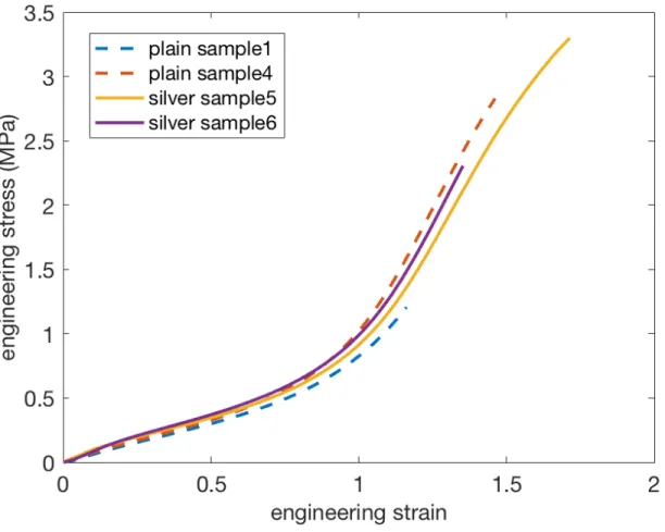
Figure 3.12 –Stress-strain relationship for PDMS membrane . . . 50
Figure 3.13 –Shape of the membrane as it deforms . . . 51
Figure 3.14 –Stress test of membrane . . . 52
Figure 3.15 –Computed field of view for optical configurations . . . 57
Figure 3.16 –Computed properties for different eye reliefs at specified focal depths . . . 58
Figure 3.17 –Computed properties for different display distances at specified focal depths . . . . 59
Figure 4.1 – System overview . . . 61
Figure 4.2 – First prototype field of view (FOV) . . . 63
Figure 4.3 – First prototype system overview . . . 64
Figure 4.4 – First prototype display . . . 65
Figure 4.5 – First prototype vacuum system . . . 66
Figure 4.6 – First prototype control electronics . . . 67
Figure 4.7 – First prototype point spread photograph . . . 69
Figure 4.8 – First prototype displaying teapots in hand at several depths . . . 71
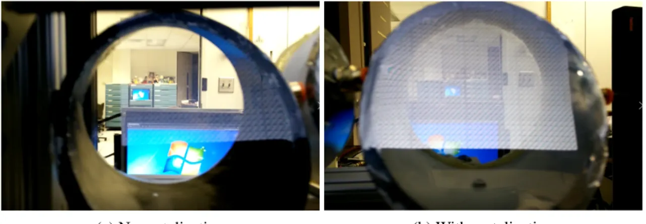
Figure 4.9 – View through second display prototype . . . 71
Figure 4.10 –Second prototype display . . . 72
Figure 4.11 –Second prototype system overview . . . 73
Figure 4.12 –Close up view of rendered blur . . . 74
Figure 4.13 –Membrane control circuit in second prototype . . . 76
Figure 4.14 –Second prototype vacuum system . . . 77
Figure 4.15 –Field of view of both prototype displays . . . 78
Figure 4.16 –Second prototype modulation transfer function . . . 80
Figure 5.1 – Calculating the distance of fixation using trigonometric methods . . . 85
Figure 6.1 – Monocular acuity study experiment configuration . . . 94
Figure 6.2 – Virtual and real co-located example stimuli . . . 94
Figure 6.3 – Virtual and real co-located task performance . . . 96
Figure 6.4 – Over-driving focus experiment configuration . . . 98
Figure 6.5 – View of monocular over-driving focus experiment display . . . 99
Figure 6.6 – Over-driving focus experimental procedure . . . 100
Figure 6.7 – Over-driving focus experiment results . . . 102
Figure 6.8 – Over-driving accommodation and vergence configuration . . . 104
Figure 6.9 – View of binocular vergence and accommodation over-driving experiment display . . . 105
Figure 6.10 –Over-driving accommodation and vergence experimental procedure . . . 107
Figure 6.11 –Over-driving focus and vergence experiment latency . . . 109
Figure 6.12 –Over-driving focus and vergence experiment results . . . 110
Figure 6.13 –Over-driving accommodation and vergence with saccade experimental procedure . . . 111
Figure 6.14 –Over-driving focus and vergence with saccade experiment latency . . . 113
Figure 6.15 –Over-driving focus and vergence with saccade experiment results . . . 114
LIST OF ABBREVIATIONS
2D Two-Dimensional
3D Three-Dimensional
AR Augmented Reality
CFF Critical Flicker Fusion
CIE International Commission on Illumination cpd Cycles per Degree
DC Direct Current
D Diopter
DMD Digital Micromirror Display
DMMD Deformable Mirror Membrane Device DOF Depth of Field or Depth of Focus EOG Electrooculography
FDM Fused Deposition Modeling FOV Field of View
fps Frames per Second
FWHM Full Width at Half Maximum HMD Head-Mounted Display HVS Human Visual System IPD Interpupillary Distance IR Infrared Radiation IROG Infrared Oculography LCD Liquid Crystal Display LED Light-Emitting Diode
MEMS Micro-Electromechanical System
ML Machine Learning
NED Near-Eye Display OST Optical See-through
PC Personal Computer
PDMS Polydimethylsiloxane PET Polyethylene Terephthalate PFA Panum’s Fusion Area
PID Proportional Integral Derivative ppi Pixels per Inch
PVC Polyvinyl Chloride
REGT Remote Eye Gaze Trackers rpm Revolutions per Minute
Si Silicon
SLA Stereolithography Apparatus SLM Spatial Light Modulator SSC Scleral Search Coils TFT Thin Film Transistor
UNC-CH University of North Carolina at Chapel Hill USB Universal Serial Bus
VAC Vergence–Accommodation Conflict VOG Video Oculography
VR Virtual Reality VST Video See-through
CHAPTER 1: INTRODUCTION
With the advent of the modern computing era, as computers have developed from mechan-ical machines, through mainframes and personal computers, to our modern pocket-sized and internet-connected devices, there has been an accompanying progression in the methods of human-computer interaction. In the early days of modern computing, information transfer was limited to computer-prioritized batch interfaces such as paper tape, punch cards, and line printers. Even command-line interfaces with keyboards and text displays, which greatly increased the ease of communication between human and machine, mostly favored the machine by using unintu-itve commands. As more computational power became available, an increasing amount could be spent on improving the human interfaces, leading to graphical user interfaces with mouses, styli, and graphical displays. In the last decade and a half, user-prioritized mobile touch interfaces with hand-held touch displays and conversational interfaces with voice and speaker have become commonplace.
1.1 Augmented Reality
Azuma (1997) defined AR as requiring three elements. It must (1) combine real and virtual content, (2) be interactive in real time, and (3) be spatially registered in three dimensions.
AR has the potential to drastically change our daily lives. An interface with full environmen-tal integration could present new data and experiences allowing seamless transitions between real and virtual. Commercial AR is expected to open a multitude of possibilities by bridging the gap between computer graphics and human vision – creating virtual content that is indistinguishable from the real world.
In the medical field, several works have been presented illustrating how AR may enhance sur-gical procedures and rehabilitation (Ilie et al., 2004). Industrial applications include simplifying complex factory part assembly and training (Henderson and Feiner, 2011). In the commercial sector, explorations in a user seeing their reflection wearing a virtual outfit or being directed to a restaurant in a unfamiliar locale have been described (Scholz and Smith, 2016; Narzt et al., 2006). AR can enable better communication via more natural face-to-face telepresence (Wang et al., 2014). Many look toward entertainment as one of the largest markets for AR with descriptions of children playing at home with their favorite virtual characters (Vera et al., 2011), or experiencing cinema in the real world around us (MacIntyre et al., 2001). In short, by altering the very reality we experience, AR is a transformative technology.
1.2 Enabling Technologies
computer and human, and while it is dependent upon the other technologies, it will be the sole topic of this work.
Several different categories of displays exist with different capabilities and hardware require-ments. In broad terms they can be divided into spatial AR (projector-based displays), hand-held displays, video see-through (VST) near-eye displays (NEDs), and optical see-through (OST) NEDs. For spatial AR, the light engine is a projector not co-located with the user, which illumi-nates real-world objects. Common examples are sandtables and robotic avatars (Lincoln et al., 2011). Hand-held displays are the most common form of augmented reality available today. With phone or tablet applications such as Ikea Place1and Pokémon Go2, millions of users can experi-ence augmented reality with the devices they carry around every day (Scholz and Smith, 2016). With the recent resurgence of commerical VR devices, a simple way to extend them for AR appli-cations is to provide a VST component from a head-mounted camera. Commercial devices such as the Vive Pro3and Windows MR4headsets provide this additional functionality. The advantage of OST NEDs is in providing unobstructed views of the real world in a non-encumbering, hands-free manner. However, the difficulties in designing a device capable of combining real-world light with the light of virtual imagery in an acceptable manner will be described in section 2.3.
1.3 Near-Eye Displays for Augmented Reality
Current available commercial OST AR NEDs like Microsoft Hololens5and Magic Leap One6 are successful in overlaying high quality virtual images onto the real world, but have limitations in terms of available field of view (FOV) and resolution. The Hololens presents stereoscopic imagery without correct focal cues, while the Magic Leap One has begun to address the lack of
1https://highlights.ikea.com/2017/ikea-place/
2https://www.pokemongo.com/en-us/
3https://www.vive.com/us/product/vive-pro/
4https://www.microsoft.com/en-us/windows/windows-mixed-reality
5https://www.microsoft.com/en-us/hololens
focal cues by providing a display with two focal planes. While an improvement, two focal planes are still far from what the real world provides, and the device has a similarly limited FOV. Fig-ure 1.1 depicts a scenario that illustrates the need for focus support in AR NEDs.
The need for a wide FOV has been demonstrated by many research studies (Arthur, 2000), but the following simple logic exercise presents a compelling argument. Visual augmentations can have many purposes, among which are calling attention to and providing additional infor-mation about real world objects. If a display is capable of only presenting augmentations in a small field — even if the real world is much more widely visible — it becomes difficult to call attention to objects outside the current FOV. It would require the user to turn their head so that an object falls in the view frustum of the display for any attention-calling and detail-providing augmentation to appear, and much augmented information may go unviewed. While additional interface cues may be provided indicating off-screen content (Roberts et al., 2013), in a densely annotated environment these cues just become additional noise and are insufficient to the task. A wide FOV enables attention-calling augmentations in the periphery of the visual field to perform their task as designed.
This dissertation presents a solution to both of these problems: deformable beamsplitters, a new type of dynamic optical element. Traditional beamsplitters, or half-silvered mirrors, have been used in many AR applications from NEDs to Pepper’s ghost (Groth, 2007). Deformable beamsplitters combine a traditional deformable membrane mirror and a beamsplitter into a single element, allowing reflected light to be manipulated by the deforming membrane mirror, while transmitted light remains unchanged. Displays using deformable beamsplitters are more practical and inexpensive than comparable focus providing NEDs.
1.4 Thesis Statement
better able than previous designs to integrate virtual imagery with the real world in measurable, perceptually advantageous ways.
1.5 Contributions
The primary contribution of this dissertation is the description and characterization of a new dynamic optical element, the deformable beamsplitter, which can adjust the focus of reflected light while not affecting transmitted light. Its application to NEDs is discussed and two proto-types which provide wide FOV and extended focal range in a small, light-weight formfactor. The potential for driving these NEDs through the use of eye tracking is examined and determined to not be feasible with currently available eye tracking solutions. A user study validates the capa-bility of our prototypes in improving accuracy during mixed reality tasks. Additionally, potential enhancements to human perception enabled by the new optical element are explored.
1.6 Structure
CHAPTER 2: BACKGROUND
In his assessment of the state of VR in 1999, Fred Brooks paraphrased a lecture from 1965 given by Ivan Sutherland (Sutherland, 1965):
Don’t think of that thing as ascreen, think of it as awindow, a window through which one looks into avirtual world. The challenge to computer graphics is to make that virtual world look real, sound real, move and respond to interaction in real time, and even feel real. (Brooks, 1999)
If we are to take Sutherland literally, then our goal for making the virtual world look real is to calculate and recreate every property for all light that would pass from a virtual world through our display window and into the pupils of the eyes. The light passing through a classical window can be deconstructed into a set of rays of light. A single ray of lightrcan be represented as
r= (x,y,z,t,θ,φ,λ,ψ,χ) (2.1)
wherex,y, andzare the coordinates of the emission point,tis the emission time,θ andφ are the
emission angle,λ is the wavelength of the light, andψ andχ are the polarization state.
Luckily, recreating all of these properties is not required. The HVS is not sensitive to the sum properties of light for the entire set of rays, as can be seen by examining a simple case. While in certain conditions, the human eye can detect the polarization state of light,ψ andχ, generally
NEDs (sections 2.1 and 2.2), I will review considerations required in designing NEDs (section 2.3), and I will review previous related display works (section 2.4).
2.1 Monocular Human Visual System
The human eye is a complex system for collecting, focusing, and sensing a narrow band of the electro-magnetic spectrum. The clear cornea and aqueous humor act as the first optical sur-face collecting the light through the pupil, which acts as an aperture stop, and relaying it to the crystalline lens. The crystalline lens has an adjustable curvature which adds additional focusing power based on the tension of the ciliary muscles. The light then passes through the vitreous humor and hits the retina, which contains a layer of two types of sensor cells that are sensitive to light. The retina has several regions which are defined by different characteristics in the dis-tribution of the two types of sensor cells. A region in the center of the field of vision, called the fovea, contains the highest density of retinal cones and is the area of highest visual acuity. Two additional features visible from outside the eye are the iris, which controls the size of the pupil, and the sclera, an opaque white protective layer of the eye. An illustration detailing the basic parts of the eye can be seen in Figure 2.1.
2.1.1 Angular Resolution
Human visual acuity is limited by many factors including sensor cell distribution, pupil diffraction, lens aberrations, and contrast of stimulus. An illustration of the spatial contrast sensi-tivity function can be seen in Figure 2.2. The consensus of studies explained in Weymouth (1958) show that the maximum angular resolution in the central fovea for human with 20/20 acuity to be about 0°3000 of arc or 60 cycles per degree(cpd).
Figure 2.1: Anatomy of the human eye. Used with permission (staff, 2014).
Cones
Rods
150 000
100 000
50 000
0
-60° -40° -20° 0°
20° 40° 60° 80°
Angle from fovea
Number of
recept
ors per mm²
Fovea
Blind spot
Figure 2.3: Density of rod (dotted line) and cone (solid line) photoreceptors along a line passing through the fovea and the blind spot of a human eye vs the angle measured from the fovea. Used with permission (Cmglee, 2013).
2.1.2 Field of View
A typical human monocular visual field extends 60° nasally limited by the nose, 60° superi-orly limited by the eyebrow, 100° temporally limited by the pupil and 70° inferisuperi-orly limited by the cheek (Savino and Danesh-Meyer, 2012). This means a total monocular FOV of 160° horizon-tal and 130° vertical, but a polar plot more fully expresses the average FOV as seen in Figure 2.4 and Figure 2.5. When eye motion is considered, an additional 50° may become visible as the eye rotates toward the temple (Howard and Rogers, 2008).
2.1.3 Temporal Resolution
10° 20° 30° 40° 50° 60° 70° 80° 90° Brow
Nose
Cheek
Human FOV
Figure 2.4: Field of view for the average human right eye, as measured from directly in front of the head. Views are blocked by the brow above, nose to the left, and cheek below (Fuchs, 1899).
10° 20° 30° 40° 50° 60° 70° 80° 90°
Left Eye Right Eye
based on intensity or visual solid angle of the stimulus, and the visual field eccentricity or state of fatigue in the user. The standard range for CFF is 50 Hz to 90 Hz (Landis, 1953; Farrell et al., 1987; Liu et al., 2014).
2.1.4 Eye Movements
There are four major kinds of eye movement: saccades, smooth pursuit, vergence, and vestibulo– ocular movements. Saccadesencompass both the large motions of looking around a room and the small motions of reading a book, and both eyes always rotate in the same direction. They can be voluntarily initiated, but occur reflexively, lasting between 15 ms and 100 ms, and incur a strongly suppressed visibility, known assaccadic suppressionorsaccadic omission, during and shortly after the motion. Smooth pursuitis a tracking mechanism for following a moving stimulus and maintaining its location on the fovea. Such tracking can successfully be performed up to a cer-tain velocity of moving objects, typically less than 80 °/s, and in most people requires a moving stimulus.Vergencemovements align the two eyes as the fixation point changes in depth, and are characterized by the two eyes moving in opposite directions. Their speed and characteristics are described further in section 2.2. The last classification of eye movements isvestibulo–ocular, which stabilize the image on the retina as head motion occurs. This compensatory reflex allows for stable percepts by offsetting the head motion with eye motion (Purves et al., 2001).
It should be noted that each of these motions has an effect on the temporal resolution of the eye. For example, when motion is involved studies have shown that flicker is perceived at fre-quencies higher than the CFF (Watson, 2013).
2.1.5 Focus and Blur
Figure 2.6: Eye sensitivity functionV(λ)and luminous efficacy measured in lumens per watt of
optical power across the light spectrum.V(λ)is maximum at 555 nm. From Schubert (2003)
Blur is also a very important perceptual depth cue (Zannoli et al., 2016); an accommodation-supporting, dynamic-focus display incapable of displaying multiple depths simultaneously needs to render appropriate synthetic blur on virtual objects that are at focal distances different than the current displayed depth. Recent studies show that computational blur that takes into account the chromatic aberrations of eye, dubbed Chroma-blur (Cholewiak et al., 2017), can improve perceived quality of synthetic imagery.
2.1.6 Wavelength
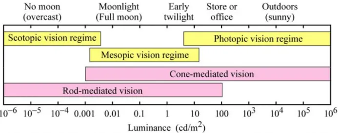
wave-Figure 2.7: Approximate ranges of vision regimes and receptor regimes across the dynamic range of the human eye. From Schubert (2003).
lengths is described by the CIE in 1978 and can be seen in figure 2.6. The function has a maxi-mum at 555 nm in the green range, and falls off to the red and violet (Schubert, 2003).
2.1.7 Dynamic Range
Due to the different sensitivities of the cone and rod cells, the human eye has a wide range of illumination sensitivity which can be broken down into 3 ranges. Photopicvision occurs at ranges of high ambient illumination and is mediated by the cones. Scotopicvision happens at low ambient illumination ranges when vision is mediated by the rods, a primary characteristic of which is loss of color sensitivity. Mesopicvision occurs at the illuminace levels between the photopic and scotopic ranges when vision is mediated by both cones and rods (Schubert, 2003).
2.1.8 Polarization
Polarization, having minimal impact on human perception, is generally ignored with respect to presenting it correctly in displays. It is often used by the display itself as a means of control-ling and manipulating the light transfer and conditioning through the optical system. To the best of my knowledge, no studies have explored the effects of presenting incorrect polarization cues to a viewer in virtual or augmented environments.
2.2 Binocular Human Visual System
While the visual responses in the monocular eye are easily linked to physiological elements, the mechanism for combining the images from two eyes into a single percept, referred to as binocular fusion, is more elusive. Many mechanisms, including the vergence and accommoda-tion of the eyes, come into play when fusing the two images. When these mechanisms fail, the possible outcomes are referred to asbinocular rivalry. Rivalry encompasses bothsuppression, where the brain suppresses the view from one of the eyes either spatially or time varying, and diplopia, where both views are visible simultaneously — commonly called double vision. For a comfortable AR experience, an AR display needs to provide appropriate perceptual cues so that proper vision may be maintained.
2.2.1 Vergence–Accommodation Conflict
2.2.2 Panum’s Fusion Area
For a given object depth, there exists a range of eye vergence where binocular fusion will occur. This range is known asPanum’s fusion area(PFA) and it is depicted in Figure 2.8 top. It is not in the scope of this work to fully describe the topic; the interested reader is directed to the work of Schor et al. (1984) and Ogle (1932). Any vergence error larger than 0°150to 0°300will cause a failure in binocular fusion resulting in either suppression or diplopia, while smaller errors will lead to a loss in stereoacuity (Hoffman et al., 2008).
When presenting virtual stimuli, any inconsistent error in horizontal position of the separate eye’s virtual images will result in incorrect depth perception rather than failure in binocular fu-sion as the user adapts their vergence to the displayed stimulus. However if unmatched intra-eye distortion occurs beyond the range of PFA, binocular single vision is lost.
2.2.3 Depth of Field / Depth of Focus
The perceptual sensitivity to lack of focus is characterized by the eyedepth of fieldordepth of focus(DOF), which denotes the maximum range of retinal defocus that does not cause perceiv-able blur. For a given focal depth, there exists a range of eye accommodations where defocus blur is imperceptible. Many studies have been performed in an attempt to characterize the size of the DOF for the human eye and the factors which affect it.
In the most crude of simplifications, many display makers simplify this to a single value of
0 1 2 3 4 0
1 2 3 4
Vergence Distance (d)
F
ocal
Distance
(d)
DOF PFA Natural
0 1 2 3 4
0 1 2 3 4
Vergence Distance (d)
F
ocal
Distance
(d)
ZCSBV ZOC Natural
relatively near retinal periphery of 5°, it increases to 2.5 D. DOF saturates at the level of 6 D to 7 D for eccentricities larger than 30°.
2.2.4 Zone of Clear Single Binocular Vision
For any combination of accommodation and vergence depths, there is a zone where binocular fusion and proper focus can occur. This is known as thezone of clear single binocular vision (ZCSBV) and is depicted in 2.8 bottom (Hoffman et al., 2008; Shibata et al., 2011; Fry, 1939). While the size of the ZCSBV varies on an individual basis, generally the boundaries are±1.5 D to 2 D from the natural viewing case.
2.2.5 Zone of Comfort
While it is possible to fuse images inside the ZCSBV, certain combinations of accommoda-tion and vergence put undue stress on the visual system. Any time spent in these regions will accumulate eye strain leading to visual discomfort and fatigue. However, a subset of the ZCSBV exists where it is safe to remain for extended periods without accumulating strain; this region is called thezone of comfort(ZOC) which is about one-third the size of the ZCSBV (Shibata et al., 2011; Hoffman et al., 2008; Percival, 1910; Sheard, 1934).
2.2.6 Accuracy of Vergence and Accommodation
2.2.7 Speed of Vergence and Accommodation
An initial reaction time, or latency, in the range of 150 ms to 200 ms for vergence and 300 ms to 500 ms for accommodation has typically been observed before the actual change is initiated (Campbell and Westheimer, 1960; Morgan, 1968; Phillips et al., 1972; Schor, 1992; Heron et al., 2001; Bharadwaj and Schor, 2005). While Phillips et al. (1972) have observed latencies as short as 200 ms for accommodation, the probability of their occurrence is very low. They hypothesize that such short latencies can be explained by coincidence or confusion of some subjects who have not carefully followed the experiment protocol.
Response time is dependent on the distance traveled and the direction of the fixation change, either far to near, meaning accommodation and convergence, or near to far, meaning disaccom-modation and divergence. The duration of convergence and divergence are typically within 200 ms to 800 ms and lens accommodation is in the range of 500 ms to 800 ms (Campbell and Westheimer, 1960; Phillips et al., 1972; Bharadwaj and Schor, 2005; Heron et al., 2001; Morgan, 1968; Schor, 1992; Erkelens et al., 1989).
The velocity of accommodation is a useful measure of the lens accommodation dynamics. Bharadwaj and Schor (2005) observed a smooth increase in velocity to its peak value and then its slightly slower reduction to a steady state. As accommodation magnitude increased, so did the peak velocity – with a maximum value of around 10 D/s. Kasthurirangan et al. (2003) observed a similar average peak velocity for the lens accommodation, but a high variance can be observed in their data. Also, for disaccommodation, peak velocities over 20 D/s have been measured for the large accommodation magnitudes of 4 D to 5 D.
Erkelens et al. (1989) report a maximum vergence velocity of convergence of 120 °/s to 190 °/s and divergence of 160 °/s to 180 °/s for 32° vergence amplitudes. Mean vergence ve-locities for the same amplitudes were reported as 38 °/s to 59 °/s for convergence and 45 °/s to 53 °/s for divergence.
re-sponse duration of vergence is also decreased. Schor et al. (1999) report that the period of latency for accommodation is reduced by 13 % and the velocity of accommodation response increased by 27 % when a simultaneous saccade is performed. Enright (1984) reports that vergence is sped up by between 30 % and 40 % when synchronous saccadic motion accompanies the depth change.
All expressed values for the dynamics of vergence and accommodation are for the case when a subject is presented with an unanticipated stimulus. However, the case when voluntary depth change occurs, as with the user-driven fixation in varifocal optical see-through (OST) AR dis-plays, has not fully been studied. Some discussion on the topic by Ciuffreda and Kruger (1988) indicates that under the user-driven condition an estimated amount of accommodation, which could be used to resolve details, would occur before any retinal-blur information is received. This preprogramming would make the visual scanning process more efficient. Kruger and Pola (1986) suggest that the natural mode of the accommodation system is anticipation, while Kruger and Pola (1987) show that accommodative prediction is a key component in tracking regularly ap-proaching and receding objects. These discussions indicate that for voluntary depth changes, the latent period would be drastically reduced, if not eliminated entirely, and pre-accommodation may occur, such that the response time would happen partially before the fixation change is ini-tiated. Unfortunately, until further studies are made on user-driven changes to fixation depth, we must base our requirements on reported values, and therefore use the stimulus-driven results described above.
2.3 Considerations in Developing Near-Eye Displays
Several limitations in reaching these goals are related to the underlying technologies such as the interplay between battery size and weight, heat dissipation, run time, and computational power, while other considerations arise from trade-offs between features and capabilities of the device design. If not considered carefully, the design may prevent users from having comfortable, long-lasting experiences. In this section, I will focus on device design considerations with bear-ing on the generation of the visual imagery while attemptbear-ing to discuss the applicable principles and choices required when designing a head-mounted display (HMD).
There are a few attributes which should be minimized as much as possible. Those include: • Size – the physical dimensions of the device. Since these displays are head-mounted,
smaller is better.
• Weight – the physical weight of the device. The mass mounted on the head needs to not only be minimized, but consideration should be given to its distribution.
• Computational Power – the amount of computation dedicated to forming the optical image. Primary rendering of the scene is not included. A simple example is the computation to generate the binary frames from a DMD light engine which are time-integrated to form higher contrast and full-color images.
• Operational Power – the amount of power required to generate and transport the photons to the eye. For mobile devices which operate from battery power, maintaining a low power draw is essential for extended usage.
• Heat Generation – the amount of heat generated by the optical system. For devices mounted to the head, minimizing heat generation is very important.
There are many attributes which should be increased as close to the human perceptual bound-aries described in Sections 2.1 and 2.2 as possible. Those include:
extent, but separate width and height values are sometimes given. As shown by Arthur (2000), a limited FOV degrades task performance among other effects.
• Angular Resolution – the number of cycles per degree the display is capable of displaying; measured by modulation transfer function (MTF), a measurement of contrast per spatial frequency. Consideration should be given to the resolution required by the applications for the display; in particular the presentation of text, as the correct method of font hinting in HMDs is an open problem.
• Eye Box – the area within which a view-able image is generated by the display; measured in millimeters of diameter. The light from the display must be able to enter the pupil of any user as they change gaze direction, either through adjustment or size. The range of both interpupillary distance (IPD) and eye motion should be considered.
• Focus Range – the range of depths where images may appear in sharp focus – can be time-varying; measured as the difference of diopters of optical power from near to far. To mit-igate VAC and ensure images stay within the ZCSBV, it is necessary to provide accurate depth cues for the rendered synthetic imagery, which either requires recreating the entire light field accurately, or actively changing the focus of the virtual image to optically regis-ter it to the appropriate real-world depth.
• Real-world Transmittance – the percentage of real-world light transmitted through the display; measured as a percentage of transmittance. For VST systems latency should also be considered.
• Occlusion Resolution – the number of distinct volumetric real-world regions which can be dynamically blocked from transmitting light. For displays without occlusion, this is zero.
• Luminance – the average luminous intensity per unit area of light emitted from the display; measured in candela per square meter.
• Contrast Ratio – the ratio of luminance for the brightest white to that of the darkest black simultaneously displayed; measured as a ratio.
• Dynamic Range – the range of luminance for the brightest white to that of the darkest black the display is capable of displaying given time for adaptation; measured as a ratio.
• Color Gamut – the set of colors the display can accurately reproduce; measured as a per-centage of coverage of CIE 1931.
While many designs will have trade-offs specific to the optical or computational nature of the display, such as the computational power/frame rate/focal range fidelity trade-off of light field displays, here I discuss trade-offs which are mostly global to all NEDs.
2.3.1 Étendue or Throughput
Étendue, or throughput, is a measure of the flux gathering capability of an optical system. When étendueε is combined multiplicitively with the radianceL(intensity of the light) it gives
the total powerΦof the light passing through the system as defined here for a perfectly uniform
and Lambertian source:
For a lossless optical system, étendue is invariant; the light entering the system is equivalent to the light leaving the system. In a display, étendue is the product of the area of the imaging sourceAiand the solid angle of light that enters the optical systemΩi, which is equivalent to the
product of the size of the eye boxAeand the FOVΩeas described by the following equation:
ε =AiΩi=AeΩe (2.3)
Equation 2.3 shows the direct trade-off between FOV and eye box size. If we seek to increase both FOV and eye box, a larger imaging source is required meaning the size of the device will likely increase. So there is an interplay between the display size, FOV, and eye box. Additionally, for a given imaging source, if we increase the FOV by decreasing the eye box, the resolution of the output image will be spread across a larger angle meaning a decrease in the angular resolu-tion.
One alternative often used to get around the limitations of étendue is pupil expansion. For pupil expansion, the radiance of the image source is split into multiple optical paths with separate exit pupils or eye boxes. In this manner, the luminance of the image is reduced, but with multiple eye boxes produced, the effective eye box size is increased.
2.3.2 Focal Range Trade-off
be used to decrease the overall size of the display, but come at a large cost in the computation required for displaying the imagery.
2.3.3 Real-world Transmission
In AR, the manner and quality that the real world is conveyed to the eye is important to con-sider. OST has the advantage of letting the light from the real world, in its full complexity, pass directly to the user; however some amount of attenuation and/or blockage is likely to occur. If the display is meant for outdoor use, attenuation of the bright sunlight may be desired so that the lower luminance of the display may be perceived; however indoors, the same attenuation would darken the view undesirably. Ideally the attenuation will be at a level where virtual content may be overlaid on either bright or dark backgrounds with enough contrast to provide clear viewing. The contrast of virtual content could be enhanced with an occlusion capable display, but such displays exhibit additional problems with bulk, correct occlusion focus, and occlusion latency.
2.3.4 Visual Quality
The luminance, contrast, and dynamic range of the display are co-dependent; with a greater luminance, better contrast and dynamic range usually follow, so providing a greater maximum luminace is desirable. Additionally, reducing noise, as measured in peak signal-to-noise ratio, in the final image and maintaining a high MTF are important to the final image quality.
2.4 Prior Work
stereoscope capable of recreating motion using rotating disks or wheels were developed, it was the development of projected motion pictures that enabled Emile Reynaud in 1889 to create the first stereoscope capable of displaying motion sequences of arbitrary length (Zone, 2007).
The development of electronic image capture, transmission, and reconstruction — collec-tively called television — enabled live-streaming video via cameras. In 1961, Philco Corporation demonstrated Headsight, the first system to employ both a real-time video stream and head mo-tion tracking which was linked to a momo-tion-controlled closed-circuit camera for natural views of a remote location (Kiyokawa, 2007a). The next major step for NEDs came after the development of modern computers, which enabled interactive presentation of 3D data as shown by Sutherland (1968). Despite the display not providing either stereoscopic or focal cues, it showed the poten-tial of presenting motion-tracked computer-generated imagery on an HMD. Around the same time period, Thomas Furness III and his Visual Display Systems Branch in the United States Air Force were developing their own helmet-mounted displays for flight control and pilot training including binocular, motion-tracked, real-time systems (Furness, 1986).
From these foundations, HMDs continued to evolve from the research lab to industrial tools and eventually from experiential arcades to consumer products. Researchers have proposed sev-eral classical optical designs (Kiyokawa, 2007b; Arthur, 2000; Nagahara et al., 2006; Sisodia et al., 2005) to address improving FOV. As demonstrated by Ilie et al. (2004) and Benko et al. (2015), combining an NED with projections promises a larger FOV, but it introduces new practi-cal challenges. Throughout this refinement process, while attributes such as form-factor, weight, and FOV were improved, it wasn’t until relatively recently when increasing the focal depth range was widely addressed as a means for solving VAC.
Supporting accommodative cues is known to cause major complications in an NED’s optical design. Several different techniques have been shown effective in providing more than a single fo-cal depth. Always-in-focus and extended-focus methodologies such as Maxwellian View displays discussed in section 2.4.1 are advantageous because user state does not need to be accounted for. They can imitate defocus blur during image generation, and may provide large FOV with a small form-factor, but are typically limited in angular resolution due to diffraction of the pupil. Virtual retinal displays detailed in section 2.4.2, can provide correct focal cues through beam shaping, but face a difficult trade-off with resolution and time. Multifocal approaches presented in section 2.4.3 enable correct focal cues at the depths of the virtual images, but suffer from loss of resolution when interpolating to distances between the focal planes and a limited FOV. Vari-focal techniques examined in section 2.4.4 provide high angular resolution and accommodative cues, but historically suffer from limited FOV. Recent works have improved the FOV, making varifocal a good optical choice for reducing VAC while being computationally and optically sim-pler than other techniques. Computational methodologies such as light fields characterized in section 2.4.5 can provide accommodative cues while enabling wide FOV. However, light field displays demand a significant amount of image formation computation and are limited in angu-lar resolution. Displays based on computer generated holography summarized in section 2.4.6 are capable of providing per-pixel focal depth, but due to current spatial light modulator (SLM) technology, have a very constrained étendue.
2.4.1 Maxwellian View Displays
The procedure of projecting an illuminating source on the eye’s pupil instead of viewing it directly is called Maxwellian viewing (Westheimer, 1966). Displays that are designed to follow this principle, where the screen plane is the optical conjugate of the retina and the illumination source is the conjugate of the eye’s pupil plane, are called Maxwellian view displays. Since the source is imaged on the eye’s pupil, and the image is formed on the retina, the result is typically
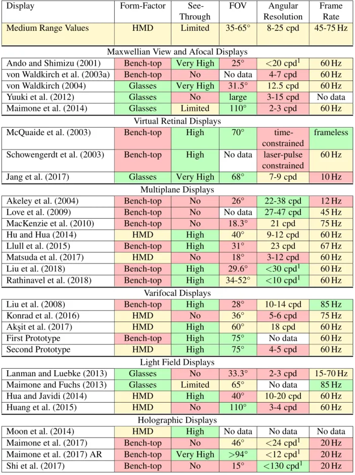
Table 2.1: Comparison of Near-Eye Displays with Accommodative Cues Part 1
Display Form-Factor
See-Through
FOV Angular
Resolution
Frame Rate
Medium Range Values HMD Limited 35-65° 8-25 cpd 45-75 Hz
Maxwellian View and Afocal Displays
Ando and Shimizu (2001) Bench-top Very High 25° <20 cpd1 60 Hz von Waldkirch et al. (2003a) Bench-top No No data 4-7 cpd 60 Hz von Waldkirch (2004) Glasses Very High 31.5° 12.5 cpd 60 Hz
Yuuki et al. (2012) Glasses No large 3-15 cpd No data
Maimone et al. (2014) Glasses Limited 110° 2-3 cpd 60 Hz
Virtual Retinal Displays
McQuaide et al. (2003) Bench-top High 70°
time-constrained
frameless Schowengerdt et al. (2003) Bench-top High No data laser-pulse
constrained
60 Hz
Jang et al. (2017) Glasses Very High 68° 7-9 cpd 10 Hz
Multiplane Displays
Akeley et al. (2004) Bench-top No 26° 22-38 cpd 12 Hz
Love et al. (2009) Bench-top No No data 27-47 cpd 45 Hz
MacKenzie et al. (2010) Bench-top No 18.3° 21 cpd 75 Hz
Hu and Hua (2014) HMD High 40° 9-12 cpd 60 Hz
Llull et al. (2015) Bench-top High 31° 23 cpd 67 Hz
Matsuda et al. (2017) HMD No 18° 3-12 cpd 60 Hz
Liu et al. (2018) Bench-top High 29.6° <30 cpd1 60 Hz
Rathinavel et al. (2018) Bench-top High 34-52° <10 cpd1 60 Hz Varifocal Displays
Liu et al. (2008) Bench-top High 28° 10-14 cpd 85 Hz
Konrad et al. (2016) HMD No 36° 5-6 cpd 75 Hz
Ak¸sit et al. (2017) HMD High 60° 18 cpd 60 Hz
First Prototype Bench-top High 75° No data 60 Hz
Second Prototype HMD High 75° 4-5 cpd 60 Hz
Light Field Displays
Lanman and Luebke (2013) Glasses No 33.3° 2-3 cpd 15-70 Hz
Maimone and Fuchs (2013) Glasses Limited 65° No data 85 Hz
Hua and Javidi (2014) HMD High 40° 10-20 cpd 60 Hz
Huang et al. (2015) HMD No 110° 3-4 cpd 60 Hz
Holographic Displays
Moon et al. (2014) HMD High No data No data No data
Maimone et al. (2017) Bench-top No 46° <24 cpd1 20 Hz
Maimone et al. (2017) AR Bench-top Very High >94° <12 cpd1 20 Hz
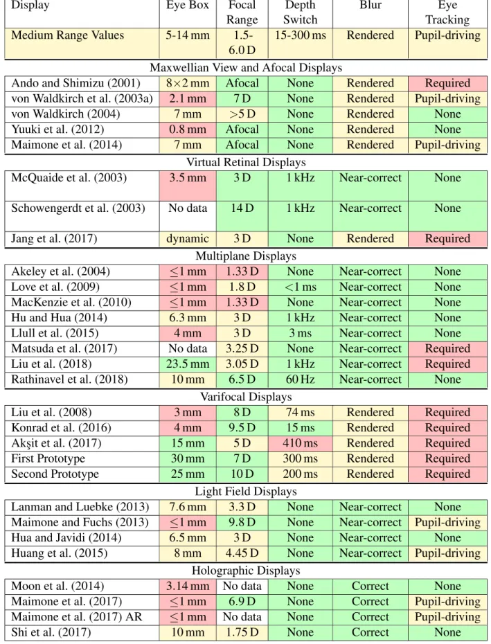
Table 2.2: Comparison of Near-Eye Displays with Accommodative Cues Part 2
Display Eye Box Focal
Range
Depth Switch
Blur Eye
Tracking Medium Range Values 5-14 mm
1.5-6.0 D
15-300 ms Rendered Pupil-driving Maxwellian View and Afocal Displays
Ando and Shimizu (2001) 8×2 mm Afocal None Rendered Required von Waldkirch et al. (2003a) 2.1 mm 7 D None Rendered Pupil-driving
von Waldkirch (2004) 7 mm >5 D None Rendered None
Yuuki et al. (2012) 0.8 mm Afocal None Rendered None
Maimone et al. (2014) 7 mm Afocal None Rendered Pupil-driving
Virtual Retinal Displays
McQuaide et al. (2003) 3.5 mm 3 D 1 kHz Near-correct None
Schowengerdt et al. (2003) No data 14 D 1 kHz Near-correct None
Jang et al. (2017) dynamic 3 D None Rendered Required
Multiplane Displays
Akeley et al. (2004) ≤1 mm 1.33 D None Near-correct None
Love et al. (2009) ≤1 mm 1.8 D <1 ms Near-correct None MacKenzie et al. (2010) ≤1 mm 1.33 D None Near-correct None
Hu and Hua (2014) 6.3 mm 3 D 1 kHz Near-correct None
Llull et al. (2015) 4 mm 3 D 3 ms Near-correct None
Matsuda et al. (2017) No data 3.25 D None Near-correct Required Liu et al. (2018) 23.5 mm 3.05 D 1 kHz Near-correct Required Rathinavel et al. (2018) 10 mm 6.5 D 60 Hz Near-correct None
Varifocal Displays
Liu et al. (2008) 3 mm 8 D 74 ms Rendered Required
Konrad et al. (2016) 4 mm 9.5 D 15 ms Rendered Required
Ak¸sit et al. (2017) 15 mm 5 D 410 ms Rendered Required
First Prototype 30 mm 7 D 300 ms Rendered Required
Second Prototype 25 mm 10 D 200 ms Rendered Required
Light Field Displays
Lanman and Luebke (2013) 7.6 mm 3.3 D None Near-correct None Maimone and Fuchs (2013) ≤1 mm 9.8 D None Near-correct Pupil-driving
Hua and Javidi (2014) 6.5 mm 3 D None Near-correct None
Huang et al. (2015) 8 mm 4.45 D None Near-correct Pupil-driving Holographic Displays
Moon et al. (2014) 3.14 mm No data None Correct None
Maimone et al. (2017) ≤1 mm 6.9 D None Correct Pupil-driving Maimone et al. (2017) AR ≤1 mm No data None Correct Pupil-driving
Eye Pupil Screen
(a) direct viewing
Eye Pupil Eyepiece Screen Virtual Image
(b) direct viewing with lens
Eye Pupil Eyepiece SLM Condenser Light Source
(c) Maxwellian view (d) Ando and Shimizu (2001)
(f) Jang et al. (2017)
Eye Pupil Eyepiece 2 Axis Mirror Laser Raster Scan
(e) virtual retinal display
(h) Akeley et al. (2004)
Eye Pupil Beamsplitters Virtual Image Virtual Image
(g) multiplane
(j) Akşit et al. (2017) Eye Pupil Varifocal Lens Screen Virtual Image
(i) varifocal
Eye Pupil Micro-lens Array Screen Virtual Image
(k) light field
Eye Pupil Wavefront SLM Condenser Light Source
(m) holographic
(l) Lanman and Luebke (2013)
(n) Maimone et al. (2017)
always in focus. Several variants of the Maxwellian view displays have been proposed in the literature. Ando et al. (1998, 2000); Ando and Shimizu (2001) utilize both a holographic optical element and a digital micromirror display (DMD) (Hornbeck, 1997) to achieve retinal projection. While von Waldkirch et al. (2003b) use an LCD (liquid crystal display) and a set of collimation and projection lenses to achieve a quasi-accommodation-free Maxwellian viewing with high resolution. However, such displays have a very small depth of focus and eye box sizes. By us-ing an elliptical scannus-ing beam, von Waldkirch et al. (2003a) show that the depth of focus of a Maxwellian view retinal scanning display can be improved, whereas von Waldkirch et al. (2005) show an improved depth of focus by using an oscillating fluid lens in the retinal projection sys-tem. Yuuki et al. (2012) combined an LCD, pinhole array aperture mask, and micro-lens array to create a tessellated series of Maxwellian view displays capable of extended DOF.
Alternative always-in-focus mechanisms, related to Maxwellian view in that they project an image directly on the retina, also offer sharp imagery regardless of the viewer’s accommodation state. The “Pinlights" always-in-focus AR display (Maimone et al., 2014), by using a see-through sparse backlight mechanism behind an LCD, generates a tessellated series of retinal projectors capable of a wide FOV but limited in angular resolution.
2.4.2 Virtual Retinal Displays
mir-ror is controlled by the applied voltage, thereby controlling the focus of the displayed objects. Schowengerdt et al. (2003) showed an achievable accommodation range of 0 D to 14 D by the DMMD. Creating a volumetric display by application of deformable mirror membranes was at-tempted by Schowengerdt and Seibel (2006), where the membrane curvature was synchronized with per-frame swapping between two different images, thereby displaying the images at differ-ent depths simultaneously. The prototype demonstrated a depth range of 0 D to 16 D in a con-tiguous fashion. More recently, Jang et al. (2017) demonstrated a Maxwellian view style virtual retinal HMD with multiple projectors and a holographic optical element. While the Maxwellian view capability of the display extends the depth of field, the small eye box limitation is overcome by employing eye tracking and a moving eye box.
2.4.3 Multifocal Displays
Multifocal displays are capable of generating virtual images at more than one focal depth simultaneously. In the classical multiplane approach introduced by Rolland et al. (2000), virtual content displayed at one of the focal planes will have correct focus cues, but generating virtual content between the focal planes requires interpolation leading to less-correct focus and loss of resolution. These displays have large computational demands for decomposing and interpolat-ing the virtual content and complex optical hardware that doesn’t typically lead to a wearable form-factor. Much work has been done on improving scene decomposition and gaze-contingent multiplane capabilities (Mercier et al., 2017; Narain et al., 2015). There are two approaches for generating multiplane displays: optical path multiplexing and temporal multiplexing.
field of view. Mercier et al. (2017) developed a bench-top prototype combining a three-plane dis-play, gaze tracking, and focus tracking to demonstrate that despite multiplane displays showing near-correct focus cues without eye tracking, correct scene decomposition is dependent upon eye position. This means that eye tracking is required for displaying high quality images. Re-cently Rathinavel et al. (2018) detailed an extremely fast, time-multiplexed, multiplane display supporting 280 distinct depth planes. The density of depth planes is indistinguishable from a full volumetric display and shows the great potential of>20 kHz operating DMDs. However, the op-tical complexity in such approaches has thus far challenged their pracop-ticality in increasing FOV and decreasing form-factors.
As an alternative to multiplane displays, Matsuda et al. (2017) demonstrated a focal surface display, which uses a phase-only SLM to bend the focal plane of the image into a complex sur-face. These scene-optimized surfaces can improve the focal accuracy across simple scenes. They also propose combining multiple focal surface images into a multiplane focal surface display which would greatly reduce the number of focal planes required to accurately represent a scene. Akin to multiplane planes, Konrad et al. (2016) study an interesting scenario called monovision, where each eye is subjected to one focal depth, with one eye’s focus being near and the other eye’s focus being far. This approach leverages binocular single vision and suppression in an at-tempt at reducing VAC, with a loss of resolution. Detailed perceptual studies on monovision have also been conducted by Johnson et al. (2016a) and Koulieris et al. (2017) which found that not only did viewer comfort and visual performance not improve, but monovision displays do not drive accommodation to the simulated distance meaning they do not resolve VAC.
2.4.4 Varifocal Displays
used in the work of Liu et al. (2008), producing a small FOV but having a good accommodation range capable of switching depths within 74 ms. The study described in Konrad et al. (2016) also takes advantage of an electrically tunable lens system as relay optics and demonstrates a similarly small FOV VR prototype. Their solution switches depth from one extreme to another within 15 ms, and provides a better accommodation range. Ak¸sit et al. (2017) uses holographic optical elements for intermediate image formation before relaying the final image into the eye, offering a wearable form-factor with good FOV. All of the above mentioned varifocal display designs, suffer various drawbacks either in form-factor, depth-switching speed, or FOV.
Recent studies show evidence that supporting accommodative cues through a varifocal mecha-nism improves visual comfort (Johnson et al., 2016b) and user performance (Konrad et al., 2016). Just as with always-in-focus displays, objects not located at the current focal depth should have appropriate rendered blur to provide the appropriate focal cues.
2.4.5 Light Field Displays
Light field displays, in addition to the traditional color, intensity, and position, provide angu-lar control of the light generation leading to capabilities for correct parallax, stereoscopic view, and multi-view. With enough angular resolution they can also depict correct focus cues in an NED. Two approaches for creating light field displays have been presented thus far, integral and multi-layer.
advancements of free-form relay optics with a computational integral imaging methodology. Un-fortunately like with most designs the transition from VR to AR was accompanied by a loss in FOV. Ak¸sit et al. (2015) uses a pinhole mask in front of an LCD to create a light field at the eye and thus increase the apparent depth of field, but at the expense of resolution.
Multi-layer light fields use stacked SLMs with a single illumination source to add the angular control of the light. This approach works to increase the resolution above the integral approach, however it suffers from a loss of contrast as light must pass multiple SLMs and has a resolution limit from the compounding diffraction. Maimone and Fuchs (2013) detailed an AR near-eye multi-layer display with no reflective, refractive, or diffractive optical elements capable of oc-cluding the real world. While having an impressive focal range, and decent FOV, the display suffered from noise, low resolution, and poor contrast. More recently, Huang et al. (2015) demon-strated a prototype which employs two LCDs and a pair of classical magnifiers. This light field stereoscope was capable of producing a wide diagonal FOV and an improved image resolution.
2.4.6 Holographic Displays
2.5 Discussion
CHAPTER 3: DEFORMABLE BEAMSPLITTERS – A NEW OPTICAL ELEMENT
Setting out to design and produce a large-focal-range-providing AR NED, we examined the existing display categories. The simplicity of varifocal and time-multiplexed multiplane displays, it seemed, would provide a solid foundation from which to build. In order to improve on the ex-isting work, we set specific goals for having a wide FOV and good real-world transparency. Ad-ditionally, we wanted to maintain a fast focal change speed providing either a time-multiplexed multiplane display or, at slower speeds, a varifocal display capable of changing focus faster than the human eye. With these goals in mind, we sought an optical element that would meet our requirements:
1. fast focus changing, 2. wide FOV, and
3. good see-through characteristics.
3.1 Previous Work in Deformable Membrane Mirrors
Figure 3.1: Example photograph and diagram of a deformable membrane mirror display. Used with permission from Fuchs et al. (1982)
X z Y Pupil plane
Display
d
apertured
virtuald
eye reliefd
eyebox Membrane Tiltd
displayAnchor
point
p
sp
eFla
t m
irr
or
Far c
urv
atu
re
M
id
c
u
rv
at
u
re
N
ea
r c
ur
va
tu
re
N
ea
r
M
id
Fa
r
Display TiltFigure 3.2: A sketch showing our deformable beamsplitter display optical layout with parameters for the single eye case. An image on a display above the user’s eye reflects from our deformable membrane beamsplitter toward the eye. A virtual image can be created at a desired position in space by varying the curvature of our deformable membrane beamsplitter. Anomalous perspec-tive is demonstrated via the virtual cube size: display magnification increases as the distance increases.
Fuchs et al. (1982), and Mills et al. (1984). Later, McKay et al. (1999a), McKay et al. (1999b), and McKay et al. (2000) created a large 1.2 m membrane mirror capable of displaying 2D and 3D objects and enabling a telepresence system.
3.2 Developing Our Early Prototypes
would have the optical element we were looking for. In achieving transparency, two obstacles presented themselves: the opacity of the housing and driving mechanism, and the opacity of the mirror. By making the rear surface of the air-tight housing transparent using acrylic and moving the actuation mechanism away from the main chamber, we quickly overcame the first obstacle. Modifying the mirror was not so simple: we sought to replace the deformable mirror with a beamsplitter capable of deforming to the needed curvatures while combining the unaltered, trans-mitted real-world light with the focus-changing, reflected virtual images. After several material trials, we eventually found a material capable of the requisite deformations and having the re-flection and transmission characteristics desired. Combining both newly transparent portions, we had a new optical element that met all of our requirements which we named thedeformable beamsplitter.
In developing a usable prototype capable of generating high-quality images and controlling the membrane curvature at high speeds, we performed much experimentation in membrane mate-rials and housing construction. Most membranes described in the deformable membrane mirror literature consist of a metallized Mylar®, also known as polyethylene terephthalate (PET), film tensioned across a circular aperture. While optically-clear versions exist, at the time of investi-gation it was unclear if we could control the reflectance to transmission ratio. Eventually, when producing our in-house solution we developed a process of controlling the ratio, however we had already moved on to other materials and did not return to PET. Further investigation on using PET as a quickly oscillating beamsplitter would be a promising line of research.
3.2.1 Membrane
Figure 3.3: View of the poor image quality produced by the PVC film. Both image reflection (checkerboard) and image transmission (bright to dark edge) quality can be seen.
PDMS was advantageous because of its outstanding transparency in visible wavelengths, high elasticity, and providing in-lab fabrication for experimentation in formulation and membrane thickness. Metalization improves the reflection of the image as can be seen in Figure 3.5. The optical quality of both the reflection and transmission from a PDMS membrane can be seen in Figure 3.7.
Figure 3.4: Three-quarter front and rear views of an early prototype display using a PVC tube housing with a clear PVC film membrane.
(a) No metalization (b) With metalization
Figure 3.5: Comparing the difference in reflection intensity after membrane metalization on a PDMS membrane. In these images, the reflected image is not in focus; better quality reflections may be seen in later figures.
other hand, PDMS has numerous attractive material properties such as outstanding transparency in visible wavelengths, high elasticity, and excellent temperature stability. Our choice of a high elasticity material meant that deformations could occur without buckling, however the fast os-cillations needed for a multiplane approach were unachievable, so we focused on a varifocal approach. Inspired by these advantages, we created our own recipe for the task.

![Figure 2.8: Visualizations of Panum’s Fusion Area (PFA) compared with Depth of Field (DOF) [top] and the Zone of Clear Single Binocular Vision (ZCSBV) compared with the Zone of Comfort (ZOC) [bottom]](https://thumb-us.123doks.com/thumbv2/123dok_us/8327339.2208310/35.918.251.670.124.977/figure-visualizations-fusion-compared-binocular-vision-compared-comfort.webp)