Instruction manual
CyberSentry SEM software revision: 1.00GE publication code: 1601-9202-A2 (GEK-113634A)
CyberSentry
Security Event Manager
GE
Digital Energy
GE Digital Energy 650 Markland Street Markham, Ontario Canada L6C 0M1
Copyright © 2013 GE Multilin Inc. All rights reserved. CyberSentry SEM software revision 1.00.
CyberSentry, Digital Energy, Multilin, and GE Multilin are trademarks or registered trademarks of GE Multilin Inc.
The contents of this manual are the property of GE Multilin Inc. This documentation is furnished on license and may not be reproduced in whole or in part without the permission of GE Multilin. The manual is for informational use only and is subject to change without notice.
CyberSentry SEM Software
Table of contents
GLOSSARY
Glossary ...1INTRODUCTION
Overview ...3Devices supported ...3
Unpacking checklist...3
How CyberSentry works...4
CyberSentry workflow...5
Sample event/case...6
For further assistance ...8
GETTING STARTED
System requirements ...9Operating system...9
Hardware requirements...9
Software required ...9
Software restrictions...9
Install the software...10
Installation notes...10
Default user accounts...11
Start the software and log in ...11
Enter the activation code...13
Using the trial version ...13
Menu structure ...14
Home tab ...14
System tab...14
Security Dashboard tab ...15
Lock computer ...15
Log out...15
Exit the software...16
TABLE OF CONTENTS
Set email notification...19
Configure syslog ...21
Configure compliance reports ...25
USER ACCOUNTS
Add, update, delete, disable user account ...28Add user account...28
Update user account ...29
Delete user account...29
Disable user account ...29
View permissions...30
Update contact information...32
Change password...32
Forgot password...33
Groups ...34
SECURITY DOMAINS
Add, update, delete security domain...35Add security domain ...35
Update security domain ...36
Delete security domain ...36
Add device...37
Modbus parameters...37
SNMP parameters...39
Assign ports and services ...40
Assign device to security domain...40
Delete device...42
AUTHORIZED
CONFIGURATION
PROFILES
Types of security parameters ...43Configuration changes...44
Device events...45
Loss of communication...46
Security...46
Add ACP security parameter ...48
Delete ACP security parameter ...48
SECURITY
DASHBOARD
Check online, scan, and error statuses ...49Scan devices ...52
Security dashboard explained ...52
EVENT/CASE
WORKFLOW
Monitor and fix event/case...55Add incident case ...58
Search for event/case...59
Close or delete event/case ...59
DEVICE PROFILES
Generate device profile ...61Add device profile...62
Update device profile...63
TABLE OF CONTENTS
COMPLIANCE
REPORTS
View report ...69
Generate report...69
Delete report ...71
LICENSE
MANAGEMENT
View software version ...73Manage activation code...73
Update software...73
CyberSentry SEM Software
Chapter 0: Glossary
Glossary
Glossary
ABNF Augmented Backus-Naur Form (ABNF). The system logs of CyberSentry SEM conform to the ABNF (RFC 5234) definition.
ACP Authorized Configuration Profile. A set of rules for the expected behavior of a relay or network device. When a rule is violated, a Security Event or Incident Case is generated.
CIP Critical Infrastructure Protection. CyberSentry SEM is one component of CIP.
CMC CyberSentry Management Console
CMS CyberSentry Monitoring Server
COMMS Communication Layer that performs the low-level communications (SNMP, Modbus over TCP/IP)
IC Incident Case, such as multiple failed login attempts. The more serious Security Events become Incident Cases.
MIB Management Information Base. When adding device profiles, .mib files can be imported.
NERC North American Electric Reliability Corporation. CyberSentry SEM complies with NERC standards.
PDF Portable Document Format. The file format used for reports generated by CyberSentry SEM. Adobe Reader or a similar viewer is required.
SAT Security Audit Trail (SAT) server of CyberSentry SEM that retrieves security trail records from UR and URPlus devices
SD Security Domain. A group of devices. Devices are grouped in Security Domains so that a set of rules can be applied to the devices.
SE Security Event, such as multiple failed login attempts. The more serious Security Events become Incident Cases.
SEM Security Event Manager. The CyberSentry software.
SNMP Simple Network Management Protocol. SNMP devices are supported by CyberSentry SEM.
SMTP Simple Mail Transfer Protocol. An SMTP server is required for email notification of events detected by CyberSentry SEM.
CyberSentry SEM Software
Chapter 1: Introduction
Introduction
Overview
CyberSentryTM Security Event Manager (SEM) is software for automated Critical
Infrastructure Protection (CIP), specifically for auditing, monitoring, and reporting of devices in electrical grids to standards of the North American Electric Reliability Corporation (NERC). The software is typically used in substations.
Based on configuration and security policies, CyberSentry SEM initiates and performs security monitoring of power management relays and networking devices. It can record events, detect device setting changes, log security events, raises Incident Cases (ICs), and initiates IC tasks. CyberSentry SEM also generates reports.
Devices supported
CyberSentry SEM supports the following GE relays and networking devices:
• UR — firmware versions 5.4x to 6.0x
• URPlus — firmware versions 1.7x and 1.8x
• ML2400 — firmware version 4.01
CyberSentry SEM also supports the following third-party devices:
• Modbus devices
• Simple Network Management Protocol (SNMP) devices
HOW CYBERSENTRY WORKS CHAPTER 1: INTRODUCTION
• Quickstart Guide (on CD and printed)
• Instruction Manual (on CD)
If any of the contents listed are missing or there is physical damage to the product,
contact GE Digital Energy immediately using the contact information in the For further
assistance section.
For product information, instruction manual updates, and software updates, visit the GE
Multilin website at http://gedigitalenergy.com/multilin.
How CyberSentry works
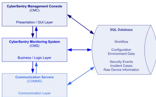
CyberSentry SEM has three logical layers that interact with an SQL database.
Figure 1: Logical layers interacting with the database
The functions performed by each layer of the CyberSentry architecture are outlined as follows:
• CyberSentry Management Console (CMC) — The CMC is the client layer that allows you to monitor CyberSentry SEM activity, perform actions on workflows, and produce compliance reports. This is the interface with which you interact with the program. The CMC is installed on the same computer as the CMS and COMMs layers. The CMC must be open in order for CyberSentry SEM to operate, which means that a user needs to be logged in to the CyberSentry SEM software.
• CyberSentry Monitoring System (CMS) — The CMS is the middle layer where device information is analyzed and monitored for new Security Events and Incident Cases, where the more serious Security Events become Incident Cases. It must be installed and running from an authorized Windows account on the computer.
The default poll rate at which the CMS monitors devices is 30 minutes. This rate can be altered to suit different network architectures, corporate security, and communication approaches. The rate can range from 15 minutes to 12 hours.
• Communication Servers (COMMS) — The communication layer provides an interface directly to field devices. This layer collects data and provides it to the CMS layer.
CyberSentry Management Console (CMC)
Presentation / GUI Layer
CyberSentry Monitoring System
(CMS)
Business / Logic Layer
Communication Servers (COMMS) Communication Layer SQL Database Workflow Configuration Environment Data Security Events Incident Cases Raw Device Information
CHAPTER 1: INTRODUCTION HOW CYBERSENTRY WORKS
CyberSentry workflow
There are two phases:
Phase 1 — Setup — Configure CyberSentry with details of the system to be monitored Phase 2 — Monitor — CyberSentry is fully operational and used daily to monitor the system and create reports
Figure 2: Phase 1 is configuration
Figure 3: Phase 2 is monitoring
In other words, the process for installing and using CyberSentry SEM is as follows:
• Install the software
• Enter the activation code
• Configure preferences
• Configure user accounts
• Configure Security Domains
• Add and assign devices to the Security Domains
• Review and add rules (Authorized Configuration Profiles)
• Check the Security Dashboard and respond to issues, modifying an event/case until it
Step 2: Perform Workflow Actions
Users log in to CyberSentry SEM and manage their assigned activities by updating the workflow status
Step 3: Reports
Create reports to review activity and for auditing
PHASE 2: MONITOR
(daily activity)
Step 1: Monitor Security Events/Incidents
CyberSentry SEM monitors for new Security Events/ Incident Cases and notifies designated owner. Evaluate Security Events/Incident Cases to determine correct action.
HOW CYBERSENTRY WORKS CHAPTER 1: INTRODUCTION
Sample event/case
This section outlines an example of setup and workflow for loss of communication with a device.
Scenario
Create an Authorized Configuration Profile (ACP) for a device that creates a Security Event when communication with a device is lost. Do not "Raise IC".
The Security Domain owner is James Brown.
Configuration
Administrator adds user account for Joe Smith in the Officer category.
Administrator adds user account for James Brown, in the Compliance Officer category. James Brown adds a Security Domain, which is simply a category in which to group devices.
James Brown adds the device and assigns it to the Security Domain.
James Brown adds a security parameter (rule) to monitor communication with the device by adding a Loss of Communication security parameter. By leaving the Raise IC checkbox disabled, any loss of communication is a Security Event instead of a more serious Incident Case.
Figure 4: Add rule to monitor for loss of communication with device
With configuration complete, the software communicates with the device according to the global scanning frequency set in the Preferences, which is also configured to send email notifications.
Workflow
A month later, the software cannot communicate with the device. The Loss of
Communication button on the Security Dashboard changes to red and indicates that there is an issue. James Brown is notified by email of the loss of communication.
Figure 5: Security Dashboard alarm
James Brown clicks the Loss of Communication button to open the event viewer window. He assigns the Security Event to Joe Smith and comments "Joe, can you please see why this device is not communicating. Thanks. James' [Joe gets email]
CHAPTER 1: INTRODUCTION HOW CYBERSENTRY WORKS
Figure 6: Assign event and comment
Joe responds with comments: "James, squirrels chewed through the communication cable. I've attached the picture." He attaches a bitmap image. [James gets email] Joe promotes the Security Event to an Incident Case and reassigns it back to James. [James gets email]
As an Incident Case, James assigns it to Joe: "Joe, please repair the communication cable ASAP. Thanks James" [Joe gets email]
Joe responds with comments: "James, repairs are made and I've rerouted the wiring. I've attached the picture." He attaches a bitmap image. [James gets email]
Joe has completed the work and changes the state to Reviewed. [James gets email] James evaluates Joe's comments and attachment and signs off the Incident Case by closing it with the comment: "Examined photos to approve installation. Device successfully communicating." [no email]
James generates a report for his records, including the details and history. As shown in the figure, this includes the comments.
FOR FURTHER ASSISTANCE CHAPTER 1: INTRODUCTION
Figure 7: Report for loss of communication event
For further assistance
For product support, contact the information and call center as follows: GE Digital Energy
650 Markland Street Markham, Ontario Canada L6C 0M1
Worldwide telephone: +1 905 927 7070
Europe/Middle East/Africa telephone: +34 94 4854 88 54 North America toll-free: 1 877 547 8630
Fax: +1 905 927 5098 E-mail: [email protected]
Website: http://gedigitalenergy.com/multilin
CyberSentry SEM Software
Chapter 2: Getting started
Getting started
System requirements
Operating system
CyberSentry SEM supports the following Windows operating system:
• Windows 7 (32-bit) with the latest service pack and patches
Hardware requirements
The computer requirements are as follows:
• 2.3 GHz (or better) Intel/AMD processor
• 4 GB RAM (minimum 2 GB)
• 1.0 GB free space on hard drive
• Video card supporting 65535 colors
• 17 inch (minimum) monitor
• CD drive (when installing from the CD)
• Ethernet connection
• Keyboard
• Mouse or mouse pad
Software required
The following software must be present on the computer before installing CyberSentry SEM:
• Adobe Reader or compatible viewer for viewing compliance reports
INSTALL THE SOFTWARE CHAPTER 2: GETTING STARTED
• EnerVistaTM Integrator
• EnerVista Energy Aggregator
• EnerVista Viewpoint Monitoring
Either use another computer or uninstall the EnerVista software, ensuring first that the uninstall does not interfere with operation of an electrical grid.
Install the software
The license allows for installation on one computer. Installation typically is done at a substation.
The software typically is installed on a computer shared by multiple users. For example, you install the software, configure four user accounts, and these four users use the computer at different times. Email notifications are sent to the users as appropriate, which allows the users to respond even while not working at the computer that has CyberSentry SEM installed.
CyberSentry SEM can be installed from the CD or a download file. To install the CyberSentry SEM software from the CD:
1. With Adobe Reader installed and EnerVista software not installed, insert the
CyberSentry SEM CD in the computer drive.
2. If the installation program does not automatically start, locate the
CyberSentrySEM100Setup.exe file on the CD, then click or double-click the file to start
the installation. If prompted, click Yes to allow the program to make changes to the
computer, and also allow Microsoft.NET framework to be installed.
3. Complete the wizard.
All components required by CyberSentry SEM are installed. Default user accounts are created automatically.
4. Start the software and log in, as outlined in the next section.
To install the CyberSentry SEM software using the download file:
1. With Adobe Reader installed and EnerVista software not installed, click or double-click
the CyberSentrySEM100Setup.exe file. If prompted. click Yes to allow the program to
make changes to the computer, and also allow Microsoft.NET framework to be installed.
2. Complete the wizard.
All components required by CyberSentry SEM are installed. Default user accounts are created automatically.
3. Start the software and log in, as outlined in the next section.
After installing the software, configure it, working through each chapter in this instruction manual to set preferences, user accounts, monitoring, and so on. This instruction manual is located in the following folder: C:\Program Files\GE Digital Energy\CyberSentry SEM.
Installation notes
CyberSentry SEM uses Microsoft SQL Server 2008 Express database for storage. The name of the SQL Server used is PMCSSQLSERVER. The name of the database is
CHAPTER 2: GETTING STARTED START THE SOFTWARE AND LOG IN
If the database is not attached to the server properly, use the database installation script
DB_CMD.CMD located in the directory
C:\Program Files\GE Digital Energy\CyberSentry SEM\. If your SQL Server instance is named differently, for example SQLEXPRESS instead of PMCSSQLSERVER, change the script and run the script. You need to be logged in as computer administrator to replace the file.
Default user accounts
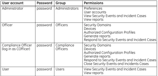
Four user accounts and four user groups are created by default.
Start the software and log in
A user needs to be logged in for the software to run. To start the software and log in:
1. Click the CyberSentry SEM desktop icon, or click Start > All Programs > GE Digital
Energy > CyberSentry SEM.
2. In the login window, enter the user name and password. For first login, use the
Administrator account and password of "password". When logging in to the default
Compliance Offcer account, enter the user name of COfficer.
If a message displays that "Your account has been disabled" this means that the user account has been temporarily disabled by the Administrator; ask the Administrator to enable the user account or log in with another account.
Table 1: Default user accounts
User account Password Group Permissions Administrator password Administrators Preferences
User accounts
View Security Events and Incident Cases View reports
Officer password Officers Security Domains
Devices
Authorized Configuration Profiles Generate reports
Respond to Security Events and Incident Cases Compliance Officer
(log in as COfficer) password Compliance Officers Security DomainsDevices
Authorized Configuration Profiles Generate reports
Respond to Security Events and Incident Cases Close Security Events and Incidents Cases
User password Users View Security Events and Incident Cases
START THE SOFTWARE AND LOG IN CHAPTER 2: GETTING STARTED
Figure 8: Login window
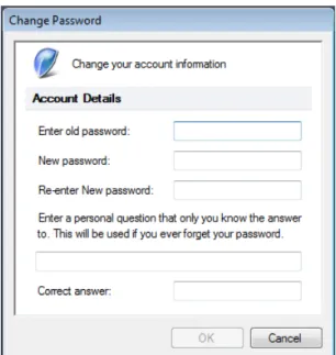
3. With first login for any of the default user accounts, a window prompts to specify a
new password and security question for the account. Complete the information.
4. To lock the computer and leave the software running, press the Ctrl+Alt+Delete keys,
then click the Lock this computer option.
Figure 9: Prompt to change password and enter security question
After three unsuccessful password attempts, CyberSentry SEM shuts down. A message displays to that effect, and a system log (syslog) message is generated.
With successful launch, the Security Dashboard displays (next figure).
With successful installation and login, configure the software, working through each
chapter in this instruction manual, which is located in the following folder:
C:\Program Files\GE Digital Energy\CyberSentry SEM. Start by entering the activation code (next section) and configuring preferences (next chapter).
CHAPTER 2: GETTING STARTED ENTER THE ACTIVATION CODE
Figure 10: Security Dashboard in the software interface
Enter the activation code
A valid license and activation code are required to run the software. Enter the activation code after installation of the software.
To enter the activation code:
1. While logged in to CyberSentry SEM as Administrator, click System > License.
2. In the window that opens, enter the code in the Activation Code field, then click the
Unlock button.
3. Click the OK button to exit.
Using the trial version
On a freshly installed CyberSentry SEM system, a 90-day trial period is provided. After the trial period, the software locks, and you must have a valid activation code to unlock it. Based on the license purchased, CyberSentry SEM limits the number of devices that can be configured in Security Domains to 25, 50, 100, or 150 devices. When in demonstration/trial mode, the number of devices is limited to 25.
To view license status:
1. While logged in as Administrator, click System > License.
MENU STRUCTURE CHAPTER 2: GETTING STARTED
Figure 11: View license status
To enter the activation code:
1. See the previous section.
Menu structure
CyberSentry SEM has the following tabs:
• Home
• System
• Security Dashboard
To open the online help, click the question mark icon on the right side of the software window.
Home tab
Use this tab to access status windows, log out, and exit the software.
Figure 12: Home tab
Logout — To log out of a user account and stop monitoring.
Exit — To log out, stop monitoring, and shut down the software.
Online — To display current status of the software. See the Security dashboard chapter.
Scan — To display details of CyberSentry SEM’s device scanning. See the Security
dashboard chapter.
Error — To display details of any known error conditions detected by CyberSentry SEM. See the Security dashboard chapter.
System tab
This tab provides access to administration and configuration functions.
CHAPTER 2: GETTING STARTED LOCK COMPUTER
Users —To manage user accounts. Non-administrators can manage their personal
information. See the User accounts chapter.
Preferences — To manage system preferences, such as scan rate, email notification, and
system logging. See the Preferences chapter.
License — To manage the software license and view version. See the License management chapter.
SDs — To manage the Security Domains and devices. See the Security domains chapter.
ACPs — To manage the Authorized Configuration Profiles, which are the rules applied
during monitoring. See the Authorized configuration profiles chapter.
Profiles — To add profiles for third-party or customized Modbus/SNMP devices. See the
Device profiles chapter.
Security Dashboard tab
This tab provides functions available for the Security Dashboard window and events/cases.
Figure 14: Security Dashboard tab
Dashboard — To hide/show the Security Dashboard. See the Security dashboard chapter. Event Viewer — To open the Event Viewer window. This is the window used to view,
respond, and close events and cases. See the Event/case workflow chapter.
Create — To enter an Incident Case. See the Event/case workflow chapter. Reports — To generate a report. See the Compliance reports chapter.
Lock computer
A user needs to be logged in for the software to monitor devices. An alternative to logging out is to lock the computer, which leaves the software running.
To lock the computer:
1. Press the Ctrl+Alt+Delete keys, then click the Lock this computer option.
Log out
A user needs to be logged in for the software to monitor devices. To log out:
1. Click Home > Logout. CyberSentry SEM logs out of the user account and displays the
EXIT THE SOFTWARE CHAPTER 2: GETTING STARTED
Exit the software
The software needs to running for it to monitor devices. To exit the software:
1. Click Home > Exit.
2. Confirm the exit at the prompt. The CyberSentry SEM software closes all
communications channels, shuts down, and no longer monitors devices.
Uninstall the software
To uninstall the software:
1. Click Start > Control Panel.
2. Click Programs and Features.
3. Click CyberSentry SEM.
4. Click Uninstall, and confirm the deletion. The software is deleted. The database is
detached but not yet deleted.
CyberSentry SEM Software
Chapter 3: Preferences
Preferences
There are four panels to manage preferences. Configure them after installation.
• General — scan rate and system tray notification
• Emailing — email notification
• Syslog — log events
• Compliance Reports — configure report location and logo
Administrator access is required.
Set scan rate and notification
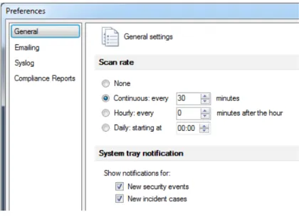
Use the General panel to configure scan frequency and system tray notification, which is on by default.
To set scan rate and notification:
1. Log in to the CyberSentry SEM software as Administrator.
2. Click System > Preferences.
3. Configure the settings, which are explained as follows.
SET SCAN RATE AND NOTIFICATION CHAPTER 3: PREFERENCES
Figure 15: General tab to set scan frequency (default settings shown)
Scan rate
The scan rate is the frequency at which devices are monitored/polled. None
To stop scanning, such as for maintenance, when performing configuration, or when the network is down and you want to avoid unwanted messages.
Continuous (default)
Range: 15 to 720 minutes (12 hours) Default: 30 minutes
Hourly
Selection: 0 to 45 minutes, in increments of 15 minutes Default: 0 minutes
Daily
Range: mm:ss
Default: 00:00 (midnight)
System tray notification
Messages appear by default in the system tray on the Windows taskbar when new Security Events and/or Incident Cases are detected. Notification can be turned on and off.
Figure 16: Notification of event/case in system tray
New security events
Enable to display notification when a new Security Event is detected. New incident cases
CHAPTER 3: PREFERENCES SET EMAIL NOTIFICATION
Set email notification
CyberSentry SEM can be configured to send emails when it detects new Security Events, Incident Cases, or other parameters. Recipients are based on the parameter.
An example of an email notification is the following for a missed deadline to respond to an event/case:
Subject: [CyberSentry SEM 12-000011] Deadline Date Expired Case: CS12-000011
Activity: Deadline Date Expired Deadline: 2012-09-22
GE recommends configuring this function, which is disabled by default.
An email server compliant with the Simple Mail Transfer Protocol (SMTP) is required, located within your company.
To set email notification:
1. Log in as Administrator.
2. Click System > Preferences.
3. Click the Emailing option.
4. Configure the settings, which are explained as follows.
5. Click the Test button to send a test email to the user with the message "This is a test
email from CyberSentry SEM."
When an address is entered here that is not registered in the software for the user, a
message displays to that effect; add the address under System > Users.
If nothing happens when you click the button, this means that you do not have an SMTP server configured correctly in the panel or there is a connection issue with it.
SET EMAIL NOTIFICATION CHAPTER 3: PREFERENCES
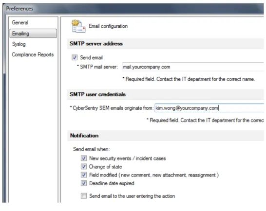
Figure 17: Emailing panel to set email notification
SMTP server address
Send email
Enable to send emails for the notification types specified in this panel. SMTP mail server
Specify the name of your server, such as hpserver or mail.yourcompany.com. Do not specify the path. Servers located at Internet service providers (ISPs) are not supported; the SMTP server needs to be your own, located within your network.
SMTP user credentials
CyberSentry SEM emails originate from
Enter the email address to be used in the From field of emails sent. This address is
typically that of the Administrator of CyberSentry SEM. An example is [email protected]
Notification
Specify when to send email notifications. New security events / incident cases
Default: Enabled
Enable to send an email when a Security Event or Incident Case is created. Send the email to the owner, the assignee, and (when enabled separately) the user performing the
activity. When the Incident Case is created by enabling the Raise IC checkbox or a
Security Event was manually entered, a "New incident cases" email is sent. Otherwise, a "New security events" email is sent.
CHAPTER 3: PREFERENCES CONFIGURE SYSLOG
Change of state Default: Enabled
Enable to send an email when a Security Event or Incident Case changes state. Examples of state changes are when a Security Event is assigned, when a request is made to review an Incident Case, and when a deadline date expired. Send the email to the owner, the assignee, and (when enabled separately) the user performing the activity. Field modified
Default: Enabled
Enable to send an email when a field has been changed for an event/case, for example Add Comment or Add Attachment, or the Security Event or Incident Case has been reassigned to another office. Send the email to the owner, the assignee, and (when enabled separately) the user performing the activity.
Deadline date expired Default: Enabled
In the Event Viewer window, when a comment is made on an event/case or the event/ case is assigned to another user, for example, a deadline is specified and added by the software to the event/case. Enable this checkbox to send an email when the deadline date for an event has expired. Send the email to the owner and the assignee.
Send email to the user entering the action Default: Disabled
Enable to send email notifications to the person performing the activity that causes the notification. Disable to reduce the amount of email sent and do not send an email to person who initiated the activity because they already know about the activity. Leave disabled to minimize email.
Configure syslog
Several types of system action can be recorded in system logs (syslogs). An example of a syslog message is as follows for a closed Incident Case:
8/22/2012 14:52:42.827: Email id da55951a-278d-4bd6-a4fa-f6175af8d4af To:[email protected], [email protected]
Subject:[CyberSentry SEM 12-000640] IC Closed Case: CS12-000640
Activity: Incident Case Closed Time: 2012-08-10 13:57:50 Description: IC resolved and closed The figure shows an example of a syslog.
CONFIGURE SYSLOG CHAPTER 3: PREFERENCES
Figure 18: Syslog example
The computer clock is used for timestamps in the syslogs. Logging is disabled by default.
At least one remote server is required, such as a UNIX server. The logs can be sent to one or two servers, referred to as primary and secondary. An example of a free syslog server is Kiwi Syslog Server, shown in the previous figure.
The syslog message format conforms to the Augmented Backus-Naur Form (ABNF) (RFC 5234) definition.
To configure system logging:
1. Log in as Administrator.
2. Click System > Preferences.
3. Click the Syslog option.
4. Configure the settings, which are explained as follows.
5. Click the Test button(s) to confirm access of the servers.
CHAPTER 3: PREFERENCES CONFIGURE SYSLOG
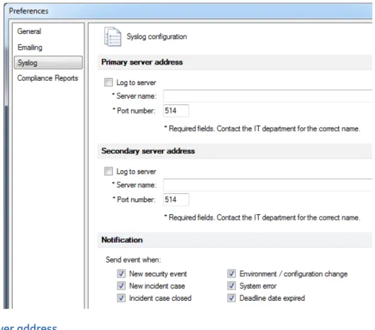
Figure 19: Syslog panel to configure system logs (default settings shown)
Primary server address
Log to server
Enable to log events/cases and software activity, such as a user adding a security parameter in the software, to system logs on the main remote server.
Server name
Specify the name of the main remote server, such as hpuxserver. Do not specify the path. The maximum number of characters is 80.
Port number Default: 514
Specify the port number on the main remote server used for communication. Port 514 typically is used for syslogs.
Secondary server address
Use of a second server is optional. Log to server
Enable to log events/cases and software activity, such as a user adding a security parameter in the software, to system logs on a second remote server.
Server name
Specify the name of the second remote server, such as hpuxserver2. Do not specify the path. The maximum number of characters is 80.
CONFIGURE SYSLOG CHAPTER 3: PREFERENCES
Port number Default: 514
Specify the port number on the second remote server used for communication. Port 514 typically is used for syslogs.
Notification
Specify the activities that generate an entry in the syslog. New security event
Default: Enabled
Enable to record in the syslog when a Security Event is created. New incident case
Default: Enabled
Enable to record in the syslog when an Incident Case is created. Incident case closed
Default: Enabled
Enable to record in the syslog when an Incident Case is closed. Environment / configuration change
Default: Enabled
Enable to record in the syslog when device configuration is changed. Examples are "User FirstOfficer Added SP Control Password Access for Timeout for Device B90_ver600" and "User FirstOfficer Added SP Session for Device N60_version540."
System error Default: Enabled
Enable to record in the syslog when a system error is generated. An example is the message "SMTP Error: Check the system."
Deadline date expired Default: Enabled
In the Event Viewer window, when a comment is made on an event/case or the event/ case is assigned to another user, for example, a deadline is specified and added by the software to the event/case. Enable this checkbox to record in the syslog when the deadline date for an event/case has expired.
CHAPTER 3: PREFERENCES CONFIGURE COMPLIANCE REPORTS
Configure compliance reports
Specify the calendar week, location of the reports, and a logo.
Figure 20: Compliance Reports panel to specify report location
To configure reports:
1. Log in as Administrator.
2. Click System > Preferences.
3. Click the Compliance Reports option.
4. Configure the settings, which are explained as follows.
5. Click the OK button to exit.
Calendar week definition Default: Monday to Sunday
Specify the calendar week for the reports as Monday to Sunday or as Sunday to Saturday.
Reports file location
Default: C:\Users\Public\Public Documents
Specify where the reports are stored when created. Enter the full path. Any computer
accessible through the Browse function can be used. You cannot use an HTTP path. Any
user with access to the computer can view the reports when they know the path to the location.
Logo file location
Default: C:\ProgramData\GE Digital Energy\CyberSentry SEM\Reports\Report_Logo.png To include a logo on the compliance reports, specify the path to the file. An example is C:\Documents and Settings\My Documents\My Pictures. Use a square image. If you specify a non-square image, it is cropped in this panel but later scaled to fit the report, which means that it is formatted as square (and distorted) when a report is generated. The formats supported are BMP, JPG, GIF, and PNG. An error message displays when an
CyberSentry SEM Software
Chapter 4: User accounts
User accounts
The Administrator can manage user accounts. All other users can manage their contact information, address, and password.
After installation, as a minimum, change the passwords and set the email addresses for the Administrator and Compliance Officer accounts.
During installation, Administrator, Compliance Officer, Officer, and User accounts were created by default. Upon first login for each account, change the default password of "password". Each account is a member of their respective user group, and access to functions depend on permissions.
The following functions are based on permissions:
• Add, update, delete, disable user accounts
• View permissions
• Update contact information
• Change password
• Forgot password
Table 2: Default user accounts
User account Password Group Permissions Administrator password Administrators Preferences
User accounts
View Security Events and Incident Cases View reports
Officer password Officers Security Domains
Devices
Authorized Configuration Profiles Generate reports
Respond to Security Events and Incident Cases Compliance
Officer (log in as COfficer)
password Compliance
Officers Security DomainsDevices
Authorized Configuration Profiles Generate reports
Respond to Security Events and Incident Cases Close Security Events and Incidents Cases
User password Users View Security Events and Incident Cases
ADD, UPDATE, DELETE, DISABLE USER ACCOUNT CHAPTER 4: USER ACCOUNTS
Add, update, delete, disable user account
The Administrator performs these functions.
A user is a member of a group and only one group. Only one Administrator account is possible.
Figure 21: Managing user accounts
Add user account
CyberSentry SEM supports 1,000 user accounts. To add a user account:
1. Log in as Administrator.
2. Click System > Users.
3. Click a user account category/group on the left side, such as Officers, which is the
core group to respond to Security Events. The types are explained in the View
permissions section that follows. Because only a single Administrator account is allowed, this group is not selectable.
4. Click the New User icon. As a minimum, enter a user name, first and last name, and
email address.
5. Click the OK button to add the account and exit. The default password for the user is
"password". The user can set the password and security question when they log in.
6. Access the panel again and click the Test button for the email account. This sends a
test email to the user with the message "This is a test email from CyberSentry SEM."
The email server needs to be configured under System > Preferences for this function
to work, otherwise a message displays to that effect. When incorrectly configured,
nothing happens when you click the Test button.
User name
The user name for login must be unique and between 4 and 20 characters long. Once set, only the Administrator can change it.
CHAPTER 4: USER ACCOUNTS ADD, UPDATE, DELETE, DISABLE USER ACCOUNT
Update user account
To update a user account:
1. Click System > Users.
2. Select the user account. When the user logged in belongs to the Users, Officers, or
Compliance Officers group, the list displays that account only. Administrators see the entire user list.
3. Change the information. All users can update their Contact Information, Address, and
Password. Only the Administrator can change a user name. The Administrator cannot change the password of another user.
4. Click the OK button to exit.
Delete user account
An alternative to deleting a user account is to disable it. See the Disable user account
section that follows.
Deleted accounts cannot be recovered. Any Security Events and Incident Cases assigned to them remain available to other users.
To delete a user account:
1. Log in as Administrator.
2. Click System > Users.
3. Select the user account.
4. Click the Delete icon. A user cannot delete their own account; ask the Administrator to
delete it.
5. At the prompt, confirm the deletion. Before the account is deleted, CyberSentry SEM
checks the system for active Security Events and Incident Cases that are assigned to the account. When there are any matches, a message indicates the number of records assigned to the user, and the account is deleted. Any Security Events and Incident Cases assigned to the user remain visible in the system and available to other users. They can be picked up by any Officer or Compliance Officer.
6. Click the OK button to exit.
Disable user account
An alternative to deleting a user account is to disable it. A disabled user account cannot log in to the software. Any Security Events and Incident Cases assigned to it remain available to other users.
To disable a user account:
1. Log in as Administrator.
2. Click System > Users.
3. Select the user account.
4. Click the Disable button, which displays only for the Administrator. The Administrator
account cannot be disabled. Before an account is disabled, CyberSentry SEM checks the system for active Security Events and Incident Cases that are assigned to the account. When there are any matches, a message indicates the number of records
VIEW PERMISSIONS CHAPTER 4: USER ACCOUNTS
the user is unable to log in. Any Security Events and Incident Cases assigned to the user remain visible in the system and available to other users. They can be picked up by any Officer or Compliance Officer.
Figure 22: Disable a user account
View permissions
There are four types of user accounts/groups, which determine the permissions:
• Administrator
• Compliance Officer
• Officer
• User
All user accounts in a group share the same permissions. Permissions cannot be customized.
To view permissions:
1. Click System > Users.
2. Select a user group or user account. The permissions display at the top of the window
and are explained as follows. They cannot be modified. Administrator
The Administrator can view all information, manage user accounts, and view reports. They cannot modify the Security Domain (SD), device configuration, or perform action on Security Events and Incident Cases.
One Administrator account is allowed.
Figure 23: Permissions for the Administrator
Compliance Officer
A Compliance Officer can view and edit information about device and security parameters, as well as workflow and compliance reports. They can manually raise Incident Cases. They can close Security Events and Incident Cases. They cannot manage user accounts other than their own.
CHAPTER 4: USER ACCOUNTS VIEW PERMISSIONS
Figure 24: Permissions for a Compliance Officer
Officer
An Officer is the core group that responds to Security Events. They have the same permissions as Compliance Officers except that they cannot close events/cases.
Figure 25: Permissions for an Officer
User
A User can view workflows, meaning events/cases. They can view compliance reports.
UPDATE CONTACT INFORMATION CHAPTER 4: USER ACCOUNTS
Update contact information
All users can update their contact information except the User name field, which the
Administrator changes. The Administrator can view all contact information.
Figure 27: Contact Information and Address fields
To update contact information:
1. See the Update user account section.
Change password
The rules for passwords are as follows:
• Length between 6 and 20 characters
• Contain a minimum of one lowercase letter (a - z)
• Contain a minimum of one uppercase letter (A - Z)
• Contain a minimum of one number (0 - 9)
• Contain a minimum of one special character from !@#$%*
Although "password" is used as the default password, this word cannot be expressly set as a password. When any user attempts to log in with the password of "password", they are prompted to change the password.
A user changes their own password. The Administrator cannot change it.
Passwords are encrypted in the database. There is no connection to Microsoft Active Directory or the Remote Authentication Dial In User Service (RADIUS) protocol. To change a password:
1. Click System > Users.
2. Select the user account.
3. Click the password Update button and complete the form.
CHAPTER 4: USER ACCOUNTS FORGOT PASSWORD
Figure 28: Change the password
Forgot password
When a user forgets their password, they reset it by clicking the Reset password button in
the login window. To reset the password:
1. In the login window, click the Reset password button. When no security question
exists for the account, such as for a default user account, a message displays to that effect. In this case, log in with the default password of "password" and set the security question.
2. In the window that opens, enter the Answer to the security question displayed. The
answer is case-sensitive. Click OK.
3. In the password reset window that opens, enter a new password, security question,
GROUPS CHAPTER 4: USER ACCOUNTS
Figure 29: Answer the security question to reset the password
Groups
There are four fixed user groups: Administrators, Users, Officers, and Compliance Officers. They cannot be renamed, and you cannot add or delete groups.
CyberSentry SEM Software
Chapter 5: Security domains
Security domains
A Security Domain (SD) is a set of devices. The purpose of Security Domains is to group devices in order to apply rules for monitoring. All devices monitored by CyberSentry SEM must be in at least one Security Domain.
The following action can be performed. To configure the software the first time, you add domains, add devices, and assign them to domains.
• Add, update, delete Security Domains
• Add devices
• Assign devices to the domains
• Delete devices
Users in the Compliance Officer and Officers groups modify these functions. Administrators can view them.
Add, update, delete security domain
The advantage of naming domains is that each domain has its own set of rules, referred to as Authorized Configuration Profiles (ACPs). The ACPs define how CyberSentry SEM determines Security Events and Incident Cases.
Add security domain
To add a Security Domain:
1. Log in as a Compliance Officer or Officer.
2. Click System >SDs.
3. Click the New SD icon.
4. Complete the fields, which are explained as follows, and click the OK button to exit.
The order of the domains displayed cannot be changed later, so add them in the order in which you want them to appear. Because devices have yet to be assigned to the
ADD, UPDATE, DELETE SECURITY DOMAIN CHAPTER 5: SECURITY DOMAINS
Figure 30: Add a Security Domain
Name
The name of the Security Domain, such as SD1, UR_Devices, or Markham. Security policy
Type a description of the policy. An example is "Testing" or "Connection Monitoring" or "Login Monitoring Only."
Owner
Select an Officer or Compliance Officer to be the owner of the domain. The user accounts are listed by first and last name, not user name.
Update security domain
The order of the domains cannot be modified. To update a Security Domain:
1. Log in as a Compliance Officer or Officer.
2. Click System >SDs.
3. Click the Security Domain.
4. Update the fields.
5. Click the OK button to exit.
Delete security domain
To delete a Security Domain:
1. Log in as a Compliance Officer or Officer.
2. Click System >SDs.
3. Click the Security Domain.
4. Click the Delete icon, and confirm the deletion.
CHAPTER 5: SECURITY DOMAINS ADD DEVICE
Add device
The following devices can be monitored: UR series (versions 5.4x to 6.0x); URPlus series
(versions 1.7x and 1.8x); ML2400 (version 4.01); Modbus; and SNMP.
When adding a device, you select a protocol (Modbus or SNMP), then complete the fields.
The UR and URPlus devices are Modbus devices. The ML2400 is an SNMP device. When in
doubt, view the device profile under System > Profiles.
Depending on the CyberSentry SEM license, 25, 50, 100, or 150 devices can be added. When in trial/demonstration mode, the number of devices is limited to 25.
To add a device:
1. If the device is a third-party device, add its profile under System > Profiles. See the
Device profiles chapter.
2. Log in as a Compliance Officer or Officer.
3. Click System >SDs.
4. Select the Security Domain on the left side.
5. Click the New Device icon.
6. Select the Protocol from the drop-down list. Select Modbus for UR and URPlus devices.
Select SNMP for the ML2400.
7. From the Device type drop-down list, select the device, then click the Test
communication button for SNMP or Read order code button for Modbus to verify communication with the device.
8. Complete the remaining fields, which depend on the communication protocol
(Modbus or SNMP) and which are explained as follows. Examples of device names are UR, B30, and ML2400.
9. Click the OK button to exit.
Modbus parameters
Modbus TCP/IP is supported, where Modbus is a serial communications protocol used to communicate with devices. Three parameters are required: IP address, Modbus port number, and a Modbus slave address.
ADD DEVICE CHAPTER 5: SECURITY DOMAINS
Figure 31: Configure Modbus parameters for a device
IP address
The IP address of the device. View it in the EnerVista software or on the front panel of the device itself.
Modbus port Default: 502 Slave address Default: 254
On the same IP address you can have different devices that differ by slave address. So if you have more than one device using the IP address, enter the device’s slave address here.
Order Code
For the built-in Modbus devices, CyberSentry SEM can communicate with the device to
determine the device order code. Click the Read order code button, or manually enter
the code. Version
For the built-in Modbus devices, CyberSentry SEM can communicate with the device to
determine the device version number. Click the Read order code button, or manually
CHAPTER 5: SECURITY DOMAINS ADD DEVICE
SNMP parameters
SNMP versions 1, 2, and 3 are supported. Configuration is required for CyberSentry SEM to establish an SNMP link to the network device. The ML2400 supports all three versions of SNMP. Use the version for which your device is configured.
SNMP 1 and 2 require a password string when the SNMP device has security enabled for any (read) actions that are performed.
The Ports and services button is explained later.
Figure 32: Configure for SNMP versions 1 and 2
For SNMP version 3, more fields are completed because it uses a higher level of security than versions 1 and 2.
Figure 33: Configure for SNMP version 3
Security name
The name is available in the web interface for your device or in its manual. Context name
The name is available in the web interface for your device or in its manual. Authentication
ASSIGN DEVICE TO SECURITY DOMAIN CHAPTER 5: SECURITY DOMAINS
Privacy
This refers to encryption used.
DES — Data Encryption Standard. Developed by IBM. 56 bits.
AES — Advanced Encryption Standard. Supersedes DES. 128, 192, or 256 bits.
Assign ports and services
Ports are entered for Modbus and SNMP by clicking the Ports and services button. Use this
function to create an information list for users of the system, for example the ports that you open. CyberSentry SEM uses the information for documenting setup only; the ports are not used or altered by CyberSentry SEM.
Examples of entries are port 514 opened in the firewall for syslog, UDP port, TFTP port, and
port 23 for UR and URPlus to retrieve events.
To enter a port or service:
1. Click the Ports and services button.
2. Enter a name, such as UDP. Select port or service from the Type drop-down list. Enable
it. Add a description. Click the OK button to exit. The port or service is now associated
with the protocol.
Figure 34: Configure port for Modbus or SNMP communication
Assign device to security domain
Each device must be assigned to one or more Security Domains. The concept is shown in the following figure. Each domain has its own rules for CyberSentry SEM to determine Security Events and Incident Cases.
CHAPTER 5: SECURITY DOMAINS ASSIGN DEVICE TO SECURITY DOMAIN
Figure 35: Group devices by adding to one or more Security Domains
To assign a device to a Security Domain:
1. Log in as a Compliance Officer or Officer.
2. Click System >SDs.
3. Expand the domain list and select a device.
4. Click the Assign icon.
5. In the window that opens, enable the checkboxes for the domains to which the
devices belongs.
6. Click the OK button to exit.
7. For UR, URPlus, and ML2400 devices, access the ACPs panel to check the rules added
by default for the device (next chapter).
Figure 36: Assign device to a Security Domain
Device A
Device D
Device C Device B
Device E
Device F
Device G
Security Zone 1 (SD)
Security Zone 2 (SD)
Security Zone 3 (SD) ACP Rules 1
ACP Rules 2
DELETE DEVICE CHAPTER 5: SECURITY DOMAINS
Delete device
A device can be removed from a Security Domain and/or the system. To delete a device:
1. For devices that have associated Authorized Configuration Profiles (ACPs), delete the
ACPs for the device. (Click the System tab, then the ACPs icon.)
2. Log in as a Compliance Officer or Officer.
3. Click System >SDs.
4. Select the device.
5. Click the Delete icon, and confirm the deletion. When the device belongs to more than
one domain, a message asks if you want to remove the device from the other domains too. When the device has ACPs associated with it, a message displays asking you to
remove them first (see figure); go to System > ACPs.
CyberSentry removes the device from the domains and the system (but not the device profiles). The device Security Events and Incident Cases remain in the database, visible in the Event Viewer.
CyberSentry SEM Software
Chapter 6: Authorized configuration
profiles
Authorized configuration profiles
An Authorized Configuration Profile (ACP) is a set of rules applied to a Security Domain and the devices in the domain. CyberSentry SEM uses the rules to determine when Security Events and Incident Cases have occurred. An Incident Case is more serious than a Security Event; some Security Events become Incident Cases, while an Incident Case cannot become a Security Event.
Individual security parameters are created that comprise the ACPs. Some are added by
default as examples for UR and URPlus devices.
The following action can be performed. When configuring the software for the first time, you add ACP rules.
• Add ACP security parameter
• Delete ACP security parameter
Users in the Compliance Officers and Officers groups modify these functions. Administrators can view them.
Types of security parameters
Several types are rules can be applied to devices: Configuration Changes, Device Events, Loss of Communication, Security, and System. Device support is outlined in the table.
Table 3: Security parameters
Security parameter Devices supported
Configuration Changes UR
URPlus ML2400
Device Events UR
URPlus ML2400
TYPES OF SECURITY PARAMETERS CHAPTER 6: AUTHORIZED CONFIGURATION PROFILES
Security parameters are automatically created as examples for supported UR, URPlus, and
ML2400 devices. By editing the profile of a device, data items can be added to the categories (Configuration Changes, Device Events, Security). Review and customize security parameters, add new ones, and/or delete those not used.
The software supports positive and negative logic. Positive logic is supported in the Configuration Changes, Device Events, and Loss of Communication categories. Examples are detecting any settings change for a relay and detecting when the firmware run by the relay changed. Negative logic refers to expected values or expected range of values. It is supported in all categories. An example is setting a software trigger when there are more than three invalid password attempts.
Enable the Raise IC checkbox to create Incident Cases when issues are detected. Disable
the checkbox to create a Security Event instead.
Configuration changes
These rules monitor settings and password changes in the devices.
Figure 37: Monitor device for configuration change
The following Configuration Change ACPs are automatically created as examples for UR
and URPlus devices:
• Setup change (without entering password)
• Firmware change (firmware version reported by device differs from that entered by
user in CyberSentry SEM)
• Password — Any change
Loss of Communication UR
URPlus ML2400 Modbus SNMP
Security UR
URPlus ML2400
System ML2400
Table 3: Security parameters
CHAPTER 6: AUTHORIZED CONFIGURATION PROFILES TYPES OF SECURITY PARAMETERS
Device events
These rules use events recorded to detect a specific condition. Events retrieval is
supported for UR, URPlus, and ML2400 devices. It is not supported for other devices.
Figure 38: Monitor device using events recorded
Table 4: Examples of device event values Default
monitoring for devices?
Value Description
UR, URPlus UNAUTHORIZED ACCESS Failed login attempt UR, URPlus REMOTE ACCESS DENIED Failed remote login attempt UR, URPlus ACCESS LOC SETG ON Local setting access enabled
ACCESS LOC SETG OFF Local setting access disabled UR, URPlus ACCESS LOC CMND ON Local command access enabled
ACCESS LOC CMND OFF Local command access disabled UR, URPlus ACCESS REM SETG ON Remote setting access enabled
ACCESS REM SETG OFF Remote setting access disabled UR, URPlus ACCESS REM CMND ON Remote command access enabled
ACCESS REM CMND OFF Remote command access disabled LOC SET ACCS AUT OFF Local setting access authorization disabled UR, URPlus LOC SET ACCS AUT ON Local setting access authorization enabled
REM SET ACCS AUT OFF Remote setting access authorization disabled UR, URPlus REM SET ACCS AUT ON Remote setting access authorization enabled
POWER ON Device was turned on
POWER OFF Device was turned off or power was lost
UR, URPlus EVENTS CLEARED Events record was manually cleared RELAY IN SERVICE Device was placed in service/in operation RELAY OUT OF SERVICE Device was taken offline/out of service
OSCILLOGRAPHY CLEAR The oscillographic graphs were manually cleared
DATE/TIME CHANGED Date or time was changed
REBOOT COMMAND Device restarted
ML2400 INFO-Authentication Traps Disabled
ML2400 INFO-Port Security Disabled ML2400 INFO-Authentication Disabled plus more for ML2400 devices
TYPES OF SECURITY PARAMETERS CHAPTER 6: AUTHORIZED CONFIGURATION PROFILES
Figure 39: Default event monitoring for UR and URPlus devices
Loss of communication
This parameter is monitored by default for UR, URPlus, and ML2400 devices. It is also
available for any third-party Modbus or SNMP device.
As shown in the following figure, you can set the software to raise an Incident Case when it loses communication with a device. This parameter creates a Security Event or Incident Case each time CyberSentry SEM loses communication.
For any device, an attempt is made to read the first label in the device profile (for example 750_700.xml). If the read is successful, the device is deemed to communicate. If not, a Security Event or Incident Case is generated. (For more information on device profiles, see the Device profiles chapter.)
Figure 40: Monitor device for loss of communication
Security
These rules are based on a predefined list of security-related Modbus and SNMP registries. There are no entries by default.
An example is to raise an Incident Case for more than three incorrect password attempts
for login to a device. Set the Parameter field to Invalid Password Attempts, set the
Condition field to "greater than," and set the Value 1 field to 3. Enable the Active and Raise IC checkboxes.
CHAPTER 6: AUTHORIZED CONFIGURATION PROFILES TYPES OF SECURITY PARAMETERS
Figure 41: Monitor device for Modbus security
Access Authorized Timeout
The timeout delay for local setting access. Command Password
The password used for the following functions: changing the state of virtual inputs; clearing the event records; clearing the oscillography records; changing the date and time; clearing the data logger; and clearing the user-programmable pushbutton states. Control Password Access Time
The length of inactivity (no local or remote access) required to return to restricted access from the command password level. The length of inactivity required before returning to the restricted access level.
Invalid Password Attempts
When the number of failed password attempts to the device is greater than a specified value, raise a Security Event or Incident Case.
Local Setting Authorized
Local (front panel or RS232 interface) setting access supervision. Password Access Events
Recording of password access events in the event recorder. Password Lockout Duration
The time that the device locks out password access after the number of invalid password entries specified.
Remote Setting Authorized
Remote setting access supervision. When on, remote setting access is possible, using a password. When off, remote setting access is blocked, even with the correct remote setting password entered.
Setting Password
The password for changing settings. Setting Password Access Time
ADD ACP SECURITY PARAMETER CHAPTER 6: AUTHORIZED CONFIGURATION PROFILES
Add ACP security parameter
Each Security Domain has its own ACP rules for each security category. An example of an ACP is "Loss of Communication." When monitoring a device for Loss of Communication, a Security Event or Incident Case is raised when contact with the device is lost.
You select the Security Domain, then the ACP.
Users in the Compliance Officers and Officers groups can add them. To add an ACP:
1. Log in as a Compliance Officer or Officer.
2. Click System > ACPs.
3. Select the security parameter category, such as Configuration Changes or Loss of
Communication.
4. Click the New SP icon.
5. Complete the fields and click OK. See the previous section for guidance.
6. Click the refresh button to display the real-time device values.
Delete ACP security parameter
Rules can be deleted. When deleting a device, the ACP security parameters associated with the device must first be deleted.
To delete an ACP security parameter:
1. Log in as a Compliance Officer or Officer.
2. Click System > ACPs.
3. Select the security parameter category, such as Configuration Changes or Loss of
Communication.
4. Select the rule by clicking its name in the Parameter column.
5. Click the Delete SP icon. The security parameter is deleted.
CyberSentry SEM Software
Chapter 7: Security dashboard
Security dashboard
The Security Dashboard is part of the main interface. It allows access to events, cases, devices, and so on. It is viewable by all users.
The following topics are outlined in this chapter:
• Check status using the taskbar
• Scan devices
• Security Dashboard explained
Check online, scan, and error statuses
The taskbar at the bottom of the dashboard indicates online, scan, and error statuses. It provides the ability to manually invoke a scan.
Times are displayed using the 24-hour format, using the computer’s clock. This includes preferences, emails, dashboard, and compliance reports. The timestamp for the taskbar follows the format mm/dd hh:mm:ss. An example is 04/16 09:28:26 for April 16 at 9:28 and 26 seconds in the morning.
Figure 42: Taskbar
To show or hide the taskbar:
1. Double-click anywhere outside the Security Dashboard in the main window. Or
enable/disable the Status Bar checkbox in the Security Dashboard tab.
To check online, scan, or error status:
1. View the appropriate icon on the taskbar.
CHECK ONLINE, SCAN, AND ERROR STATUSES CHAPTER 7: SECURITY DASHBOARD
Table 5: Taskbar icons
Figure 43: Online status details
Table 6: Online status information
Icon Description
(green) CyberSentry SEM is online and running properly CyberSentry SEM is offline or one of the monitoring systems is not running properly
(blue) CyberSentry SEM is actively performing a scan of the devices
CyberSentry SEM is idle and waiting for the next scheduled time to perform a scan
(red) There are system errors that require immediate attention No errors. CyberSentry SEM is operating in normal condition.
Indicator Description
(green) The module is running in memory
(red) The module is expected to be running and is not running in memory. Restart it. CyberSentry SEM
GE32MTCP GE32SNMP EventServer SATServer
Software Modbus TCP
Simple Network Management Protocol Security Events, Incident Cases, and so on
Security Audit Trail (SAT) server that retrieves security trail records from UR and URPlus devices
Current condition Waiting for first scan — The system just started and not all modules are loaded. When the first scan is executed, all modules required are started and the status updates.
Normal — All modules indicate green status
CHAPTER 7: SECURITY DASHBOARD CHECK ONLINE, SCAN, AND ERROR STATUSES
Figure 44: Scan details
Scheduled scans are not performed while a user is configuring the system.
Figure 45: Error details
Table 7: Scan status information
Message Description
No SPs configured for polling Add security parameters under System > ACPs. Scan Failed: Unable to request data
point.... The database does not know about the rule noted. Click System> ACPs, access the rule noted and click the OK button. This sends it to the database.
Scan Failed: OPC Exception from
Server Likely caused by incorrect data point configured in profile or possible data points not exported to the server; use profile editor to correct. Then click System> ACPs, access the rule noted and click the OK button. This sends it to the database.