AMP CO Plus Insert for Cat. 6
AApplications
©2011 Tyco Electronics AMP España, S.A.,
Barcelona (Spain) 1 of 5
* Trademark | Indicates change
1. SCOPE 1.1 Content
This specification covers performance, tests and quality requirements for AMP* CO Plus Insert for Cat. 6A
Applications. This assembly provides a universal connection interface between premise wiring of an office and the user’s network of communications equipment.
1.2 Qualification
When tests are performed on subject product line, procedures specified in Figure 1 shall be used. All inspections shall be performed using applicable inspection plan and product drawing.
2. APPLICABLE DOCUMENTS
The following documents form a part of this specification to the extent specified herein. Unless otherwise specified, the latest edition of the document applies. In the event of conflict between the requirements of this specification and the product drawing, the product drawing shall take precedence. In the event of conflict between the requirements of this specification and the referenced documents, this specification shall take precedence.
2.1 Tyco Electronics documents
A. 109-197: AMP test specifications vs EIA and IEC test methods B. 501-93031: Qualification test report
C. C-1711796: Customer drawing Insert Cat. 6A 1x RJ45 T568A
D. C-1711801: Customer drawing Insert Cat. 6A 2x 10/100BT
E. C-1711804: Customer drawing Insert Cat. 6A 10/100BT & ISDN
F. C-1711807: Customer drawing Insert Cat. 6A 2x ISDN
2.2 Industrial standards
A. ISO/IEC 11801: Generic cabling for customer premises
B. IEC 60512: Connectors for electronic equipment; tests and measurements.
Test spec. as in Figure 1
C. IEC 60603-7-5: Detail specification for 8-way, shielded, free and fixed connectors, for data transmissions with frequencies up to 250 MHz
D. ANSI/TIA 568-B.2-10: Transmission performance specifications for 4-pair 100 Ohm
Augmented Category 6 cabling
E. IEC 60603-7-51: Detail specification for 8-way, shielded, free and fixed connectors, for data transmissions with frequencies up to 500 MHz
F. CENELEC 50289-1-14: Electrical test methods; coupling attenuation or screening attenuation
of connecting hardware
G. IEC 61935-1: Testing of balanced communication cabling in accordance with
ISO/IEC 11801
H. IEC 60068: Environmental testing. Test spec. as in Figure 1
I. GHMT test report: No P2374a-10-E, measurements as Connecting Hardware 3. REQUIREMENTS
3.1 Design and Construction
3.2 Materials
Materials shall be as specified on applicable product drawing. 3.3 Ratings
A. Voltage: 72 V dc B. Current: 0.75 A dc C. Temperature: -40 to 70 ºC 3.4 Performance and Test Description
Product is designed to meet electrical, mechanical and environmental performance requirements specified in Figure 1. Unless otherwise specified, all tests shall be performed at ambient environmental conditions in accordance with 5.3.1. of IEC 60068-1.
3.5 Test Requirements and Procedures Summary
Test Description Requirement Procedure
Examination of product Meets requirements of product drawing Visual, dimensional and functional per applicable quality inspection plan ELECTRICAL
Contact resistance IEC 60603-7-5 Ed. 1 Signal contact: 20 mΩ max.
IEC 60512-2-1, Test 2a
Subject samples to 20 mV max. open circuit at 100 mA max. Input/output resistance ISO/IEC 118011 Ed. 2
Signal contact: 200 mΩ max. Screen contact: 100 mΩ max.
IEC 60512-2-1, Test 2a
Subject samples to 20 mV max. open circuit at 100 mA max. See Figure 3
Insulation resistance ISO/IEC 11801 Ed. 2 500 MΩ min.
IEC 60512-3-1, Test 3a Method C Test at 100 V dc between adjacent contacts
Dielectric withstanding voltage ISO/IEC 11801 Ed. 2
1000 V dc or ac peak, contact to contact 1 minute hold 2 mA max. leakage current 1500 V dc or ac peak, contact-ground
IEC 60512-4-1, Tets 4a Method A Test between adjacent contacts of unmated assemblies and between contacts and ground fingers Current-carrying capacity IEC 60603-7 Ed. 3
Maximum permissible current for a given ambient temperature (t) is:
0,5 (t) 90
t -1 1,76
I
⋅ =
IEC 60512-5-2, Test 5b See Figure 4
TRANSMISSION Cat. 6A limit
Insertion loss, IL
(conn. hardware config.)
ISO 11801 Ed. 2.1, Amd. 2 TIA 568-B.2-10
Cat. 6A limit
IEC 60603-7-51 Ed. 1.0 TIA-568-B.2-10
IEC 60512-25-2 and -27-100 (CDV) Return loss, RL
(conn. hardware config.)
ISO 11801 Ed. 2.1, Amd. 2 TIA 568-B.2-10
Cat. 6A limit
IEC 60603-7-51 Ed. 1.0 TIA-568-B.2-10
IEC 60512-25-5 and -27-100 (CDV) Near end crosstalk, NEXT, loss
(conn. hardware config.)
ISO 11801 Ed. 2.1, Amd. 2 TIA 568-B.2-10
Cat. 6A limit
IEC 60603-7-51 Ed. 1.0 TIA-568-B.2-10
IEC 60512-25-1 and -27-100 (CDV) Far end crosstalk, FEXT, loss
(conn. hardware config.)
ISO 11801 Ed. 2.1, Amd. 2 TIA 568-B.2-10
Cat. 6A limit
IEC 60603-7-51 Ed. 1.0 TIA-568-B.2-10
Transverse conversion loss, TCL
ISO 11801 Ed. 2.1, Amd. 2 TIA 568-B.2-10
Cat. 6A limit
IEC 60603-7-51 Ed. 1.0 TIA-568-B.2-10
IEC 60512-27-1 and -27-100 (CDV) Transverse conversion transfer
loss, TCTL
ISO 11801 Ed. 2.1, Amd. 2 TIA 568-B.2-10
Cat. 6A limit
IEC 60603-7-51 Ed. 1.0 TIA-568-B.2-10
IEC 60512-27-1 and -27-100 (CDV) Transfer impedance
(conn. hardware config.)
ISO 11801 Ed. 2.1, Amd. 2 TIA 568-B.2-10, Cat. 6A limit
IEC 60512-27-100 (CDV) Coupling attenuation
(conn. hardware config.)
ISO 11801 Ed. 2.1, Amd. 2 CENELEC 50289-1-14 Class EA limit
Insertion loss, IL (link config.)
ISO 11801 Ed. 2.1 Amd. 2 TIA 568-B.2-10, Class EA limit
IEC 61935-1 Return loss, RL
(link config.)
ISO 11801 Ed. 2.1 Amd. 2 TIA 568-B.2-10, Class EA limit
IEC 61935-1 Near end crosstalk, NEXT, loss
(link config.)
ISO 11801 Ed. 2.1 Amd. 2 TIA 568-B.2-10, Class EA limit
IEC 61935-1 Attenuation crosstalk ratio at
far end, ACR-F (link config.)
ISO 11801 Ed. 2.1 Amd. 2 TIA 568-B.2-10, Class EA limit
IEC 61935-1 Power sum near end crosstalk,
PS NEXT, loss (link config.)
ISO 11801 Ed. 2.1 Amd. 2 TIA 568-B.2-10
Class EA limit
IEC 61935-1
Power sum attenuation crosstalk ratio at far end, PS ACR-F (link config.)
ISO 11801 Ed. 2.1 Amd. 2 TIA 568-B.2-10
Class EA limit
IEC 61935-1
Power sum alien near end crosstalk, PS ANEXT, loss (link config.)
ISO 11801 Ed. 2.1 Amd. 2 TIA 568-B.2-10
Class EA limit
IEC 61935-1
Power sum attenuation to alien crosstalk ratio at far end, PS AACR-F (link config.)
ISO 11801 Ed. 2.1 Amd. 2 TIA 568-B.2-10
Class EA limit
IEC 61935-1
MECHANICAL Sinusoidal vibration No discontinuities of 10 µs or longer
duration See note
IEC 60512-6-4, Test 6d Frequency range: 10-500 Hz Displacement amplitude 0.35 mm Acceleration 50 m/s2
10 sweeps/axis
Endurance time 2h/axis ENVIRONMENTAL
Stress relaxation See note IEC 60512-5, Test 9b
Subject mated samples to temp. life at 70ºC for 500 hours 0.5 A half of the samples, no current half of the samples
Flowing mixed gas corrosion See note IEC 60512-11-7, Test 11g
SO2 0,5 ppm, H2S 0,1 ppm
(Volume)
T= 25 ± 1ºC, HR= 75 ± 3 % Test time 4 days
Half of the samples mated, half of the samples unmated NOTE Shall meet visual requirements, show no physical damage and shall meet requirements of
additional tests as specified in Test Sequence in Figure 2. Figure 1 (End)
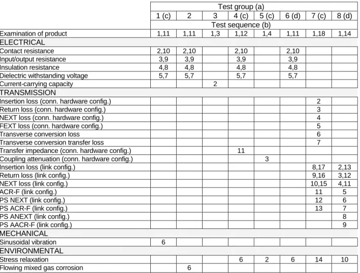
3.6 Product Qualification and Requalification Test Sequence
Test group (a)
1 (c) 2 3 4 (c) 5 (c) 6 (d) 7 (c) 8 (d) Test sequence (b)
Examination of product 1,11 1,11 1,3 1,12 1,4 1,11 1,18 1,14
ELECTRICAL
Contact resistance 2,10 2,10 2,10 2,10
Input/output resistance 3,9 3,9 3,9 3,9
Insulation resistance 4,8 4,8 4,8 4,8
Dielectric withstanding voltage 5,7 5,7 5,7 5,7
Current-carrying capacity 2
TRANSMISSION
Insertion loss (conn. hardware config.) 2
Return loss (conn. hardware config.) 3
NEXT loss (conn. hardware config.) 4
FEXT loss (conn. hardware config.) 5
Transverse conversion loss 6
Transverse conversion transfer loss 7
Transfer impedance (conn. hardware config.) 11
Coupling attenuation (conn. hardware config.) 3
Insertion loss (link config.) 8,17 2,13
Return loss (link config.) 9,16 3,12
NEXT loss (link config.) 10,15 4,11
ACR-F (link config.) 11 5
PS NEXT (link config.) 12 6
PS ACR-F (link config.) 13 7
PS ANEXT (link config.) 8
PS AACR-F (link config.) 9
MECHANICAL
Sinusoidal vibration 6
ENVIRONMENTAL
Stress relaxation 6 2 6 14 10
Flowing mixed gas corrosion 6
NOTES (a) See paragraph 4.1.A
(b) Numbers indicate sequence in which tests are performed (c) Test sequence for AMP CO Insert Cat. 6A 1x RJ45
(d) Test sequence for AMP CO Insert Cat. 6A 10/100BT & ISDN, Cat. 6A 2x 10/100BT and Cat. 6A 2x ISDN
Figure 2 4. QUALITY ASSURANCE PROVISIONS
4.1 Qualification Testing A. Sample Selection
Samples shall be prepared in accordance with applicable Instruction Sheets and shall be selected at random from current production. All test groups shall each consist of a minimum of 6 samples.
B. Test Sequence
Qualification inspection shall be verified by testing samples as specified in Figure 2. 4.2 Requalification Testing
If changes significantly affecting form, fit or function are made to the product or manufacturing process, product assurance shall coordinate requalification testing, consisting of all or part of the original testing sequence as determined by development / product, quality and reliability engineering.
4.3 Acceptance
Acceptance is based in verification that the product meets the requirements of Figure 1. Failures attributed to equipment, test setup or operator deficiencies shall not disqualify the product. When product failure occurs, corrective action shall be taken and samples resubmitted for qualification. Testing to confirm corrective action is required before resubmittal.
4.4 Quality Conformance Inspection
Applicable Tyco Electronics quality inspection plan will specify the sampling acceptable quality level to be used. Dimensional and functional requirements shall be in accordance with applicable product drawing and this specification.
Figure 3
Figure 4
Current Carrying Capacity Curve
0 0,5 1 1,5 2 2,5
0 5 10 15 20 25 30 35 40 45 50 55 60 65 70 75 80 85 90 95
Temperature (ºC)
C
u
rr
e
n
t
(A