Final Design Report
Team:
CP Check Valve
–
Team 53
Team Members:
Jessica Dent, Skylar Tusting, Alec Der Matoian
Team Contact:
[email protected]
Project Title:
Check Valve Design
Sponsor:
Zurn Wilkins
–
Paso Robles
i
Statement of Disclaimer
ii
Abstract
This report is to serve as a final design review and update to the project sponsors at Zurn Wilkins for the Check Valve Design Senior Project. The senior project team was tasked with improving upon the design of Zurn Wilkins’ backflow prevention assembly for small diameter pipes by reducing the pressure loss created by the check valves within the double check backflow assembly. The information contained in this report builds off the information contained in the Critical Design Report (CDR), as well as feedback and further investigation suggested during an Intermediary Design Review. Based on conclusions from the CDR, our team settled on developing one main design, referred to as the double-disk check valve. The goal of this design is to use the mechanical advantage of two actuating half-disk poppets connected to a central hinge to allow for greater cross-sectional flow area during open flow conditions, reducing pressure loss for each check valve.
This report explains the decision behind the double-disk design and includes discussion on design alternatives that were considered. Our team provides analysis of data defending the final design
direction, manufacturing plans, material selections, anticipated costs, and the results of iterative testing of various prototypes. Prior to March 18th, 2020, our team anticipated using the remaining months of
the project to iterate upon the double-disk design through prototyping and testing at Zurn Wilkins’ wet lab facility. Due to the COVID-19 pandemic, the team has needed to modify the scope of the project. The double-disk design was instead finalized using analytical methods. However, due to health restrictions the team was not able to manufacture a model of this proposed design. We were able to work with our sponsor at Zurn to have one final prototype tested to help validate our models. The final design
iii
Contents
List of Figures ... vi
List of Tables ... vii
1.0 Introduction ... 1
2.0 Background ... 3
2.1 Existing Designs and Patent Research... 3
2.2 Patent Research ... 6
2.3 List of Applicable Industry Codes, Standards, and Regulations ... 7
3.0 Objectives ... 8
3.1 Problem Statement ... 8
3.2 Boundary Diagram ... 8
3.3 Customer Needs ... 8
3.4 Customer Wants ... 9
3.5 Design Considerations... 9
3.6 Customer Needs & Wants Summary ... 9
3.7 Quality Function Deployment Process ... 10
4.0 Concept Development ... 12
4.1 Ideation Processes ... 12
4.2 Initial Concept Sketches ... 14
4.3 Concept Selection & Weighted Decision Matrix ... 16
4.4 Concept CAD & Preliminary Calculations ... 17
4.5 Risks, Challenges, and Unknowns ... 22
4.6 Preliminary Design Paths ... 22
5.0 Final Design as of CDR ... 23
5.1 Progressing the Double-disk as Final Design ... 23
5.2 Preparing the Double Disk to Meet Specifications ... 26
5.2 Configuration of the Double Disk – Pre CDR ... 27
5.3 Safety, Manufacturing Considerations, & Cost ... 29
5.4 Final Double Disk Design Preview – Post CDR ... 30
6.0 Completed Manufacturing & Testing ... 31
6.1 Procurement ... 31
6.2 Manufacturing Operations ... 32
iv
6.4 Outsourcing ... 37
6.5 Suspension of Manufacturing and Testing Operations ... 37
7.0 New Project Scope & Results ... 37
7.1 New Problem Statement & Objectives ... 37
7.2 Original Design Verification Plan ... 38
7.3 Final Prototype Design ... 43
7.4 Test Data and Numerical Analysis ... 44
7.5 CFD Simulation Results ... 47
7.6 Proposed Final Design ... 49
7.8 Additional Research – Sealing Methods... 57
8.0 Project Management ... 66
8.1 Post CDR Approach – Meeting Engineering Specifications ... 66
8.2 Completed Deliverables – Modified ... 67
8.3 Reflection of Project Management Strategies ... 67
9.0 Conclusions & Recommendations ... 69
9.1 Key Results ... 69
9.2 Future Recommendations ... 69
9.3 Acknowledgments ... 70
v
Appendix O – CFD Results ... O
HOUSING_BASELINE_1 ... O Summary ... O Design 1 ... O Decision Center ... O V6_45 ... O Summary ... O Design 1 ... O Decision Center ... O V6_90 ... O
Summary ... O Design 1 ... O Decision Center ... O V6_MOTION ... O Summary ... O Design 1 ... O
vi
List of Figures
Figure 1. Cross Section of a Double-Check Backflow Preventer ... 1
Figure 2. Swing Check Valves (Crane) ... 3
Figure 3. Tilting Disc Check Valve (Crane) ... 4
Figure 4. Dual Disk Check Valve (US Valve) ... 4
Figure 5. Lift Check Valves ... 5
Figure 6. Inline Spring Check Valve (US Valve) ... 5
Figure 7. Dual Action Check Valve, Adapted from US 8,875,733, Fig. 6C ... 6
Figure 8. Variable Opening Force Check Valve. ... 6
Figure 9. Flapper Check Valve patent design. ... 7
Figure 10. Boundary Diagram Sketch ... 8
Figure 11. Sketch of aperture-inspired check valve design ... 14
Figure 12. Concept sketch of double-disk design. ... 15
Figure 13. Sliding Rail Sketch ... 16
Figure 14. Counter-Weight Swing Check Sketch ... 16
Figure 15. Isometric views of the top concept designs. ... 18
Figure 16. Adaptation of the double-disk design CAD... 19
Figure 17. Camera aperture-inspired design CAD. ... 19
Figure 18. Visual of the aperture valve in closed and open positions. ... 20
Figure 19. Non-linear linkage design. ... 20
Figure 20. Conceptual CAD of the non-linear spring driven check valve. ... 21
Figure 21. Comparison of Performance of (as of 2/29/2020) Latest Prototypes to Zurn 350XL Baseline . 23 Figure 22. Sectioned View Showing Restricted Cross-Sectional Area of Split Inline ... 24
Figure 23. Close-Up Showing Central Flow Channel of Split Inline ... 25
Figure 24. Sectioned View Showing Increased Cross-Sectional Area of Double Disk ... 26
Figure 25. Force vs Stroke Graph Illustrating Force of Buckling Spring ... 27
Figure 26. Isometric Sectional View of Double Disk Valve Assembly ... 28
Figure 27. Cross-Sectional Overhead View of Double Disk ... 29
Figure 28. New Features of Proposed Final Design ... 30
Figure 29: Example of poppet seals cut using the ME machine shop laser cutter... 32
Figure 30. Cutting steel pins to length ... 33
Figure 31. Hinge seals cut to length and placed on hinge ... 34
Figure 32. Cut O-rings to length for dovetail grooves ... 34
Figure 33. Final prototype with pins inserted through springs and poppets ... 35
Figure 34. Hing and poppets placed inside the check frame ... 35
Figure 35. Final prototype check valve, fully assembled ... 36
Figure 36. Final check prototype inserted into backflow housing for testing ... 36
Figure 37. Pressure loss test stand PFD ... 39
Figure 38. Inlet isolation butterfly valve (3) ... 40
Figure 39. Magnetic flow meter (4) ... 40
Figure 40. Digital pressure gauge (5) ... 41
Figure 41. Test stand ... 41
Figure 42. Gate valve for flow control ... 42
vii
Figure 44. Test data to verify expectations... 44
Figure 45. Split Inline Poppet: Diffuser test data ... 45
Figure 46. Double Disk V4 30° test data ... 45
Figure 47. Test Results comparing v6 to Zurn Design ... 46
Figure 48. Results of initial CFD ... 47
Figure 49. Flow rate ramp function ... 47
Figure 50. V6 45° static pressure gradient ... 48
Figure 51. V6 90° static pressure gradient ... 48
Figure 52. V6 motion elements pressure gradient ... 49
Figure 53. Final proposed design ... 50
Figure 54. Proposed double-disk check final design ... 50
Figure 55. Groove detail on check spacer ... 51
Figure 56. Groove detail on modified check housing ... 51
Figure 57. Threaded pin ... 52
Figure 58. Housing with threaded holes ... 52
Figure 59. Asymmetrical Poppet ... 53
Figure 60. Top view of asymmetrical poppet disks ... 53
Figure 61. Detail view of dovetail groove ... 54
Figure 62. Old prototype with spring ends inserted within the disks ... 55
Figure 63. Close-Up of Sealing interface of Poppets. Adapted from Figure 54. ... 57
Figure 64. Close-Up Illustrating Inline Check's Flat Sealing Surface. Adapted from Figure 23. ... 58
Figure 65. PBM Adjust-O-Seal Example. Adapted from PBM Valve Solutions ... 59
Figure 66. Close-Up Illustrating Threaded Pin Holes. Adapted from Figure 52. ... 60
Figure 67. Cross-Section of Self-Gripping Seal /Gasket ... 61
Figure 68. Cross-Section of Dovetail Gland with O-Ring Seal ... 62
Figure 69. Representation of Compression Set. Adapted from Apple Rubber Products. ... 63
Figure 70. Extrusion Limits of Various Hardness O-Rings ... 64
Figure 71. Dovetail Glan Dimensioning Guide. Adapted from Apple Rubber Products ... 65
List of Tables
Table 1. Summary of Customer Wants, Needs, and Design Considerations ... 9Table 2. Engineering Specifications Table... 10
Table 3. Flow Resistance Brainwriting Results ... 13
Table 4. Flow Force Brainwriting Results ... 13
Table 5. Entry/Exit Shape Brainwriting Results ... 13
Table 6. Decision Matrix comparing top conceptual designs. ... 17
Table 8. Summary of Project Budget for Final Design ... 31
Table 9. Overview of Part Manufacturing Processes ... 56
Table 10. Expected Actions to Satisfy Engineering Specifications ... 66
1
1.0 Introduction
The purpose of this report is to present the final design for sponsor approval by the senior project team assigned to the Check Valve Design challenge for Zurn Wilkins in Paso Robles, CA. An overview will be presented on topics discussed in the preliminary design review, including an explanation of the
objectives, conceptual prototype process, preliminary design, testing plan, and design paths considered. The report includes the results of testing and analysis used in the development of the final design. This document also includes an overview of how the team managed its progress and accountability for the project.
Zurn Wilkins is a manufacturer of water and plumbing solutions, targeting commercial, industrial, and municipal markets. One of their many product groups includes water safety devices, more specifically, backflow prevention assemblies. These devices are placed in series with an existing water supply line that feed anything from single rooms in a house, to entire commercial complexes. When the flow of water is stopped or even reversed, the backflow preventer closes an internal valve that prevents any downstream contamination from traveling upstream. Figure 1 represents a cross-section view of the internals of a double-check valve.
Figure 1. Cross Section of a Double-Check Backflow Preventer
Zurn has proposed a project that aims to design a new type of mechanically actuated backflow prevention system, focusing on the check valve. The new design should improve upon existing Zurn check valve designs by minimizing pressure loss and be scalable to different diameter valve assemblies, ranging from ¼” to 2”.
In addition to offering engineering oversight, Zurn provides the team access to their “wet” testing facility. Qualities such as pressure loss, differential pressure holding, and material integrity (burst/leak pressures) can be tested in the lab. Zurn also provides the opportunity for in-house rapid prototyping via two liquid/laser 3D printers.
2
Near the end of Cal Poly’s 2020 winter quarter term, the unfortunate consequences of the COVID-19 outbreak began to affect critical operations of the campus, including learning activities and projects; off-campus travel, on-off-campus resources, and overall access to labs and facilities were eventually suspended for the remainder of the academic year. Since this project is heavily reliant upon the use experimental test results driving the critical design changes of the next prototype iteration, having no direct access to experimental testing or rapid prototyping severely undercuts this iterative testing cycle.
These impacts have prevented our team from completing this project with the deliverables anticipated at the time of presenting the Critical Design Review (CDR), which includes a fully-functioning prototype that could operate similar to a production model. The team was not able to manufacture a model that includes proper sealing and backflow prevention, which was to be tested in Zurn’s facilities.
3
2.0 Background
Any project requires sufficient knowledge of the system/environment that is involves the product or service to be provided. Multiple sources were used to research background information, patent history, and current industry device designs.
2.1 Existing Designs and Patent Research
A check valve is a valve that allows fluid flow in only one direction. There are a wide variety of check valves used in various applications, each with unique performance characteristics. Listed below are a few of the existing types of check valves and a brief description of their operation, applications, performance, and limitations.
2.1.1 Swing Check Valve
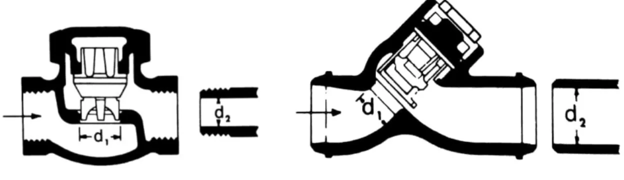
A swing check valve contains a disc that swings on a hinge or shaft. A cross-section of two styles of swing checks is shown in Figure 2. The disc swings off the valve seat to allow forward flow. When the flow is stopped, the disc swings back onto the seat to block reverse flow. Often, a lever/weight or a lever/spring combination is mounted to the disk to achieve improved performance. Although swing check valves come in various sizes, they are typically used in larger diameter lines. A common issue for swing check valves is water hammer. It can occur when the disk closes rapidly and abruptly stops the flow. This causes a surge in pressure that can result in high velocity shock waves and place a large stress on the piping in the system. [Perry’s]
Figure 2. Swing Check Valves (Crane)
2.1.2 Tilting Disk Check Valve
4
Figure 3. Tilting Disc Check Valve (Crane)
2.1.3 Dual Disk Check Valve
A dual plate or dual disk check valve has two halves of a disk that fold at the center around a common pivot or shaft. The two half plates rest on the valve seat when in the closed position. A torsion spring at the pivot point helps maintain closure when upstream pressure is lacking. The pressure loss is greatly reduced because the disc folds into a more streamlined profile thus reducing the drag, as can be seen in Figure 4. If the pressure is not high enough the valve may not fully open and have a larger pressure loss as compared to other valves. In addition to a rise in energy consumption, insufficient flow velocity can wear the valve prematurely. This can lead to issues with proper sealing, especially when used in vertical orientations were additional spring force is necessary to seal the valve against gravity. [Sotoodeh] They are also sometimes known as butterfly or wafer check valves. [2016 ASHRAE]
Figure 4. Dual Disk Check Valve (US Valve)
2.1.4 Lift Check Valve
5
Figure 5. Lift Check Valves
2.1.5 Inline Spring Check Valve
Inline spring-loaded check valves are common and have a fairly simple design. When flow enters the inlet port of the valve, it must have enough pressure to overcome the cracking pressure and the force of the spring. Once overcome, it pushes the disk open and allows fluid to flow through the valve, as shown by Figure 6. When the pressure is no longer high enough, or there is a backpressure, the spring
compresses the disc against the seal and shuts the valve. The spring and the short travel distance allow for quick reclosing time when the pressure is not sufficient. This design also helps avoid pressure surges in the line and thus prevents water hammer. They can be installed in the vertical or horizontal positions. They typically have poor pressure loss performance since the flow must overcome the force of the spring and the disk remains in the flow path.
Figure 6. Inline Spring Check Valve (US Valve)
2.1.6 Backflow Direct Dual-Action Check™
6
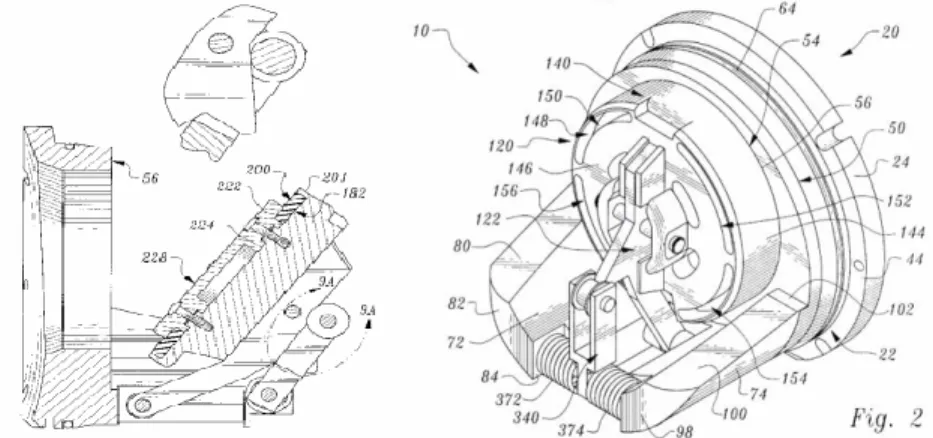
could do. Figure 7 illustrates a side view of the check valve assembly, with the valve entering the rotation phase of the stroke. (US 8,875,733)
Figure 7. Dual Action Check Valve, Adapted from US 8,875,733, Fig. 6C
2.2 Patent Research
A list of relevant patents is listed in Appendix A – Patent Table; however, there are two of these designs that we find most interesting with regards to the design challenge.
Figure 8. Variable Opening Force Check Valve.
7
Figure 9. Flapper Check Valve patent design.
The flapper check valve (6050293), shown in Figure 9, is of interest to the team because it uses the mechanical advantage of lever arms to hold the valve in a closed position. Utilizing a lever arm is a potential solution to our design problem. [Lin, Ping, and Rand Ackroyd]
2.3 List of Applicable Industry Codes, Standards, and Regulations
There are many standards, industry codes and regulations surrounding valves, backflow prevention assemblies, and check valves. We have listed some of the most relevant below. See Appendix B
–
Applicable Industry Codes, Standards, & Regulations for a more detailed explanation of each standard. Appendix C – Glossary also provides a glossary for common technical terms used in the field of backflow prevention and pipe flow.• ASME B16.34 • ASSE 1015 • CSA B64.5 • AWWA C510-17
• Cal OSHA Title 8, Subchapter 7, Group 2, Article 9, §3363(h)
8
3.0 Objectives
Due to the conditions and changes of plans caused by COVID-19, the objectives of this project have changed substantially. These changed include how much improvement to the current design was forecasted from CDR to the end of the project, and which engineering specifications were quantitatively met with the latest-developed prototype.
3.1 Problem Statement
Zurn Wilkins, a plumbing parts manufacturing company, is requesting a new check valve design that uses mechanical advantage and fluid dynamic principles to reduce pressure loss comparative to their existing products. This design must meet industry standards for water supply backflow prevention.
3.2 Boundary Diagram
The boundary diagram for this project can be seen in Figure 10. Our team’s work for this project will remain within the boundary of the valve housing in Zurn’s current product lines. We will need to consider the design’s interface with the check valve enclosure (housing), the test plugs, and the sealing surfaces connecting the check valve to the isolation ball valves on either end.
Figure 10. Boundary Diagram Sketch
3.3 Customer Needs
The main customer for this project is Zurn Wilkins. The major customer needs fall within the category of improving performance. The customer needs are as follows:
• Reduce the pressure loss: The current product has pressure loss due to the inline disc disrupting the flow path
• Maintain a static pressure differential: A minimum pressure differential between the inflow and outflow of the check valve. This requirement is crucial to the functionality of the check valve to prevent backflow.
• Mechanically driven: The check valve must open and close using only mechanical means. • Meets industry requirements: This includes flow, pressure, and safety regulations for backflow
9
o Water compliant materials: The design must be made of materials that will not rust or corrode.
3.4 Customer Wants
Customer wants are design criteria that are important to take into consideration and would improve the quality of the design. Customer wants are important for the function of the design and are considered lower priority than customer needs. The customer wants are listed below:
• Adaptable design: The design should be able to fit within backflow systems between 3/4" and 2" in diameter. The design should also be able to scale to the various standard pipe diameters within the ¾” to 2” range while maintaining proper functionality.
• Manufacturability: The ease of manufacturing the design should be taken into consideration throughout the development process. Designs that are simple and utilize conventional manufacturing techniques, such as injection molding, are preferred.
o Standard tooling: The design dimensions should follow US Customary unit standard sizes and be manufactured using standing tooling.
• Horizontal or vertical position: The valve must function properly if placed either horizontally or vertically. The closing mechanism should not be significantly affected by the direction of gravity.
3.5 Design Considerations
The following are factors to be considered during the design process, but not required for a successful product.
• Compatible with Zurn’s current design: The user should be able to swap out the new design for the existing one without making alterations to the existing valve housing or connecting surfaces. • Reduced complexity: The new design should aim for simplicity. A mechanism with less parts has
less potential to break and is easier to maintain.
• Cost comparable: Our team’s design should aim to be comparable in costs to Zurn’s current design. This means no exotic materials or uncommon manufacturing processes should be used.
3.6 Customer Needs & Wants Summary
The customer needs, wants, and design considerations are summarized in Table 1. Many of the listed items have some interdependence. The customer needs will be prioritized for the final design.
Table 1. Summary of Customer Wants, Needs, and Design Considerations
Customer Needs Customer Wants Design Considerations
Reduced pressure loss Adaptable design Compatible with Zurn’s current design
Maintains static pressure
differential Designed for manufacturability Reduced complexity Mechanically driven Adapt design of DC to RP setup Cost comparable Meets industry standard
(As listed in Section 2.3)
10
3.7 Quality Function Deployment Process
To better define the problem being addressed in this project, our team used a Quality Function Deployment (QFD) process. The QFD method is used to translate the customer needs, wants, and thoughts into engineering specifications which can be measured and evaluated. Our team utilized a QFD tool called the House of Quality which can be seen in Appendix D – House of Quality.
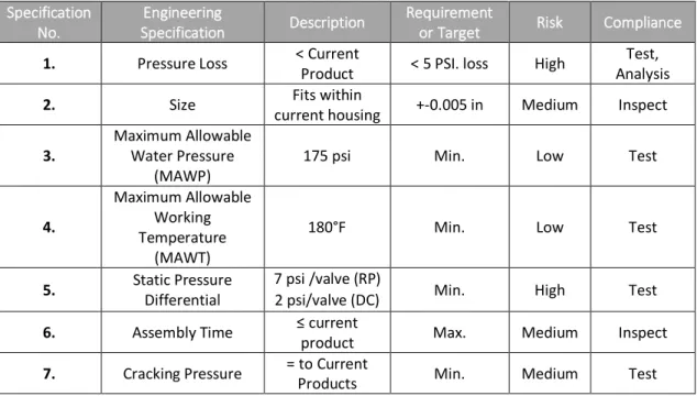
From our QFD process, we have found engineering specifications to meet each customer need. The team was able to match the customer wants and needs either directly or indirectly through the specifications listed in Table 2.
Table 2. Engineering Specifications Table
Specification No.
Engineering
Specification Description
Requirement
or Target Risk Compliance
1. Pressure Loss < Current
Product < 5 PSI. loss High
Test, Analysis
2. Size Fits within
current housing +-0.005 in Medium Inspect
3.
Maximum Allowable Water Pressure
(MAWP)
175 psi Min. Low Test
4.
Maximum Allowable Working Temperature
(MAWT)
180°F Min. Low Test
5. Static Pressure
Differential
7 psi /valve (RP)
2 psi/valve (DC) Min. High Test
6. Assembly Time ≤ current
product Max. Medium Inspect
7. Cracking Pressure = to Current
Products Min. Medium Test
The engineering specifications have associated risks, from low to high. High risk specifications are considered the most challenging for the team to complete. Reducing the pressure loss and holding the static differential requirement is critical for the design to be successful. In the compliance category, the method of verifying each specification is listed. “Test” means formal testing will be done, likely at Zurn’s facility. “Inspect” will be a go/no-go compliance check. “Analysis” means the specification will be investigated through computer programs or studies such as FEA and CFD.
11
of lower priority than many of the other specifications. The cracking pressure specification refers to the amount of pressure differential needed to change the valve from its normally closed state to the open state. This is an important value for piping system designers and needs to be equal to the cracking pressure required for Zurn’s current in-line spring check valve.
The results of the QFD predict that the most important characteristics of the project are as follows: • Maintain Desired Cracking Pressure (@ 18% Relative Weight [RW] of QFD)
• Minimize # of components (@ 14% RW) • Reduce Pressure Loss (@ 13% RW) • Reduce Assembly Time (@ 14% RW)
It should be noted that after further discussion with Mr. Yale, the objectives of reduced assembly time and component count/complexity, that appear to fall under the category of “Design for
12
4.0 Concept Development
This section serves as an overview of the ideation, concept prototyping, and design selection progress. In this section, the project team provides a list of the ideation methods used, along with examples of some of the concept sketches and prototypes developed. Idea refinement and selection was performed using a design matrix, and preliminary rough CAD models were produced to begin exploring some of the selected design elements. After the Preliminary Design Review the team decided to pursue a two different concept designs to test and compare the effectiveness of each model. These two design paths and their performance will be discussed.
4.1 Ideation Processes
The following section describes the several ideation methods the team used to generate large amounts of simple, isolated concepts that could later be developed or combined. By the end of the ideation period of the design cycle, decision-making tools such as a weighted decision matrix were used to select the most viable designs for further refinement.
4.1.1 Functional Decomposition, Brainstorming, & Brainwriting
To make use of the goals developed during the Scope of Work in terms of check valve operation, our team used functional decomposition sessions to break down the goals of the project into manageable aspects that were targeted individually. The broken-down characteristics included minimizing activation force, changing the entry/exit shape, and reducing flow resistance.
After functional decomposition was completed, a series of brainstorming and brainwriting sessions were conducted to further develop the design challenges identified. These exercises included the production of sketches that attempt to solve the design challenges listed.
Since the team consists of 3 members, the commonly-used “Brainwriting 6-3-5” method, meaning 6 members, producing 3 ideas each, in 5 minutes, was adapted to 3-3-5. Each Brainwriting table took a main function from the functional decomposition results as the problem statement. Then, each member provided ideas on how to solve or improve such issues. After several Brainwriting sessions were
conducted, some of the recurring ideas or concepts were used in formulating the design options listed within our design matrix, detailed in Table 6.
In Table 3, team member brainwriting results are provided for attempting to “Reduce Flow Resistance.” Pressure loss reduction is important to the overall success of the valve design since pressure loss is considered by the industry to be a critical performance indicator.
13
Table 3. Flow Resistance Brainwriting Results
Problem: How to Reduce Flow Resistance?
Member: Idea 1: Idea 2: Idea 3:
Jess Conical Valve Gate Valving Aperture Valve
Skylar Smooth contouring Origami Valve Laminar flow
production Alec Smooth material Channeling flow Use of internal airfoils
In Table 4, team member brainwriting results are provided for attempting to “Minimize the force required for open-valve flow.” All energy used to maintain the open state of the valve after cracking pressure has been exceeded is considered wasted energy. Thus, allowing the water to maintain as much energy as possible during open flow conditions is an important goal to meet. Here, a compound or multi-link spring system proved popular. The concept would involve using multiple springs to allow for varying spring forces at different times during the valve stroke. That is to say, the valve can experience a multitude of spring force constants as distance traveled changes. This concept was further refined to be operable in a translational, or rotational nature. Further visualization of these two design paths is presented in Figure 19 and Figure 20.
Table 4. Flow Force Brainwriting Results
Problem: How to Minimize Open Flow Force?
Member: Idea 1: Idea 2: Idea 3:
Jess Self-closing orifices Rail-slider Multi-link pivot
Skylar Ratcheting system Use gravity Mechanical Advantage
Alec Locking pins Compound spring Torsional latch
In Table 5, team member brainwriting results are provided for attempting to “Change the Entry/Exit Shape of the Valve Body.” This functional decomposition result was thought to be important since reducing the cross-sectional area that the water flow “sees” in its flow path translates to greater flow capacity and lower pressure drop. The brainwriting results pointed to designs that involved either “flipping” the valve via a system of rails & guide channels, or a multi-face valve, such as a double-disk valve or butterfly valve.
Table 5. Entry/Exit Shape Brainwriting Results
Problem: How to Change Entry/Exit Shape?
Member: Idea 1: Idea 2: Idea 3:
Jess Aperture design Rotating Valve seat Origami Valve
Skylar double-flap Origami Valve Overlapping valve flaps
Alec Non-constant orifice sizes
Compound Movement Valve
14 4.1.2 Concept Prototyping Session
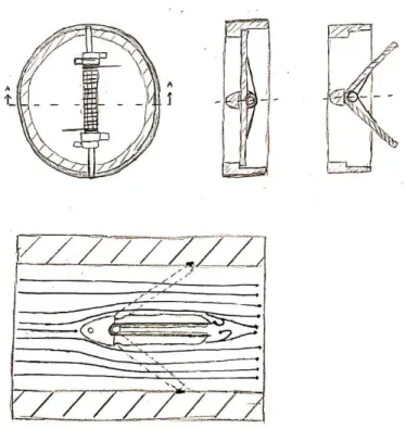
The figures presented in this section are the result of a concept design session using craft and low-cost materials. The purpose of this exercise was to take the large number of design ideas and generations from the ideation sessions described in Section 4.1.1 and produce low-resolution concept models that could allow for better visualization and description of a certain idea. These models serve as
representations of isolated functions of what the final design might entail.
4.2 Initial Concept Sketches
From our initial ideation sessions, we made more detailed sketches of our top ideas. The top ideas the team selected to detail out were the Folding Aperture, Modified Double-Disk, Sliding Rail, and the Counter Weighted Lever Swing. These designs were selected because they either will reduce the drag of the closing mechanism or they will take less force to hold open than the current Zurn design. These designs all have significantly different forms and their effectiveness of their ability to reduce pressure loss is best determined in real test conditions.
4.2.1 Aperture Check Valve
The inspiration for this valve, shown in Figure 11, was a camera aperture mechanism. The primary benefit of this design is that when it is in the full-open position there is no obstruction of flow. The valve would have losses close to that of an equivalent length of pipe, assuming the entrance and exit regions of the valve line up with the internal diameter of the adjoined piping. The difficulty of this design is determining how to have the valve actuate from a closed to an open position based on pressure and flow direction using mechanical elements. Another main concern is that sealing with multiple elements could be difficult. Through prototyping we found that finding a material that properly seals while allowing the sliding of the aperture elements is difficult to find. Similar ideas we considered involved folding mechanisms akin to origami. Upon further investigation, we decided most of these were variations of the aperture or double-disk designs.
15 4.2.2 Modified Double-disk Check Valve
This design is based on the existing double-disk check valve design. The details of operation and functionality of this valve were previously described in Section 2.3.3 and are shown in Figure 12. The primary difference in this design as compared to a standard double-disk wafer check valve is that it could utilize a compound spring mechanism. The compound spring mechanism would allow the holding pressure of the valve to be reduced as the valve opens more. Zurn has an inline check valve that utilizes a set of rollers and spring bar to create a compound spring element. An adaption of this existing design could be used on a double-disk check valve combining the positive aspects of each design
Figure 12. Concept sketch of double-disk design.
4.2.3 Sliding Rail Check Valve
16
Figure 13. Sliding Rail Sketch
4.2.4 Counter Weighted Lever Swing Check Valve
This design is based on a typical swing check valve with the addition of a lever arm with a weight. The lever arm and weight help offset the center of gravity of the swing assembly. By pushing the center of gravity further away from the point of rotation we take advantage of the lever arm. As the valve opens the weight and thus the center of gravity shifts closer to the point of rotation reducing the amount of torque. This, in turn, reduces the amount of force required to hold the valve open and reducing pressure loss. Figure 14 shows this aspect of the design.
Figure 14. Counter-Weight Swing Check Sketch
4.3 Concept Selection & Weighted Decision Matrix
17
Table 6. Decision Matrix comparing top conceptual designs.
Criteria Weight
Design Option
Aperture Double-Disk Mod
Nonlinear
Link Rail Slider Lever Swing Score Total
Score Total Score Total Score Total Score Total Minimize
Open-State Force 4 3 12 3 12 5 20 3 12 5 20
Minimize
Component # 2 1 2 4 8 2 4 3 6 3 6
Reduce Pressure
Loss 5 5 25 4 20 3 15 3 15 4 20
Reduce Assembly
Time 2 1 2 3 6 1 2 3 6 2 4
Ease of Design
Scalability 3 3 9 4 12 3 9 3 9 2 6
TOTAL: 50 58 50 48 56
The outcome of the matrix ranked the designs as follows: double-disk adaptations and counterweighted swing check as most likely to meet the customer needs. These were followed by the folding aperture, Non-linear linkage, and sliding rail. The double-disk and counterweighted check valve designs are ranked best is because they are expected to reduce pressure loss more than other designs since they are similar to patents and conventional designs. Another key criterion ranks how well each design might minimize the force required to hold the valve in its open state. This favored the designs that utilized mechanical advantage. One criterion that was not explicitly considered in Table 6 is the consistency of sealing for each valve. This can be speculated however the team believes this will be best understood through reliability testing for each design. The designs that were chosen for modeling are the double-disk adaptation, the non-linear linkage, and the folding/aperture design. These designs were chosen for prototyping because we wanted to better understand how they would function.
4.4 Concept CAD & Preliminary Calculations
18
Figure 15. Isometric views of the top concept designs.
4.4.1 Modified Double-Disk
The concept CAD model for the double-disk adaptation is shown in detail in Figure 16. The benefit of this design is that it nearly eliminates all obstruction of flow when it is open. Another benefit is the valve’s symmetric nature, allowing for streamlined manufacturing and component design over non-symmetrical design. The valve requires only one degree of freedom, rotation about the axis of the linkage pin, reducing the overall mechanical complexity and risk of premature mechanical failure. One of our adaptations is to start the disks at a steeper angle than is conventional to decrease the amount of travel necessary to reach a fully open state. The diameter of the disks, when spread out, is larger than the internal diameter of the pipe, ideally minimizing sealing issues. This was tested at a later phase of the design process. The purple disks and gray central mount would be made of conventional plastic and the pin through it all would be a corrosion-resistant metal. This design would meet all customer
requirements if standard materials are used and the proper spring rates are selected. The double-disk design is known in industry to have lower pressure losses than an in-line spring design.
To meet the closing pressure for the double-disk the spring, each half-disk for this cross-sectional flow area would require a spring rate of k =2.22lb/in. In comparison, Zurn’s current in-line check has a spring force of k = 4.43 lb/in. An advantage of the double-disk is that each spring would be smaller and
19
Figure 16. Adaptation of the double-disk design CAD.
4.4.2 Aperture Style Design
The next design was inspired by the way that rotation moves the pieces of the camera aperture away from the closed position. The aperture-style check valve can be seen in Figure 17. The benefit to this design is that it could fully remove any obstruction to the flow path. However, it is also complicated and there is more room for issues to arise with the high number of parts. The valve would meet all
engineering specifications and customer requirements, especially those regarding pressure loss. The only concern with meeting specifications is that the assembly time would be high and the mechanism to regulate the cracking pressure is not fully defined yet.
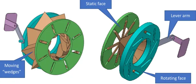
Figure 17. Camera aperture-inspired design CAD.
Pivot point
Valve disk
Lever arm Static face
Rotating face Moving
20
The valve rotates the orange “wedges” along the slots by turning the blue disk. The mechanism for closing the blue slotted disk is not yet fully defined but is expected to utilize a lever arm that is pushed open there is enough pressure differential to reach the desired cracking pressure. There would likely be a torsional spring to apply the closing force on the valve.
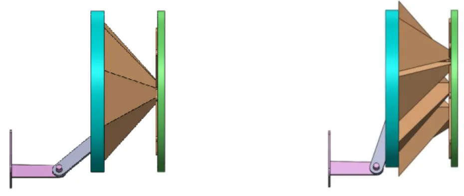
Figure 18. Visual of the aperture valve in closed and open positions.
The valve is shown in Figure 18. In the open (right) and closed (left) positions. The wedges would likely be made of a plastic with the contacting sides being coated or covered in a low-friction substance. The number of wedges and shape of the moving pieces will need to be refined through testing if this design is selected. Potential disadvantages of the moving “wedges” are custom manufacturing and the
introduction of friction between the sliding pieces. 4.4.3 Non-Linear Linkage Designs
A third major design consideration is the use of a non-linear spring force linkage. These designs are specifcally made with the intent to reduce the amount of force required to hold the valve in the open position after the required cracking pressure has been met. This should reduce the amount of energy lost to holding the valve open. The non-linear design meets the required customer specifications and would specifically excel at the criterion of minimizing the force needed to hold the valve open. This is achieved using non-linear mechanisms such as the dual spring assembly concept shown in Figure 19.
Figure 19. Non-linear linkage design.
1st Spring
2nd Spring Locking
21
Since the springs are in series, the spring rate can be changed depending on which springs are allowed to actuate. As the stroke of the first spring reaches the maximum, a locking mechanism (detailed blue in Figure 19) is pushed out of the way, allowing the second spring to compress in series with the first. One disadvantage of this concept is that the assembly containing the springs would most likely be positioned directly behind the check valve. Having this large volume obstruct the flow path can potentially cause poor pressure loss results. However, this increase in flow resistance could be remedied if coupled with a valve design that changes its aspect ratio as the valve stroke is completed (such as the double-disk valve collapsing the cross-sectional area of its valves in Figure 16).
Another conceptual design that falls within the non-linear category utilizes a cam and follower system. This is modeled in Figure 20. The bar shown in yellow would be a spring and the cam profile would be perpendicular to the flow.
Figure 20. Conceptual CAD of the non-linear spring driven check valve.
Like the other designs, the materials used would be plastic for the extruded parts and linkages, with non-corrosive metals used at pins and for the springs. Much of the cam design is undefined such as the integration of it to the closing mechanism of the valve. The concept of a cam that is non-linear cam is the major interest in this design. Unlike the translational version of the non-linear spring, this rotational version can be mounted in such a way that it does not impede the flow of water. A usage example of the rotational spring includes the spring assembly in Figure 20 hinged to a check disk, while affixed to the valve body in a recess in the valve walls, as opposed to being centered in the flow path. While this ability to mount the rotational spring assembly out of the water flow path allows for improved pressure loss operation, the small physical footprint of the design would introduce the added difficulty of having to manufacture smaller components and use of smaller springs.
4.4.4 Preliminary Calculations
The introduction of a secondary spring in series requires knowledge of each spring rate and the combined spring rates. To meet the desired cracking pressure of the valve of 2 psi, and given a stroke length of 2 inches which is typical of a 2.5” diameter swing check valve, a spring constant of 0.814 lbf/in would be necessary for each spring.
Internal Cam Profile Linear Spring
22
4.5 Risks, Challenges, and Unknowns
Each of these designs has its own challenges. For example, the double-disk adaptation may have issues with sealing during backflow, while the aperture one has challenges regarding the synchronous
movement of the pieces. All designs for this project have minimal safety risks. The evaluation of safety hazards can be seen in Appendix E – Design Hazard Checklist (Updated). The major unknown variable for each of these designs is their performance regarding to pressure loss. This can be modeled using a simulation and will be tested after the top designs are prototyped. The next challenge for each of these designs is to develop rapid prototypes that represent each design well enough to be tested and
compared to Zurn’s current in-line spring check valve. The most important aspect of the first phase of this design is to select the best performing design to iterate upon later in the design process.
4.6 Preliminary Design Paths
23
5.0 Final Design as of CDR
The final design for our project progressed the double-disk design as far as possible, given the abrupt end to iterative testing and re-design capabilities from the impact of the COVID-19 outbreak.
This final design section will explore the final changes made to the current double-disk model, how our team expects these changes to meet project specifications, a detailed description of the most current double-disk assembly, and considerations of safety, cost, and manufacturing.
5.1 Progressing the Double-disk as Final Design
At the time of submitting the Critical Design Review, our final design path consisted of using the most current test data at the time to justify selecting the double disk as the final design.
Figure 21 is a compilation of our team’s test data from February 27th, 2020 at the Zurn Wilkins Paso
Robles test facility. Three pressure drop curves are plotted, showing performance results for the split inline, double disk design as of CDR (without a spring), and a baseline for the Zurn 350XL inline check (without a spring). The smaller-sloped trendlines show ultimately lower values of pressure drop, meaning a better performing valve.
Figure 21. Comparison of Performance of (as of 2/29/2020) Latest Prototypes to Zurn 350XL Baseline
0 1 2 3 4 5 6 7 8 9 10 11
0 10 20 30 40 50 60 70 80 90 100 110 120 130 140
P
re
ssur
e
D
rop
[P
SI
]
(L
ow
e
r
is
Be
tt
e
r)
Flow Rate [GPM]
Prototype Testing - Comparison to 350XL (Unspringed)
Zurn 350XL Inline - Unspringed Split Inline - Unspringed Double Disk - Springed - 30 deg Split Inline consistently maintains higher
pressure drop across large range of flow rates
Indicates geometry-restriced flow
24
There are a couple key takeaways from the data presented in Figure 21:
• The best-performing iteration of the split inline (orange curve) does not at perform better than the baseline performance of the 350XL check valve.
• The difference in pressure drop between the split inline and 350XL appear to be linear for a large position of flow rate.
• The sprung double disk appears to perform better than the split in-line with no spring at high flow rates, starting at approximately 86 GPM.
The results from 2/27/2020 testing also included testing a variety of different poppet geometries. The resulting data indicated that with the current geometry the split inline cannot surpass the 350XL in performance, regardless of flow rate. By analyzing the fact that the difference in pressure drop between the split inline and the 350XL is fairly constant for a considerable range of flow rates, the conclusion has been made that this decrease in performance is inherently due to the constricting nature of the valve’s geometry, where any benefit made by producing a central flow cavity in the poppet cannot overcome the consequence of reducing the inlet cross-sectional area. Figure 22 and Figure 23 help illustrate the areas of concern regarding this issue with the split inline.
Figure 22. Sectioned View Showing Restricted Cross-Sectional Area of Split Inline
Center conical cover reduces inlet
25
Figure 23. Close-Up Showing Central Flow Channel of Split Inline
The results from testing presented in Figure 21 confirm that out of the various designs that our team developed throughout the project, the double disk proved to have the greatest potential of achieving the engineering specifications defined in the scope of this project, most importantly including pressure loss reduction.
5.1.3 Design Advantages of the Double Disk
By revisiting the established engineering specifications of this project and constructing a new Pugh Matrix (Appendix F – Revisited Final Design Decision Matrix (Pugh Matrix)), our team determined there was enough support to continue forth with the double disk design. The driving factor of this decision was that the valve must first and foremost be able to reduce pressure loss comparative to competing products.
The double disk has a few key advantages inherent to its design that will hopefully overcome the issues encountered by the split inline in terms of performance:
• The overall frame of the double disk allows for a larger inlet area to the valve, compared to the restriction in diameter that the valve seat caused in the split inline.
• The disks of the valve actuate backwards, away from the oncoming flow. This produces an effectively smaller aspect ratio of the valve as the flow increases.
• The disks can be seated at varying angles, which can allow for our team to determine what angle of valve seating is advantageous to pressure loss performance.
Figure 24 illustrates the current geometrical advantage of the double disk valve. Note that the valve does not restrict the inlet diameter unlike the split in-line with the valve seat (seen in green in Figure 22). However, as of CDR the team had not designed the double disk to meet all engineering
specifications, such as sealing, spring subassemblies, and hinge design. Central flow channel cannot
26
Figure 24. Sectioned View Showing Increased Cross-Sectional Area of Double Disk
5.2 Preparing the Double Disk to Meet Specifications
As noted, the double disk has so far proven to be capable of enhanced pressure drop performance over the baseline 350XL valve. After CDR, our team developed a timeline for the final 10 weeks of the project to ensure the double disk will satisfy other engineering specifications not yet verified.
5.2.1 Improving Central Hinge & Angle of Disks
The current design of the double disk hinge has so far sufficed in testing and dynamic operation. However, an improved design of the central supporting arm and connecting hinges will lead itself to improved sealing capacity and ability accept a wider range of springs for further testing iteration. Furthermore, the angle of the disks when fully seated or closed, can play a role in how the valve responds to flow rate changes, and consequentially, performance in pressure drop. By conducting further iterations of modeling and CFD testing, our team anticipates selecting a disk angle that will benefit its pressure drop performance. Based on the results of CFD analysis, the final design uses a valve seat that is perpendicular to the flow direction. This is further discussed in Section
Double Disk’s ability to
27 7.5 CFD Simulation Results.
5.2.2 Sealing, Spring Forces, & Dynamic Operation
Arguably, the most difficult aspect of adopting the double disk will be to ensure that the valve is able to seal fully to prevent backflow according to proper test standards and guidelines such as USC FCCCHR. Our team needed to progress a design that ensures proper sealing while not compromising improved performance of the valve. The sealing performance of the final valve was not able to be tested due to COVID-19 restrictions, however the team proposed sealing designs that followed standard O-ring compression practices.
The manner in which the double disk provides counterforce or returning-force to itself via springs is a major factor in how the valve performs under dynamic flow conditions. One approach our team is considered was the use of a buckling spring mechanism. The premise of this device is to provide a discontinuous spring force curve, while controlling the stroke distance at which this discontinuity in force occurs. Figure 25 illustrates such a mechanism providing nonlinear resistive force dependent upon the stroke distance of the spring. In this case, the stroke is the compression distance of the spring.
Figure 25. Force vs Stroke Graph Illustrating Force of Buckling Spring
The team was unable to test any buckling springs, however we did briefly look into the mechanism prior to CDR. The challenge regarding implementing buckling springs in a double-disk design is that current buckling springs used in industry are of linear nature, where the resistive elements used in the double disk have so far only been of torsional nature.
5.2 Configuration of the Double Disk
–
Pre CDR
Figure 26 and Figure 27 shows the Pre-CDR configuration of the Double Disk in a double check assembly, meaning that two individual checks are placed within the same valve housing. Annotations are provided to mirror the names of the components as seen in the Indented Bill of Materials (See Appendix G –
Indented Bill of Materials).
28
In the configuration as of CDR, the double disk valve assembly contained 6 different part groups/sub-assemblies:
• Check Frame: Provides a structural component for smaller components to be housed in • Hinge: Main supporting structure that connects valve disks to the check frame
• 3/32” Pins: Metal pins that locate the valve disks concentrically to the check frame • Torsional Spring: Resistive force element that provides a returning force to the check
disks
• Poppet Disk: Two of these disks are the elements that prevent backflow through the valve during no-flow conditions.
• Sealing Components (Sub-group): Various components (O-Ring, Seat Seal, etc.) that allow for complete sealing of the valve during no-flow conditions.
Figure 26. Isometric Sectional View of Double Disk Valve Assembly
Backflow Housing 1-1/4” to 2”
Check #1 Frame Check #2
O-Ring Check #2
Poppet Disk (1 of 2)
29
Figure 27. Cross-Sectional Overhead View of Double Disk
5.3 Safety, Manufacturing Considerations, & Cost
Since the cost of transitioning a check valve design from pre-production and rapid prototyping into small-volume runs with custom-manufactured components can be in the range of tens of thousands of dollars, which drastically over exceeds the provided budget for our project, our team plans to source materials and prototyped components through Zurn vendors and companies specializing in prototype manufacturing and small-batch production. Section 6.0 Completed Manufacturing & Testing for further details this anticipated manufacturing strategy, along with other information detailing the assembly of the current double disk valve.
As for safety and hazard considerations, a Failure Modes & Effects Analysis (FMEA) and Design Hazard Checklist (Presented in Appendix H – Failure Modes & Effects Analysis (FMEA) & Appendix E – Design Hazard Checklist (Updated), respectively), detail the possible hazards and points of failure of our check valve design. The FMEA shows points of failure being similar to those of industry-current check valves, and there are no outstanding issues indicated within the hazard checklist. In other words, there are no novel hazards or failure points that our team or Zurn must consider when prototyping, manufacturing, or testing our designs.
Despite the fact that our current prototypes have been developed using rapid prototyping methods (SLA printing, our team still presents a package of technical drawings for the components involved in the current double disk design (See Error! Reference source not found.).
The drawings are meant to take advantage of Geometric Dimensioning and Tolerancing (GD&T) to specify critical surfaces and curvatures of the parts. For example, any mating surfaces that involve use of the stainless steel rods must be located precisely to prevent unnecessary binding from through-hole misalignment. Additionally, any seal surfaces must be manufactured to a specified surface
Check #2 Torsional Spring Check #2
3/32” Pin
(1 of 3)
30
finish/roughness so as to avoid premature valve/seal separation. Within the frame, the outer support structure must be concentric so as to fit within the existing Zurn 350 XL valve body. Cylindricity of the frame is also a concern, since any major tilt in the geometry in the check valve subassembly will cause a constant bias in shearing of the water when passing through the frame.
5.4 Final Double Disk Design Preview
–
Post CDR
After in-person testing and any project-related visits to Zurn’s facilities ceased in mid-March 2020, the corrected scope and objective of the project pushed for one final design iteration of the double disk model. Figure 28 is a rendered isometric view of the final design proposal for the double disk. A few of the major design changes/updates compared to the Pre-CDR design are highlighted:
• Modifications to the interior geometry of the valve housing
o A slotted valve spacer (seen in purple) is used to locate the two valve assemblies in relation to each other, as opposed to relying on interior grooves in the valve housing to locate each of the 2 check valve assemblies individually. The valve spacer also serves as a sealing surface for the upstream check
o Each valve assembly’s valve seat/hinge is now mechanically fastened in place via a threaded pin that protrudes through the wall of the valve housing. This change enhances structural integrity and sealing capability of the valve
o An O-ring is the sealing component for the interface of the valve hinge (seen in yellow) and the interior wall of the valve housing. This is an improvement in sealing capability over the previous design
• Dovetail glands are used in addition to a sealing medium (partial O-ring or gasket material) to seal the interface between the valve hinge (seen in yellow) and the poppets (seen in orange)
Figure 28. New Features of Proposed Final Design
Upgraded Hinge/Valve
Seat Design
Threaded Pin Inserted Through
Valve Housing Slotted Valve
Spacer
Housing Interface O-Ring
Dovetail Gland Seat Interface
31
Detailed design justification, description of operation, and assembly views involving the changes made in the final proposed design will be provided in Section 7.6 Proposed Final Design.
6.0 Completed Manufacturing & Testing
Due to the nature of this project, the iterations leading to the final design were initially done by using 3D printed models at Zurn’s facility. These printed prototypes were tested until a design conclusion was reached. Since the team was not able to continue testing during the final months of the project, the valve design was determined using the conclusions from completed testing and further analysis. The team developed a manufacturing plan that could be used for the full-scale manufacturing of these valves since no physical prototype of the final design was permitted to be built.
6.1 Procurement
Most of the components for this design are intended to be custom-made from Delrin 150. This material was selected because of its resistance to warpage when submerged in water, and its capability to be both injection-molded and post-machined. Delrin is also a common material for valve components in industry. The check valve hinge, poppet disks, and spacer will be manufactured through a combination of manual and CNC machining.
For a new valve design, Zurn Wilkins typically works with their current vendors to develop all procurement and manufacturing plans. Since the team was not able to manufacture a final valve, all procurement costs summarized in Table 7 are rough estimates for full-scale manufacturing. Many of the custom parts costs are estimates based on costs of similar parts currently produced by Zurn and by cost per weight of the material. The full budget is detailed in Appendix J – Full Budget Breakdown.
Table 7. Summary of Project Budget for Final Design
Name Description Vendor Vendor Part # Qty Cost Total Cost
Modified Backflow Housing
Nylon N72333 STHL, Black, UV Resistant. Modified from the
350XL, machined to include modifications
Zurn Wilkins 354-1A 1 $ 25.09 $ 25.09
Check Hinge Delrin 150, custom injection
molded & post-machined Protolabs ---- 2 $ 3.83 $ 7.66
Torsion Spring- Custom
Torsion Spring, 210 Degree Angle, Left-Hand Wound, 0.585" OD, 0.070" Wire Diameter, 0.5" Leg
Length, 13.083 Coils
International Industrial
Springs
---- 1 $ 10.00 $ 10.00
Poppet Disk Delrin 150, custom injection
molded & post-machined Protolabs ---- 4 $ 0.47 $ 1.88
Poppet O-ring Arcs
Buna-N O-Ring 1/16 Fractional Width, Dash
Number 040, [Zurn #040N]
McMaster-Carr 9452K128 1 $ 14.26 $ 14.26
Check O-ring Seals
Buna-N O-Ring 1/8 Fractional Width, Dash Number 237. [Zurn #273N]
McMaster-Carr 9452K166 1 $ 13.41 $ 13.41
32
3/8 Pin 3/8" 303 Stainless Steel Rod, 1 ft McMaster-Carr 8984K99 1 $ 4.54 $ 4.54
Check Spacer Delrin 150, custom injection
molded & post-machined Protolabs --- 1 $ 2.55 $ 2.55
TOTAL COST $ 83.20
The parts needed for sealing will be either be purchased from a vendor or custom manufactured. The team considered sending the custom seals to be manufactured by the company Protolabs, which our sponsor has worked with before, however due to the high initial cost of tooling for custom seals, the team decided to custom manufacture any seals that can’t be easily purchased using commercially available O-rings. All sealing grooves were adjusted to fit standard available O-rings.
The only other hardware required for the final design are a torsion spring and stainless-steel pins used in the disk hinges. The pins (3/16” and 3/8” in diameter) are made of 304 stainless steel to prevent any corrosion. For prototyping, the team used stainless steel welding filler rod, however for the final product these would be sourced from an online vendor such as Grainger Industrial or McMaster-Carr. In the final design the pins need slight modification by cutting their respective UNF threads using a manual thread die.
6.2 Manufacturing Operations
Due to the high tooling costs of injection molding and CNC machining, the process used for prototyping and testing is different compared to the final products. The process proposed for manufacturing the final design is more complicated than that used for making the prototypes. In this section our team will outline both manufacturing methods, for the prototypes and the proposed design.
6.2.1 Prototype Manufacturing
The double-disk valves that the team has tested have been rapid prototyped by 3D printing the valve pieces with Zurn Wilkins’ SLA printers. The support structure is removed, sharp edges are filed off, and the pins and springs inserted. The whole check valve is placed in Zurn’s backflow housing, and the system is ready for testing.
For the in-line check valve prototypes, custom seals made of 1/16” thick neoprene rubber were cut using one of the mechanical engineering department’s laser cutters. This method is shown in Figure 29. The seals used in the final prototype of the double disk valve were made of standard O-rings, some of which were cut to length to fit within dovetail grooves that retained them.
33
One thing to note is that the final prototype is assembled with 5 small torsion springs that match the torque requirement of the check valve. These springs do not meet the fatigue requirements of industry test standards but were adequate for the short pressure loss tests performed by our sponsor.
6.3 Assembly
One of the more frustrating aspects of the double-disk designs that have been tested so far is the length of time it takes to properly assemble the prototypes. The presence of thin features has led to parts of the valve hinge breaking during the assembly process. The assembly process for the most recently tested double-disk valve is outlined below. This prototype is referred to as the “final prototype” and is most similar to our proposed final design. Some of the breaking issues were removed by simplifying the hinge design and making the poppet disks thicker in the final design.
Since the team was not able to build the final double disk prototype in person, our senior project sponsor Mr. Yale graciously 3D printed and assembled the components for testing. The assembly procedure he used is as follows:
1. Cut the steel rod into 3 lengths of 2.75-inch segments. See Figure 30.
Figure 30. Cutting steel pins to length
34
Figure 31. Hinge seals cut to length and placed on hinge
3. Cut the medium diameter O-rings (-142) into semi-circles, as shown in Figure 32. These should match the length of the dovetail grooves on the check frame. Press these O-rings pieces into the grooves.
Figure 32. Cut O-rings to length for dovetail grooves
4. Insert a pin through the check hinge and through each poppet disks.
35
Figure 33. Final prototype with pins inserted through springs and poppets
6. Slide the assembled hinge with seals, disks, and springs into the check frame. This requires folding back the poppet discs so they are able to get "downstream" of the poppet seats.
Figure 34. Hing and poppets placed inside the check frame
36
Figure 35. Final prototype check valve, fully assembled
8. Insert the whole check valve into a 1.5" 350XL housing
37
6.4 Outsourcing
If necessary, the components made from custom seals would be outsourced to Protolabs, the preferred company for this type of rapid prototyped seals. Originally, the team considered outsourcing the seals as a possibility for the final prototype, specifically for these sealing components. Since the final assembly was not manufactured, outsourcing is no longer the suggested production method. For the final design we recommend sealing components be manufactured by Zurn Wilkins industrial suppliers.
The team was not able to find a torsion spring that precisely meets all requirements and therefore suggests a custom spring be manufactured by a company such as International Industrial Springs. One major tradeoff that was found when designing the spring is that as the torsion spring coil diameter decreased It became easier to package, but more susceptible to fatigue. Thus, the springs used in the prototypes were design to meet static stresses and did not meet the fatigue safety factor.
6.5 Suspension of Manufacturing and Testing Operations
All manufacturing and testing operations were suspended as of March 18th 2020 due to the rapidly
changing events surrounding COVID-19. As our design process was based on iterative design driven by test data and supported by rapid prototyping our design process was greatly impacted. Prior to the suspension of testing operations our team had completed 18 pressure loss tests at Zurn’s wet lab facility. Tests were performed on multiple iterations of two different design trees. At the time of manufacturing operation suspension, we had manufactured 7 complete prototypes and additional components such as poppets with varied geometries to test other designs modifications via rapid manufacturing with Zurn Wilkins’ Formlabs SLA printers.
Despite the suspension of manufacturing and testing operations for students we were able to work with our project sponsor to get our final prototype printed, assembled and tested.
7.0 New Project Scope & Results
Due to the COVID-19 pandemic, the scope and outcome of this project were altered. The team was no longer able to perform in-person testing and no longer had access to the Cal Poly machine shops or Zurn Wilkins’ wet lab facility. Through discussion with the project sponsor, the scope of the project was shifted to a more analytical focus.
7.1 New Problem Statement & Objectives
In Section 3.1 Problem Statement, the original problem statement for our project is as follows:
“Zurn Wilkins, a plumbing parts manufacturing company, is requesting a new check valve design
that uses mechanical advantage and fluid dynamic principles to reduce pressure loss comparative to their existing products. This design must meet industry standards for water
supply backflow prevention.”
While the engineering specifications and problem statement that Zurn is attempting to resolve hasn’t necessarily changed, what has been considerably modified is the scope and objectives that our team, along with Zurn, has agreed to satisfy before the end of the project timeline (June 4th, 2020). Below, our
38
Given the impacts made by the COVID-19 outbreak, Zurn Wilkins and the Check Valve design team has shifted their project objectives to focus on delivering a semi-functional final prototype, final test data, and additional support research such as CFD analysis and additional design research, as final deliverables for this project. These deliverables combined will serve as a foundation for Zurn to later build off for use of the use of a double disk check valve in backflow prevention products built to standards required for potable and treated water systems.
7.2 Original Design Verification Plan
In order to verify our check valve design and its ability to meet our design specifications, testing
protocols were designed. Our group began testing some of the specifications of the current iterations of our designs in January at Zurn Wilkins wet lab. We have developed tests to ensure that each one of our specifications was been met properly, we tested individual functions to confirm that specific
specifications are met. 7.2.1 Specification Discussion
As part of the Quality Function Deployment (QFD) process in which we translated our customer needs wants and thoughts into engineering specifications. Based on these initial specifications a Design Verification Plan & Report (DVP&R) was developed and can be found in Appendix K – Design Verification Plan (DVP&R). These initial specifications included:
1. Reducing the pressure loss as compared to the current check valve assembly 2. Size compatible with Zurn’s current design
3. Maximum Allowable Working Pressure (MAWP) per ASME B16.34 4. Maximum Allowable Working Temperature (MAWT) per ASME B16.34 5. Static pressure differential
6. Assembly time 7. Cracking pressure
Further in our design it had become apparent that some specifications may not be reasonable to test until later stages of development, are not as important as once considered, or do not need specific test plans. For this reason, the team modified our existing specifications, and will only explain tests that were feasible and necessary speciation’s at the time of CDR. The modified specifications that we planned on testing directly include:
1. Reducing the pressure loss as compared to the current check valve assembly 2. Valve does not leak in reversal of flow condition