Nanochemistry
Introduc2on – Wet chemical methods
of prepara2on ( Microemulsion –
Nano
•
The word ’nano’ refers to Greek prefix meaning ‘dwarf’
or something very small.
•
A nanometer is one millionth of a millimeter
•
1 nanometer = 10
-‐9
meter
•
Approximately 100,000 2mes smaller than the
diameter of a human hair.
•
Nanomaterials refer to the class of materials with at
least one of their dimensions in the nanometric range.
•
Nanomaterials exhibit uniquely different physical,
chemical and mechanical proper2es compared to bulk
materials.
•
These emergent proper2es have the poten2al for great
Adjustable proper2es of
nanomaterials
8
Industrial application of nanomaterials – chances and risks
Properties
Examples
Catalytic
Better catalytic efficiency through higher surface-to-volume
ratio
Electrical
Increased electrical conductivity in ceramics and magnetic
nanocomposites, increased electric resistance in metals
Magnetic
Increased magnetic coercivity up to a critical grain size,
superparamagnetic behaviour
Mechanical
Improved hardness and toughness of metals and alloys,
ductility and superplasticity of ceramic
Optical
Spectral shift of optical absorbtion and fluorescence properties,
increased quantum efficiency of semiconductor crystals
Sterical
Increased selectivity, hollow spheres for specific drug
transportation and controlled release
Biological
Increased
permeability
through
biological
barriers
(membranes, blood-brain barrier, etc.), improved
biocom-patibility
Table 3: Adjustable properties of nanomaterials
These special properties of nanomaterials are mainly due to quantum size
confinement in nanoclusters and an extremely large surface-to-volume
ratio relative to bulk materials and therefore a high percentage of
atoms/molecules lying at reactive boundary surfaces. For example in a
particle with 10 nm diameter only approx. 20 per cent of all atoms are
forming the surface, whereas in a particle of 1 nm diameter this figure
can reach more than 90 per cent. The increase in the surface to volume
ratio results in the increase of the paricle surface energy, which leads to
e.g. a decreasing melting point or an increased sintering activity. It has
been stated that large specific surface area of particles may significantly
raise the level of otherwise kinetically or thermodynamically
unfavourable reactions (Jefferson 2000). Even gold (Au), which is a very
stable material, becomes reactive when the particle size is small enough
(Haruta 2003).
Special properties
of nanomaterials
are due to
quantum effects
and a large
surface-to-volume
ratio
Classifica(on of Nanomaterials
Introduction to Nanomaterials
1.4
Today nanophase engineering expands in a rapidly growing number of structural and
functional materials, both inorganic and organic, allowing to manipulate mechanical,
catalytic, electric, magnetic, optical and electronic functions. The production of
nanophase or cluster-assembled materials is usually based upon the creation of separated
small clusters which then are fused into a bulk-like material or on their embedding into
compact liquid or solid matrix materials. e.g. nanophase silicon, which differs from
normal silicon in physical and electronic properties, could be applied to macroscopic
semiconductor processes to create new devices. For instance, when ordinary glass is
doped with quantized semiconductor ''colloids,'' it becomes a high performance optical
medium with potential applications in optical computing.
3. Classification of Nanomaterials
Nanomaterials have extremely small size which having at least one dimension 100 nm or
less. Nanomaterials can be nanoscale in one dimension (eg. surface films), two
dimensions (eg. strands or fibres), or three dimensions (eg. particles). They can exist in
single, fused, aggregated or agglomerated forms with spherical, tubular, and irregular
shapes. Common types of nanomaterials include nanotubes, dendrimers, quantum dots
and fullerenes.
Nanomaterials have applications in the field of nano technology, and
displays different physical chemical characteristics from normal chemicals (i.e., silver
nano, carbon nanotube, fullerene, photocatalyst, carbon nano, silica).
According to Siegel, Nanostructured materials are classified as Zero dimensional,
one dimensional, two dimensional, three dimensional nanostructures.
Fig. 3. Classification of Nanomaterials
(a) 0D spheres and clusters, (b) 1D nanofibers,
wires, and rods, (c) 2D films, plates, and networks, (d) 3D nanomaterials.
5
2
CLASSIFICATION AND PROPERTIES
2.1
Classification of nanomaterials
All conventional materials like metals, semiconductors, glass, ceramic or
polymers can in principle be obtained with a nanoscale dimension. The
spectrum of nanomaterials ranges from inorganic or organic, crystalline
or amorphous particles, which can be found as single particles,
aggregates, powders or dispersed in a matrix, over colloids, suspensions
and emulsions, nanolayers and –films, up to the class of fullerenes and
their derivates. Also supramolecular structures such as dendrimers,
micelles or liposomes belong to the field of nanomaterials. Generally
there are different approaches for a classification of nanomaterials, some
of which are summarised in table 1.
Broad range of
different
nanomaterial
classes
Classification
approaches of
nanomaterials
Classification
examples
Dimension
3 dimensions < 100nm
2 dimensions < 100nm
1 dimension < 100nm
particles, quantum dots, hollow spheres, etc.
tubes, fibers, wires, platelets, etc.
films, coatings, multilayer, etc.
Phase composition
single-phase solids
multi-phase solids
multi-phase systems
crystalline, amorphous particles and layers, etc.
matrix composites, coated particles, etc.
colloids, aerogels, ferrofluids, etc.
Manufacturing process
gas phase reaction
liquid phase reaction
mechanical procedures
flame synthesis, condensation, CVD, etc.
sol-gel, precipitation, hydrothermal processing, etc.
ball milling, plastic deformation, etc.
Table 1: Classification of nanomaterials with regard to different parameters
The main classes of nanoscale structures can be summarised as follows:
2.1.1
Nanoparticles
Examples of Nanomaterials
•
Nanostructured materials may occur in several different
geometric configura2ons including wires, tubes, rods, horns,
shells, pores etc...
•
Nanomaterials (gold, carbon, metals, meta oxides and alloys)
with variety of morphologies (shapes) are depicted in Fig.
Introduction to Nanomaterials
1.6
substantial advantages concerning activity, selectivity and lifetime in chemical
transformations and electrocatalysis (fuel cells). Enantioselective catalysis was also
achieved using chiral modifiers on the surface of nanoscale metal particles.
(vi) Nanostructured metal-oxide thin films are receiving a growing attention for the
realization of gas sensors (NOx, CO, CO2, CH4 and aromatic hydrocarbons) with
enhanced sensitivity and selectivity. Nanostructured metal-oxide (MnO2) finds
application for rechargeable batteries for cars or consumer goods. Nanocrystalline silicon
films for highly transparent contacts in thin film solar cell and nano-structured titanium
oxide porous films for its high transmission and significant surface area enhancement
leading to strong absorption in dye sensitized solar cells.
(vii) Polymer based composites with a high content of inorganic particles leading to a
high dielectric constant are interesting materials for photonic band gap structure.
5. Examples of Nanomaterials
Nanomaterials (gold, carbon, metals, meta oxides and alloys) with variety of
morphologies (shapes) are depicted in Fig. 4.
Au nanoparticle Buckminsterfullerene FePt nanosphere
Applica2ons of nanomaterial based products in different areas
16
Industrial application of nanomaterials – chances and risks
procedures. A further relevant topic are nanostructured gradient
materials, in which the gradient can be adjusted both regarding
thermomechanical or chemical properties. These materials could be used
for example in the production of photonic structures in optical data
communication or in the production of micromechanical and
microelectronic components with a high degree of miniaturisation.
3.2.4 Application fields
The following table gives an overview on potential markets, market
segments and products based on nanoparticulate materials.
Automotive industry
lightweight
construction
painting (fillers, base
coat, clear coat)
catalysts
tires (fillers)
sensors
Coatings for
wind-screen and car bodies
Chemical industry
fillers for paint systems
coating systems based
on nanocomposites
impregnation of papers
switchable adhesives
magnetic fluids
Engineering
wear protection for
tools and machines
(anti blocking coatings,
scratch resistant
coatings on plastic
parts, etc.)
lubricant-free bearings
Electronic industry
data memory (MRAM,
GMR-HD)
displays (OLED, FED)
laser diodes
glass fibres
optical switches
filters (IR-blocking)
conductive, antistatic
coatings
Construction
construction materials
thermal insulation
flame retardants
surface-functionalised
building materials for
wood, floors, stone,
facades, tiles, roof
tiles, etc.
facade coatings
groove mortar
Medicine
drug delivery systems
active agents
contrast medium
medical rapid tests
prostheses and
implants
antimicrobial agents
and coatings
agents in cancer
therapy
Textile/fabrics/non-wovens
surface-processed
textiles
smart clothes
Energy
fuel cells
solar cells
batteries
capacitors
Cosmetics
sun protection
lipsticks
skin creams
tooth paste
Food and drinks
package materials
storage life sensors
additives
clarification of fruit
juices
Household
ceramic coatings for
irons
odors catalyst
cleaner for glass,
ceramic, floor,
windows
Sports /outdoor
ski wax
antifogging of
glasses/goggles
antifouling coatings
for ships/boats
reinforced tennis
rackets and balls
PRODUCTION METHODS
•
There are two general ways available to produce
nanomaterials.
•
a. Bo]om-‐Up approach
•
b. Top-‐Down approach
•
In the bo]om-‐up approach, individual atoms and
molecules are brought together or self-‐assembled to
from nanostructured materials in at least one
dimension.
•
All the techniques that start with liquid and gas as the
the star2ng material fall into this category. e. g. Sol-‐gel,
Wet chemical, CVD, PVD, etc....
•
In the top-‐down approach, a microcrystalline material is
fragmented to yield a nanocrystalline material.
•
All the solid state routes fall into this category. e. g.
Wet chemical methods
•
The "bo]om-‐up" method of wet chemical nanopar2cle
prepara2on is solu2on-‐based processing routes used like
1.
Microemulsion
2.
Solvent Extrac2on Reduc2on
3.
Chemical Oxida2on / Reduc2on etc...
•
These processes are a]rac2ve due to their simplicity,
versa2lity and availability of low cost precursors.
•
Inorganic salt compounds used in the wet chemical
synthesis routes are more versa2le and economical than
alkoxides employed in the sol–gel process.
Microemulsion
Microemulsions are clear, stable, isotropic liquid mixtures of oil, water and
surfactant, frequently in combination with a cosurfactant.
The aqueous phase may contain salt(s) and/or other ingredients, and the
"oil" may actually be a complex mixture of different hydrocarbons and
olefins.
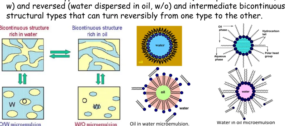
The two basic types of microemulsions are direct (oil dispersed in water, o/
w) and reversed (water dispersed in oil, w/o) and intermediate bicontinuous
structural types that can turn reversibly from one type to the other.
Bandow et al., 1987; Ayyup et al., 1988; Hou and Shah, 1988; Lal et al., 1998; Zhang et al., 2002). This review aims to give a vivid look on the use of microemulsions for synthesizing and controlling the grain size and morphology of the nanoparticles and at the same time will summarize the most recent work car-ried out in the synthesis of organic and inorganic nanoparticles by this method.
2. Microemulsions: past and current state
The word microemulsion was originally proposed bySchulman
et al. (1959). They prepared a quaternary solution of water, benzene, hexanol, andk-oleate which was stable, homoge-nous and slightly opalescent. These systems became clear as soon as a short chain alcohol was added. In the years between 1943 and 1965 Schulman and co-workers described how to prepare these transparent systems. Basically a coarse (or macro) emulsion was prepared and the system was then titrated to clarify by adding a co-surfactant (second surface ac-tive substance). When the combination of the four components was right, the system cleared spontaneously. Most of the work reported by Schulman dealt with four component systems. Hydrocarbons (aliphatic or aromatic), ionic surfactants, co-surfactants (generally 4–8 carbon chain aliphatic alcohol) and an aqueous phase. Schulman had previously published extensively in the field of monolayers and applied what he had learnt in that field to explain the formation of microemul-sions. He proposed that the surfactant and co-surfactant, when properly selected, form a mixed film at the oil/water interface, resulting in an interfacial pressure exceeding the initial positive interfacial tension. To summarize, the basic observation made by Schulman and co-workers was that when a co-surfactant is titrated into a coarse microemulsion composed of a mixture of water/surfactant in a sufficient quantity to obtain microdro-plet, the result may be a system which is low in viscosity, trans-parent, isotropic, and very stable. The titration from opaque emulsion to transparent solution is spontaneous and well de-fined. It was found that these systems are made of spherical mi-cro droplets with a diameter between 600 and 8000 nm. It was only in 1959 that Schulman proposed to call these systems microemulsions. Previously he used terms such as transparent water and oil dispersion, oleophatic hydromicelles or hydro-pathic oleomicelles. Since this time, microemulsions have found a wide range of applications, from oil recovery to syn-thesis of nanoparticles, as reported byChhabra et al. (1997). Microemulsions are isotropic, macroscopically homogeneous, and thermodynamically stable solutions containing at least three components, namely a polar phase (usually water), a nonpolar phase (usually oil) and a surfactant. On a micro-scopic level the surfactant molecules form an interfacial film separating the polar and the non-polar domains. This interfa-cial layer forms different microstructures ranging from droplets of oil dispersed in a continuous water phase (O/W-microemulsion) over a bicontinuous ‘‘sponge’’ phase to water droplets dispersed in a continuous oil phase (W/O-microemulsion). The latter can be used as nanoreactors for the synthesis of nanoparticles with a low polydispersity (Julian
et al., 2006; Destree et al., 2008; Zhong-min et al., 2007; Wanz-hong et al., 2006). Different types of microemulsions are known, such as water-in-oil (W/O), oil-in-water (O/W) and water-in-sc-CO2(w/sc-CO2).
3. Reverse micelles as nanoreactor
Surfactant molecules are dissolved in organic solvents to form spheroidal aggregates that are called as reverse micelles (Pileni,
1989). Here the polar head groups point inwards towards the core. Reverse micelles can be formed in the presence or ab-sence of water. If the medium is free of water then aggregates are very small, while the presence of water makes large surfac-tant aggregates. Water is readily solubilized in the polar core and form ‘‘water pool’’ contents. These water pool contents are characterized byWi.e. water-surfactant molar ratio. The aggregates containing a small amount of water (W!< 15) are usually called reverse micelles whereas aggregates corre-sponding to droplets containing a large amount of water mol-ecules (W!> 15) are called microemulsions (Luisi et al., 1986). Depending on the proportion of various components and the hydrophilic-lipophilic balance value of the surfactant used, the formation of microdroplets can be in the form of oil-swol-len micelles dispersed in water as oil-in-water (O/W) micro-emulsion or water swollen micelles dispersed in oil as for water–in-oil (W/O) microemulsion, also called reverse micro-emulsion (Fig. 1). These nanodroplets can be used as nanore-actors to carry out the chemical reactions (Fig. 1). It was initially assumed that these nanodroplets could be used as tem-plates to control the final size of the particles, however, the re-search carried out in the last few years has shown that besides the droplet size, several other parameters also play an impor-tant role in the final size distribution.
In short, reverse micelles can be defined as ‘‘Water in oil microemulsion in which polar head groups of surfactant mol-ecules are attracted by aqueous core and directed towards in-side and hydrocarbon chain i.e. a polar part is attracted by non aqueous phase and directed towards outside’’. It consists of nanometer sized, monodispersed water droplets. It can eas-ily control the size and shape of the aqueous core by varying the value ofW!. The reverse-micelles obtained at a particular ratio of the aqueous phase to the surfactant leads to uniform-size nanoreactors and have an aqueous core of 5–10 nm (Luisi
et al., 1986) in which it is possible to precipitate the inorganic and organic material.
Apart from the use of reverse micelles in synthetic chemis-try, it can also be used in synthesis of biologically important systems, e.g. reactions based on enzymes are basically performed in aqueous solution. The conversion of non-polar
Oil phase Aqueous phase Hydrocarbon tail Polar head group
Figure 1 A typical structure of reverse micelle.
Microemulsion method: A novel route to synthesize organic and inorganic nanomaterials 399
to branched tubes, and a minimal surface type of structure similar to that established for bicontinuous cubic phase) but picture them as being thermally disrupted or melted. Talmon and Prager were the first to provide a thermodynamic model for bicontinuous microemulsion (Fig. 6b).
7. Supercritical CO2microemulsions
Much attention has been paid to the synthesis of nanoparticles in water-in-supercritical CO2microemulsions (Ohde et al.,
2001, 2002a,b,c). Using conventional water-in-oil microemul-sions for nanoparticle synthesis, the main problem which arises is the separation and removal of solvent from products. Super-critical carbon dioxide used as a solvent offers several advan-tages such as fast reaction speed, rapid separation and easy removal of solvent from nanoparticles. This method has been used to produce Ag and Cu (Ohde et al., 2001) and CdS and ZnS (Ohde et al., 2002) nanoparticles. Hydrogenation of olefins catalysed by Pd nanoparticles in a water-in-CO2
micro-emulsion has also been reported byOhde et al. (2002a,b,c). The selectivity coefficients for the counterion exchange in the water-AOT-heptane microemulsion interface were determined by using pseudo-phase ion exchange formalism (Goncalves et al., 2003). Theoretical results have been success-fully compared to quenching of the RuL4!
3 luminescence
emis-sion measurements. Finally, the catalytic activity of metallic particles synthesized in AOT microemulsions has been a field
of high activity. Using water/AOT/supercritical CO2
micro-emulsions,Ohde et al. (2002a,b,c)showed that hydrogen gas can cause reduction of a number of metal ions including Pd2+dissolved in the water core of the microemulsion. After
reduction, the hydrogen gas can also serve as a starting material for in situ hydrogenation in supercritical CO2. The
hydrogena-tion of 4-methoxycinnamic acid to 4 methoxyhydrocinnamic acid, hydrogenation of trans-stilbene to 1,2-diphenylethane and hydrogenation of maleic acid to succinic acid were performed in supercritical CO2microemulsions catalysed by
Pd nanoparticles (size range of about 5–10 nm). Further studies (Ohde et al., 2002a,b,c) have shown that rhodium nanoparticles dispersed in CO2microemulsions are also effective catalysts for
rapid hydrogenation of arenes in supercritical CO2.
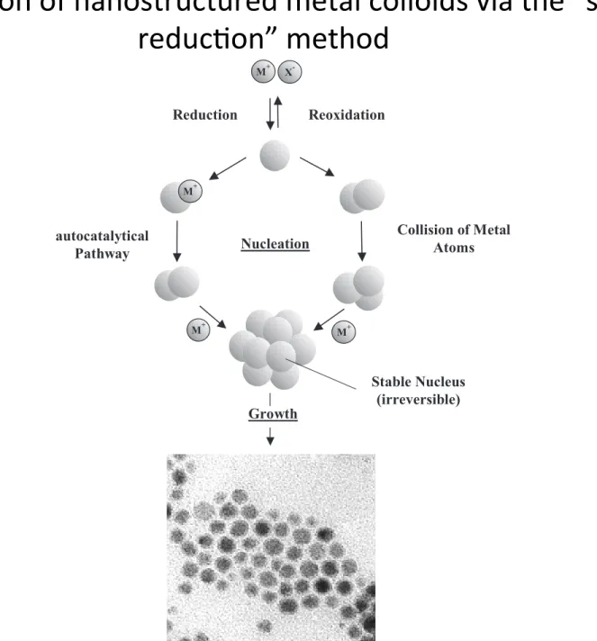
8. Mechanism and dynamic of nanoparticle synthesis
The aqueous droplets continuously collide, coalesce, and break apart, resulting in a continuous exchange of solution content. In fact, the half-life of the exchange reaction between the drop-lets is of the order of 10!3–10!2s (Atik and Thomas, 1981a).
Two models have been proposed to explain the variation of the size of the particles with the precursor concentration and with the size of the aqueous droplets. The first is based on the LaMer diagram (La Mer and Dinegam, 1950), which has been proposed to explain the precipitation in an aqueous med-ium and thus is not specific to the micro emulsion. This dia-gram (Fig. 7) illustrates the variation of the concentration with time during a precipitation reaction and is based on the principle that the nucleation is the limiting step in the precip-itation reaction. In the first step the concentration increases continuously with increasing time. As the concentration reaches the critical supersaturation value, nucleation occurs. This leads to a decrease of the concentration. Between the con-centrationsC"
maxandC"minthe nucleation occurs. Later the
de-crease of the concentration is due to the growth of the particles by diffusion. This growth occurs until the concentration reaches the solubility value. This model has been applied to the micro emulsion medium, i.e., that nucleation occurs in the first part of the reaction and later only growth of the par-ticles occurs. If this model is followed, the size of the parpar-ticles will increase continuously with the concentration of the precursor or a minimum in the variation of the size with the concentration can also be expected. This stems from the fact that the number of nuclei is constant and the increase of
water
oil
Figure 5 Oil in water microemulsion.
(a) (b)
Figure 6 Bicontinuous structure.
I
I II II
Nucleation Growth Solubility Time C o n ce n tr at io n Cs C* min C* max
Figure 7 LaMer diagram.
Microemulsion method: A novel route to synthesize organic and inorganic nanomaterials 403
Oil in water microemulsion.
Water in oil microemulsion
substrates is impossible. The use of reverse micelles allows one to convert either water or oil – soluble substrates into prod-ucts. During the water pool exchange, non-polar compounds are in contact with the enzyme favoring the catalytic reaction (Fletcher et al., 1986).
4. Water-in-oil (W/O) micro emulsions
A ‘‘water-in-oil’’ micro emulsion is formed when water is dis-persed in a hydrocarbon based continuous phase, and is nor-mally located towards the oil apex of a water/oil/surfactant triangular phase diagram. In this region, thermodynamically driven surfactant self-assembly generates aggregates known as reverse or inverted micelles (Ekwall et al., 1970); spherical reverse micelles, which minimize surface energy, are the most common form. Added polar or ionic components will become compartmentalized into the central cores of these reversed mi-celles, hence affording fine dispersion of inorganic and organic materials in oil (Fig. 2). It is important to recognize that these systems are dynamic i.e. micelles frequently collide via random Brownian motion and coalesce to form dimers, which may ex-change contents then break apart again. Clearly, any inorganic reagents encapsulated inside the micelles will become mixed. This exchange process is fundamental to nanoparticle synthesis inside reversed micellar ‘templates’, allowing different reac-tants solubilized in separate micellar solutions to react upon mixing. Micelles in these systems can be described as ‘‘nanore-actors’’, providing a suitable environment for controlled nucle-ation and growth. In addition, at the latter stages of growth, steric stabilization provided by the surfactant layer prevents the nanoparticles from aggregating (Lopez-Quintela et al.,
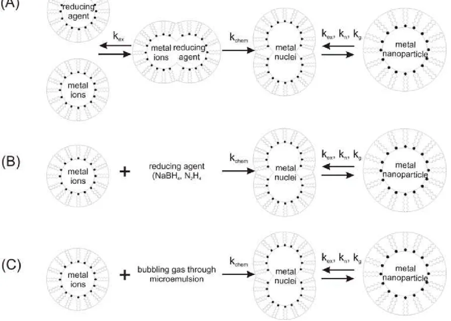
2004). In general there are two methods for nanoparticle syn-thesis using microemulsion techniques (Osseo-Asare and
Arriagada, 1990). The first method is called the one micro-emulsion method. This method includes ‘‘energy triggering’’ and the ‘‘one micro emulsion plus reactant’’ method. In the en-ergy triggering method, the reaction is initiated by implement-ing a triggerimplement-ing agent into the simplement-ingle micro emulsion which contains a reactant precursor (Fig. 3a). This fluid system is activated in order to initiate the reactions that eventually lead to particle formation. For example, pulse radiolysis and laser
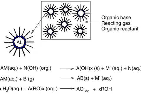
photolysis have been used to trigger the preparation of nano-size gold particles (Kurihara et al., 1983). However in one microemulsion plus reactant method, the reaction is initiated by directly adding the pure reactant (liquid or gaseous phase) into the micro emulsion containing another reactant (Fig. 3b). The ions e.g. metals are first dissolved in the aqueous phase of a W/O microemulsion. Then the precipitating agent, in the form of an aqueous solution e.g. salt NaOH or a gas phase e.g. NH3(g), CaCO3(g), is fed into the micro emulsion
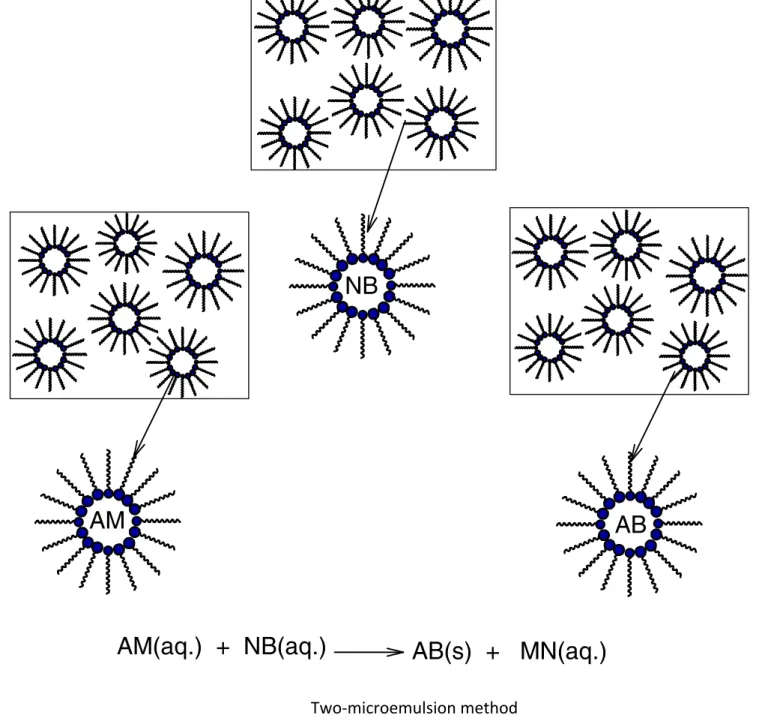
solu-tion. Another scenario within the one micro emulsion-plus reactant method is that the precipitating agent is first dissolved in the polar core and a metal-containing solution (e.g. organic precursor) is subsequently added into the micro emulsions. The one-micro emulsion method generally is driven by the fusion-based process, since the second trigger/reactant is dif-fusing into the droplets containing the reactant in the used micro emulsion. The second method which is also often used for preparing nanoparticles is the two micro emulsion meth-ods. Two reactants A and B, which are dissolved in the aque-ous nanodroplets of two separate micro emulsions are mixed as shown in (Fig. 4). This method relies on fusion-fission events between the nanodroplets.
In order to produce the nanoparticles, two micro emulsions carrying the appropriate reactants are mixed. The Brownian motion of the micelles leads to intermicellar collisions and suf-ficiently energetic collisions lead to a mixing of micellar con-tents. The chemical reaction starts when there are fusion-fission event between the droplets as a perquisite for the mixing of the reactants. After the chemical reaction has taken place at the nanodroplets, critical number of molecules is produced (Ncrit), this results in nuclei formation and furthermore leads
to the growth of nanoparticles.
The micelles undergo numerous collisions and thereby the reactants are exchanged, mixed, and react to form the product. Nanoparticles of different materials have been prepared using this technique. The particles produced by the simple addition method can be much larger than the original droplet size but in the latter method the sizes are much smaller than the origi-nal droplet size (Li and Park, 1999). In the micro emulsions mixing method, the two reactants are pre micellized in two sep-arate micro emulsions and are brought into contact through intermicellar exchange to conduct the reaction. In some cases, where reaction rates are very rapid, the overall reaction rate is governed by the intermicellar exchange rate. Unlike in gas-li-quid systems, here the fusion-fission and exchange of contents between colliding micelles lead to reaction and also disrupt the initially established Poisson distribution of the reactant in the micelles. The intermicellar exchange rate plays a significant role in the nanoparticle formation and the effect has been stud-ied (Bagwe and Khilar, 2000). Different research groups have obtained trends for the effect of intermicellar exchange rate (Bagwe and Khilar, 2000), water-to-surfactant molar ratio (Monnoyer et al., 1995), and concentration of reactants (Monnoyer et al., 1995). Some differences exist in the literature on the effect of these parameters on the terminal particle sizes. For instance, different research groups have reported qualita-tively different findings on the effect of water-to-surfactant molar ratio on the terminal particle size (Monnoyer et al.,
1995; Bagwe and Khilar, 2000). Although the formation pro-cess involves diffusion, collision, exchange, reaction, nucle-ation, and growth of nuclei, timescale analysis of these processes leads to different models. One of the early attempts
water
Figure 2 Water in oil microemulsion.