Coordinated Transmissions to Direct and Relayed
Users in Wireless Cellular Systems
Chan Dai Truyen Thai*, Petar Popovski*, Megumi Kaneko
†
and Elisabeth de Carvalho*
*Department of Electronic Systems, Aalborg University
†
Graduate School of Informatics Yoshida Honmachi, Kyoto University
Email:
{
ttc, petarp, [email protected]
}
, [email protected]
Abstract—The ideas of wireless network coding at the physical layer promise high throughput gains in wireless systems with relays and multi–way traffic flows. This gain can be ascribed to two principles: (1) joint transmission of multiple communication flows and (2) usage of a priori information to cancel the interference. In this paper we use these principles to devise new transmission schemes in wireless cellular systems that feature both users served directly by the base stations (direct users) and users served through relays (relayed users). We present four different schemes forcoordinated transmissionof uplink and downlink traffic in which one direct and one relayed user are served. These schemes are then used as building blocks in multi– user scenarios, where we present several schemes for scheduling pairs of users for coordinated transmissions. The optimal scheme involves exhaustive search of the best user pair in terms of overall rate. We propose several suboptimal scheduling schemes, which perform closely to the optimal scheme. The numerical results show a substantial increase in the system–level rate with respect to the systems with non–coordinated transmissions.
Index Terms—Cooperative communications, relaying, analog network coding, interference cancelation, a priori information.
I. INTRODUCTION
Recently there have been extensive studies on cooperative, relay–based transmission schemes for extending cellular cover-age or increasing diversity. Several basic relaying transmission techniques have been introduced, such as amplify-and-forward (AF) [3], decode-and-forward (DF) [4] and compress-and-forward (CF) [5]. These transmission techniques have been applied in one-, two- or multi-way relaying scenarios.
In particular, two–way relaying scenarios [1], [2], [6] have attracted a lot of attention, since it has been demonstrated that in these scenarios one can apply techniques based on network coding in order to obtain a significant throughput gain. There are two basic principles used in designing throughput–efficient schemes with wireless network coding:
1) Aggregation of communication flows: instead of trans-mitting each flow independently, the principle of net-work coding is used in which flows are sent/processed jointly;
2) Intentional cancellable interference: in analog network coding, flows are allowed to interfere, knowinga priori that the interference can be cancelled by the destination. The motivation for this work was to generalize the two basic principles from above and devise novel transmission schemes in multi-user scenarios. We consider scenarios based
on cellular networks with relays, where direct and relayed users are served in uplink/downlink.
Assume for example that a direct user wants to send a packet to the Base Station (BS), while the BS has a packet to send to a relayed user. In a conventional cellular system, these packets are sent over separate UL/DL phases. Instead, the BS may first send the packet which is received at the Relay Station (RS). While the RS forwards this packet to its intended relayed user, the direct user sends its packet to the BS, thus saving the required transmission time compared to the conventional method. We term such a scheme coordinated direct/relay (CDR) transmission scheme. Transmission schemes that are related to some of the schemes proposed in this paper have appeared before in the literature [8], [9], or to relayed users [7]. However, in this paper we have used the principles described above to generalize the transmission schemes to in total four transmission schemes, which represent a superset of the existing schemes. As in the case of wireless network coding, our schemes take advantage of the combining of uplink and downlink traffic flows. Furthermore, we consider multi–user (>2) scenarios, in which the proposed CDR schemes are used as building blocks for creating novel scheduling schemes. We consider the rate–optimal scheme, which requires exhaustive search across the pairs of users and is complex. Therefore, we propose several suboptimal schemes and the results show that they perform closely to the optimal one, while all the proposed schemes show significant rate gains with respect to the reference system in which the CDR schemes are not employed.
This paper is organized as follows. Section II describes the system model for two-user and multi-user networks. The two-user and multi-user schemes are described and analyzed in Section III and IV, respectively. Section V presents the numerical results and Section VI concludes the paper.
II. SYSTEMMODEL
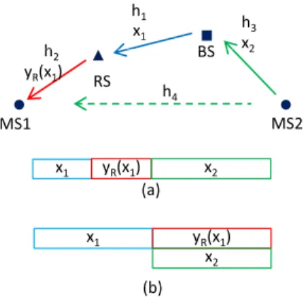
The basic setup for a CDR scheme is the scenario with one base station (BS), one relay (RS), and two users (MS1
and MS2), see Fig. 1. All transmissions have a unit power and normalized bandwidth of 1 Hz. Each of the complex channels hi, i ∈ {1,2,3,4,5}, is reciprocal, known at the
TABLE I WAITINGLIST
Frame 1 2 3
DD 1 4 5
DU 2 3
RD 6 7 9
RU 8 10
a packet or a single symbol, and it will be clear from the context. For example, the packet thatBSwants to send to the
MS1 is denoted by x1; but if we want to express the signal received, then we use expressions of typey=hx1+z, where all variables denote symbols (received, sent, or noise). We introduce further notation: x4 is the packet sent from BS to
MS2, while the packets thatBS needs to receive arex3 from
MS1andx2 fromMS2. Note that the example on Fig. 1 does not show traffic patterns that involve x3 andx4.
The basic time unit is one time slot. A direct transmission takes one slot. One transmission through the relay takes also one slot: in the downlink, the first half of the slot is for the transmission BS-RS, while the second slot is is for the transmission RS-MS. The uplink transmission is similar. Relaying with amplify–and–forward (AF) is used, and therefore the transmission BS-RShas the same duration with the transmission RS-MS(and vice versa in the uplink). The received signal and Additive White Gaussian Noise (AWGN) at BS, RS, MS1 and MS2 in time slot j is denoted by
yij and zij ∼ CN(0, n), i ∈ {B, R,1,2}, j ∈ {1,2}.
The instantaneous Signal-to-Noise Ratio (SNR) for the i−th channel is γi = |hi|2/n and its capacity is denoted as
C(γi) = log2(1 +γi). The direct channelBS-MS1is assumed
weak and MS1 relies only on the amplified/forwarded signal fromRSin order to decode the signal fromBS. At the RS, the received signal is scaled to comply with transmit constraint.
In the scenarios with more than two users, where scheduling also needs to be applied, there are k relayed users and k
direct users. The transmissions are organized in sessions. In a session, each user has a packet for an uplink or downlink with probability ofpuor 1−pu, respectively. An example of
traffic pattern is shown in table I which lists the user numbers in 4 traffic types: direct downlink (DD), direct uplink (DU), relayed downlink (RD) and relayed uplink (RU). Direct users 1, 4, 5 request a downlink, direct users 2, 3 request an uplink, relayed users 6, 7, 9 request a downlink and relayed users 8, 10 request an uplink. One session consists of multipleframes, each frame consists of two slots in which a CDR transmission is performed. We slightly abuse the notation for the wireless channels by not explicitly indexing the channel with the particular user: hi, i∈ {1,2,3,4,5} thus refers to a channel
in the set currently considered for a certain coordination. All channels are assumed known at BSand constant during each frame, but vary independently from frame to frame.
III. SCHEDULING INTWO-USERSCHEMES
We propose four types of two-user schemes, each combining user pairs (DU, RD), (DD, RU), (DD, RD) and (DU, RU) for which there are packets to be transmitted. These schemes are compared with reference ones in terms of sum–rate.
x1
h BS
h3 x2 h1
h2 yR(x1)
BS
RS
MS2 MS1
2
h4
x y (x ) x
x1 yR(x1)
(b)
x1 yR(x1)
(a) x2
x2
(b)
Fig. 1. Reference scheme 1 (a) and coordinated scheme 1 (b).
A. Reference Schemes
In the reference schemes there are only orthogonal transmis-sions and no interference. Four reference schemes correspond-ing to four user pairs described above have the same time slot structure, only the order and direction of transmissions for the relayed user are different. The reference scheme is denoted
Ei,i∈ {1,2,3,4}.
Fig. 1 (a) describes the transmissions in reference scheme 1. In the first half slot, BS transmits x1 and RS receives
yR1 = h1x1+zR1, in the second half-slot, RS scales yR1 with amplification factor gE1 = |h 1
1|2+n so that the transmit power is 1 and transmits √gE1yR1 andMS1 receives y11 =
h2
√
gE1yR1+z11=h2
√
gE1h1x1+h2
√
gE1zR1+z11, in the second slot,BSreceivesyB2=h3x2+zB2.MS1decodesx1 fromy11. SINR for the first user in the reference scheme 1 is therefore
γE11=
gE1|h1h2|2
gE1|h2|2n+n
= γ1γ2
γ1+γ2+ 1
. (1)
BS decodes x2 from yB2. SNR for the second user in the
reference scheme 1 is γE12 = |h3| 2
n =γ3. The scheme thus
has sum–rate ofCE1= 12C(γE11) + C(γE12). All reference
schemes have the same sum–rate formula due to channel reciprocity and symmetry in AF relaying CE1 = CE2 =
CE3=CE4.
B. Proposed Basic Coordinated Schemes
In CDR schemes, the three transmissions are scheduled as one transmission in one slot and two simultaneous transmis-sions in the other slot although the order and direction of the transmissions are different. The transmissions are arranged so that the interference is reduced or canceled. There are four basic coordinated schemes denoted asSi, i∈ {1,2,3,4}.
Coordinated SchemeS1(Fig. 1b),BStransmitsx1 toRSin the first slot, RS receives yR1 = h1x1+zR1. In the second
slot,RSscales the received signal with the amplification factor
gS1=|h1|12+n and transmits it. At the same time,MS2 trans-mits x2. MS1 therefore receives signal y12 =h2
√
gS1yR1+
h4x2 + z12 = h2
√
gS1h1x1 +h2
√
gS1zR1 +h4x2 +z12 and BS receives yB2 = h1
√
gS1yR1 + h3x2 + zB2 =
h1
√
gS1h1x1+h1
√
h1
yR (x3, x4) h3
h1
x h3
h1
yR(x2x3) h3
x3
h2 BS
RS
MS2 MS1
3 x4
x3 yR(x3 x4) h5
h4
x1 h2
yR (x1) BS
RS
MS2 MS1
3
x4
x y (x )
h5 x3
h2
yR (x2 ,x3) BS
RS
MS2 MS1
3 x2
x y (x )
h5
x3 x4
yR(x3, x4) x1
x4
yR(x1) x3
x2
yR(x3)
(S2) (S3) (S4)
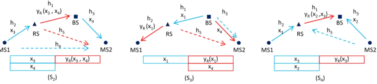
Fig. 2. Basic coordinated schemes S2, S3 and S4.
and the channels, it cancels the component inx1inyB2, gets ˜
yB2=h3x2+h1
√
gS1zR1+zB2 and decodesx2 with SNR
γS12=
|h3|2
|h1|2gS1n+n = |h3|
2(|h
1|2+n) 2|h1|2n+n2
= γ3(γ1+ 1) 2γ1+ 1
.
(2)
MS1 decodesx1 treatingx2 as interference with SINR
γS11=
|h2|2gS1|h1|2
|h2|2gS1+|h4|2+n
= γ1γ2
γ1+γ2+γ4+γ1γ4+ 1
.
(3) The sum–rate is thereforeCS1= C(γS11) + C(γS12).
Coordinated Scheme S2 (Fig. 2): MS1transmitsx3 andBS transmitsx4simultaneously in the first slot.RSreceivesyR1=
h2x3+h1x4+zR1 andMS2 receives y21 =h4x3+h3x4+
z21. In the second slot,RSscales the received signal with the amplification factor gS2= |h1|2+|1h2|2+n and transmits it. BS receives yB2 =h1
√
gS2yR1+zB2 and MS2 receives y22 =
h5
√
gS2yR1+z22. Since BS knows x4 and the channels, it cancels x3 component in yB, gets y˜B2 = h1
√
gS2(h2x3+
zR1) +zB2 and decodes x3. At MS2, y21 and y22 form a virtual 2-antenna received signal y = Hx+z, with y = [y21 y22]T,x= [x4 x3]T,z= [z21 h5
√
gS2zR1+z22]T, and
H=
h3 h4
√
gS2h1h5
√
gS2h2h5
. (4)
We can apply MMSE receiver using (13) in the Appendix to have the sum–rate
CS2= C
γ
1γ2 2γ1+γ2+ 1
+CS22 (5)
in which CS22= C
hγ
3(γ1+γ2+γ5+1)+γ5(γ1+γb2) (γ4+1)(γ1+γ2+γ5+1)+γ2γ5
i
.
Coordinated SchemeS3(Fig. 2):BStransmitsx1in the first slot, RSrelays it toMS1andBStransmitsx4 simultaneously in the second slot. The transmissions are yR1 = h1x1 +
zR1, gS3 = |h1|12+n, y12 = h2
√
gS3yR1 + z12, y21 =
h3x1+z21, y22 =h5
√
gS3yR1+h3x4+z22. MS1 decodes
x1 from y12 without interference. At MS2, y21 and y22 form a virtual 2-antenna received signal y =Hx+z, with
y= [y21 y22]T,x= [x4 x1]T,z= [z21 h5
√
gS3zR1+z22]T, andH=
0 h3
h3
√
gS3h1h5
. We can apply MMSE receiver
using (13) in the Appendix to have the sum–rate
CS3=CS31+CS32= C
γ
1γ2
γ1+γ2+ 1
+CS32 (6)
withCS32= C
h γ
3(γ3+1)(γ1+1) (γ1+γ5+1)(γ3+1)+γ1γ5
i
.
Coordinated SchemeS4(Fig. 2):MS1transmitsx3andMS2 transmits x2 in the first slot, RS transmits what it received in the second slot. The transmissions are yR1 = h2x3 +
h5x4+zR1, gS4=|h 1
2|2+|h5|2+n, yB1=h3x2+zB1, yB2=
h1
√
gS4yR1+zB2.BSdecodesx2andx3fromyB1andyB2.
Similar to the previous schemes, we havey=Hx+z, with
y= [yB1yB2]T,x= [x2x3]T,z= [zB1h1
√
gS4zR1+zB2]T, andH=
0 h3
√
gS4h1h2
√
gS4h1h5
. We can apply MMSE
receiver using (13) in the Appendix for both users to have the sum–rate we have CS4=CS41+CS42, in which
CS41= C
γ1γ2(γ3+ 1)
γ1γ5+ (γ1+γ2+γ5+ 1)(γ3+ 1)
, (7)
and
CS42= C
γ3+
γ1γ5
γ1+γ2+γ5+γ1γ2+ 1
. (8)
C. Coordinated Schemes with User Priority
In the reference schemes, information for the relayed and direct user is transmitted separately. On average, the BS-relayed user rate is lower than the BS-direct user rate because of AF relaying. However, in some of the coordinated schemes, the BS-relayed user rate may be higher than or approximately equal to the BS-direct user rate. In addition, with the same amount of resource (transmit power, time slots...) a coordi-nated scheme can increase the sum-rate by allocating more resource to the direct user than the amount which is used in basic coordinated schemes. In this section, we introduce a prioritizing factor denoted as λ,−1 ≤ λ ≤ 1. If λ > 0, the direct user has more priority than in the basic coordinated scheme and the relayed user has less priority and vice versa. Whenλ >0, the scheme begins with two time slots as in a basic coordinated scheme however the length of each time slot is 1−λ symbol time instead of 1 symbol (as TSi1 and
TSi1in Fig. 3). The residual time with a length of2λis used for an additional transmission between BS and the direct user (TSi3). Whenλ <0, the additional transmissions are from BS
to RS and RS to the relayed user for a relayed downlink or in opposite order for a relayed uplink. Ifλ= 1 or λ=−1, the whole time is used for the direct user or the relayed user respectively, which is not considered.
The average rate for coordinated schemeiwith prioritizing factorλis
CSi0 =
(1−λ)(CSi1+CSi2) + 2λC(γ3) for λ >0
(1 +λ)(CSi1+CSi2)−λC(γR) for λ <0
Reference frame DD RD DU RU
RDa1 RDb1 DD
d d f Si(λ) Sj(λ)
TSi1 TSi2
Basic coordinated scheme (λSi= 0)
Coordinated frame Si,j Si(λSi) Sj(λSj)
λSi
TSi1 TSi2 TSi3
TSi1 TSi2 TSi3b
2λSi
Coordinated scheme with prioritized direct user (λi> 0)
‐λSi
Coordinated scheme with
prioritized relayed user (λi< 0) TSi3
‐λSi
1+λSi 1+λSi
TSi1 TSi2 TSi3b
p y (i ) TSi3a
Fig. 3. Frame format for reference, basic and prioritizing coordinated schemes. a or b refers to either of the BS-RS or RS-relayed user transmission.
withγR=γ γ1γ2 1+γ2+1.
IV. SCHEDULING INMULTI-USERSCHEMES
This part presents different ways of scheduling transmis-sions in a session. At the beginning of a session, BSreceives requests for uplink/downlink and channel information from some users. It schedules appropriate transmissions in the first frame according to one of the schemes below. After that, it receives channel information and schedules for the new frame and so on until all requests in the session are fulfilled.
Note that one frame has two coordinated schemes, such that we use the notationSi, jto denote the fact that the frame contains the coordinated schemes SiandSj.
A. Multi-user Reference Scheme
A frame in the multi-user reference scheme contains 4 time slots for 4 traffic types (DD, RD, DU, RU). The users of each traffic type are served according to first-in-first-out discipline. If there is not a packet corresponding to a slot, it is left empty. A slot for a relayed user is divided into two small slots: one for the transmission between BS and RS and one for the transmission between RSand the relayed user. In the example of table I, the first, second and third frames are (1, 2, 6, 8), (4, 3, 7, 10) and (5,∅, 9,∅) respectively. In slot∅ there is no transmission.
B. Coordinated Schemes
Instead of transmitting packets of 4 traffic types separately in a frame, we can use the coordinated schemes described in part III-B to combine the transmissions. In order to always have 4 traffic types (DD, RD, DU, RU) in a frame, only two types of combining are possible. Those are S1,2, which includes S1 (DU, RD) and S2 (DD, RU), and S3,4, which includes S3 (DD, RD) and S4 (DU, RU). The packets are thus transmitted frame by frame according to first-in-first-out discipline using one of these two combining types. If S3,4is used in the example in table I, the frames are [(1, 6), (2, 8)], [(4, 7), (3, 10)], [(5, 9), ∅]. In a frame, the transmissions of
S3 or S4 be can performed first; and after that are those of the other.
-1 -0.5 0 0.5 1
0 1 2 3 4 5 6 7 8
Rate (b/s/Hz)
C S11 C
S21 C
S31 C
S41 C
S12 CS22 CS32 CS42 CE1 CE2
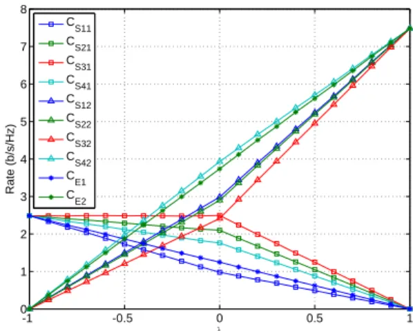
Fig. 4. Average rates for different prioritizing factor values
C. Proposed Multi-user Schemes
As users experience different channel qualities within each frame, the achieved performance will highly depend on the chosen user combinations, in each scheme. With an exhaustive search among the users and sum–rate estimating for each case and both combining types S1,2 and S3,4, we can find a combination of four users and a combining type which has the highest sum–rate in the current frame.
The complexity for CDR with exhaustive search, however, is prohibitively high since we have to calculate the sum–rate for every permutation of the packets. It is necessary to propose some sub-optimal schemes which requires a lower complexity without a significant rate loss. Such a reduction of the search space would be, for example, if only combination ofS3 and
S4in a frame is considered (thus, the S3,4combining type), without considering the possibility to use the schemesS1and
S2.
Another suboptimal scheme is Best Direct User CDR (BD-CDR): first, the direct downlink user which has the best channel toBS(max(γ3)) is picked. The downlink relayed user which has the best combination with that direct user is chosen after that. Then we have a sub-optimal coordinated scheme of S3. We can do similarly for S1, S2, S4 and choose the higher of S12 and S34. In Best Relayed User CDR scheme (BRCDR), the relayed downlink user which has the best relayed channel to BS (max( γ1γ2
γ1+γ2+1)) picked first. The steps after that are processed in a similar way to BDCDR.
V. NUMERICALRESULTS
Computer simulations with network scenarios and parame-ters as presented in part II is conducted to illustrate the sum– rate for the reference and proposed schemes.
In case of two users, Fig. 4 shows the rate for the relayed user (Ci1,i∈ {E, S1, S2, S3, S4}), and the direct user (Ci2)
changing as a function of prioritizing factor in reference and coordinated schemes. The case when λ= 0is correspondent to the basic reference and coordinated schemes. When λ
0 5 10 15 20 0.5
1 1.5 2 2.5 3 3.5 4 4.5 5
Average SNR (dB)
Sum-rate (b/s/Hz)
Ref S1,2 CDR S3,4 CDR CDR w/ ES BDCDR
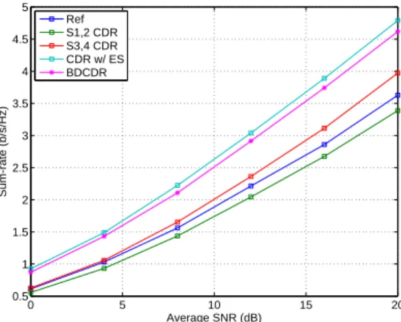
Fig. 5. Average rates for different ordering schemes
in terms of sum–rate because of AF relaying communication between the relayed user and BS. CS42 is the highest among
Ci2 because as seen in (8), always higher thanCE2= C(γ3), thatBSexploits the information in the second time slot beside the information it receives in the first time slot which is equal toC(γ3).CS32, always lower thanC(γ3), is the lowest among Ci2 because MS2 only receives information in time slot 2 which is interfered by the transmission of RS. On contrary,
CS31is the highest amongCi1sinceMS1receives information fromRSwithout any interference in a full time slot compared to half slot in reference scheme. Because γS31 =γR, when λ <0,CS31 does not change therefore decreasing a negative
λ does not bring any benefit but a decrease in the sum–rate.
CS11 is the lowest due to the interference from MS2 atMS1 over the inter-user channel.
In multi-user case with k= 10, Fig. 5 compares the sum– rate for different CDR schemes withpu= 12, λ= 0. The CDR
scheme with exhaustive search has the highest sum–rate due to the optimal combination of transmissions in each frame. The BDCDR scheme with much lower complexity achieves a slightly lower sum–rate since the rate for all scheme increases with γ3 which is optimal in a Best Direct scheme and the channels are independently distributed. CDR with only S3,4 has much lower sum–rate since there is no choice among the users. The S1,2 CDR even has a lower sum–rate than the reference scheme due to useless inter-user interference in S1.
VI. CONCLUSION
In this paper, we have proposed coordinated schemes for a network with a direct user, a relayed user, a base sta-tion and a relay stasta-tion. These schemes are inspired by the principles used in physical–layer network coding: uplink and downlink flows are aggregated, while the interference is not avoided by orthogonalization, but rather through the usage of information that is known a priori. The proposed schemes are shown to have higher sum–rate than the conventional schemes. These schemes are then used as building blocks in multi–user scenarios, where we present several schemes for scheduling pairs of users for coordinated transmissions. In order to avoid scheduling complexity, we propose several suboptimal scheme, which perform closely to the optimal
scheme. We have also discussed the trade-off between the network sum–rate and user prioritization. As a future work, we intend to analyze the proposed schemes in frameworks with proportional fair scheduling and propose related schemes in multi–channel systems, such as OFDMA.
APPENDIX
Consider a 2x2 MIMO system with transmit vector x = [x1 x2]T, receive vector y and channel matrix H. We have transmission vector equationy=Hx+z=h1x1+h2x2+z. Denote
H= h1 h2
=
h11 h21
h12 h22
, (10)
Γ=
γ11 γ21
γ12 γ22
= 1
n
|h11|2 |h21|2
|h12|2 |h22|2
, (11)
γa =
|h∗11h21+h∗12h22|2
n2 , γb=
|h11h22−h21h12|2
n2 ,
N= E[zzH] =n
1 0 0 α
. (12)
By noise whitening [10], we have SINR matrix SINR =
h1HK−z1h1 in which SINR for the first signal stream is
SIN R1=
αγ11+γ12+γb αγ21+γ22+α
(13)
In case the noise power matrix is in another formE[zzH] = n
α 0 0 1
,we have
SIN R1=
γ11+αγ12+γb γ21+αγ22+α
. (14)
ACKNOWLEDGMENT
This work is supported by the Danish Research Council for Technology and Production, grant nr.09−065035.
REFERENCES
[1] P. Popovski and H. Yomo, “Bi-directional Amplification of Throughput in a Wireless Multi–Hop Network,” IEEE VTC, Spring 2006.
[2] S. Katti, S. Gollakota, and D. Katabi “Embracing Wireless Interference: Analog Network Coding,” ACM SIGCOMM, 2007.
[3] G. Farhadi and N. C. Beaulieu, “Capacity of amplify-and-forward multi-hop relaying systems under adaptive transmission,” IEEE Trans. on Comm., vol 58, iss. 3, pp 758-763, 2010.
[4] Y. Zhu, P.-Y. Kam, and Y. Xin, “Differential modulation for decode-and-forward multiple relay systems,” IEEE Trans. on Comm., vol 58, iss. 1, pp. 189-199, 2010.
[5] Z. Liu, M. Uppal, V. Stankovic, and Z. Xiong, “Compress-Forward Coding With BPSK Modulation for the Half-Duplex Gaussian Relay Channel,” IEEE Trans. on Signal Processing, vol. 57, iss. 11, pp. 4467 -4481, 2009.
[6] H. Ning, C. Ling, and K. K. Leung, “Wireless Network Coding with Imperfect Overhearing,” arXiv:1003.4270v1 [cs.IT] 22 Mar 2010. [7] W. Chen, K. B. Letaief, and Z. Cao, “Network Interference Cancellation,”
IEEE Trans. on Wireless Communications, vol. 8, iss. 12, pp. 5982 - 5999, Dec 2009.
[8] B. Bandemer, Q. Li, X. E. Lin, and A. Paulraj, “Overhearing-based Interference Cancellation for Relay Networks,” IEEE VTC, Fall 2009. [9] H. Yomo and E. de Carvalho, “Spectral Efficiency Enhancement with
Interference Cancellation for Wireless Relay Network,” IEEE PIMRC, Fall 2009.