Data Sheet
Cisco 1-Port Channelized STM-1/OC-3 Shared Port
Adapter Version 2
Today's successful businesses require more bandwidth and feature-rich services to
maintain a competitive advantage. To serve these business customers better, service
providers need scalable solutions that not only increase service agility and flexibility,
but also reduce overall network complexity, the time required to provision new
services, and the total cost of ownership. The Cisco
®1-Port Channelized STM-1/OC-3
Shared Port Adapters (SPAs) Version 2 addresses these needs by sharply reducing
the amount of aggregation equipment and interconnectivity needed between edge and
backbone routers. The Cisco 1-Port Channelized STM-1/OC-3 SPA provides Cisco
7600 and Cisco ASR 1000 and ASR 9000 Series Aggregation Services Routers with
support for T1/E1 aggregation. Designed for telcos and Internet service providers
(ISPs), the SPA includes one OC-3/STM-1 port, which can be configured with multiple
channels of n x T1, T1, fractional T1, or DS-0 in a SONET environment or n x E1, E1,
fractional E1, or 64 kbps in an SDH environment.
The Cisco I
nterface Flexibility
(I-Flex) approach combines SPAs and SPA interface processors (SIPs), providing an
extensible design that enables service prioritization for data, voice, and video services. Enterprise and service
provider customers can take advantage of improved slot economics resulting from modular port adapters that are
interchangeable across Cisco routing platforms. The Cisco I-Flex design maximizes connectivity options and offers
superior service intelligence through programmable interface processors that deliver line-rate performance. Cisco
I-Flex enhances speed-to-service revenue and provides a rich set of quality-of-service (QoS) features for premium
service delivery while effectively reducing the overall cost of ownership. This data sheet contains the specifications
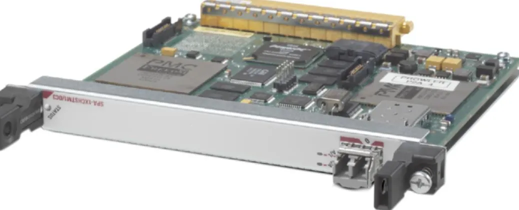
for the Cisco 1-Port Channelized STM-1/OC-3 SPA Version 2 as shown in Figure 1.
Product Overview
When the Cisco 1-Port Channelized STM-1/OC-3 SPA Version 2 is configured in SDH framing mode, it supports
channelization into 63 independent E1 channels (VC-12 mapping). When configured for SONET framing mode, the
SPA supports channelization into 84 independent T1 channels (VT1.5 mapping or CT-3 mapping into STS-1).
Multilink Point-to-Point Protocol (MLPPP) is supported in hardware to enable link aggregation greater than T1. Up
to 12 individual T1s can be combined within a multilink bundle that appears to be a single IP link. This feature
allows service providers to provision greater-than-T1 bandwidth on an incremental basis, without requiring
migration of the circuit and customer-premises-equipment (CPE) infrastructure to T3 facilities. A maximum of 42
multilink bundles can be configured on each SPA, with at least two T1 links in each bundle.
The Cisco 1-Port Channelized STM-1/OC-3 SPA Version 2 is hot-swappable and supports service-transparent
online insertion and removal (OIR), allowing removal of the SPA without affecting the carrier card and other SPAs.
Applications
The 1-Port STM-1/OC-3 SPA Version 2 enables customers to scale services by upgrading bandwidth from
DS-0/E1 to T3/E3 connections - all without any additional interfaces in their routers.
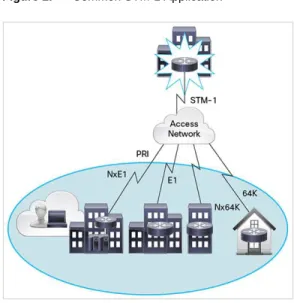
Service providers can use deployed SDH to provision both voice and data circuits all the way to the customer
premises. The Cisco 1-Port Channelized STM-1/OC-3 SPA Version 2 takes advantage of existing SDH
infrastructure, significantly lowering provisioning costs in terms of transmission and routing equipment.
Service providers can connect multiple T1/E1 leased-line customers into one SPA, greatly reducing the amount of
aggregation equipment and interconnectivity needed between edge and remote routers. The SPA also facilitates
support of single-router (edge and backbone) point-of-presence (POP) architectures.
By supporting both Point-to-Point Protocol (PPP) and Frame Relay, the Cisco 1-Port Channelized STM-1/OC-3
SPA Version 2 allows easy transition of connectivity from Frame Relay networks to direct IP leased-line grooming
over SDH networks, thus simplifying the transition to high-bandwidth, full-feature aggregation solutions on Cisco
7600, ASR 1000, and ASR 9000 Series Routers.
Figure 2 shows a common STM-1 application.
Key Features and Benefits
The Cisco 1-Port Channelized STM-1/OC-3 SPA Version 2 offers many advantages, including:
●
Support for Channelized OC-3 to T1, Channelized STM-1 to E1, clear channel T3/E3, subrate T3/E3,
full-rate T1, clear channel E1, Channelized T1/E1, and fractional T1/E1
●
Up to 84 T1 (or 3 T3) ports, 63 E1 (or 3 E3) ports, or 1024 n x DS-0 channels
●
Support for all major encapsulations including MLPPP and Multilink Frame Relay (MLFR)
●
Support for link fragmentation and interleaving (LFI) over Frame Relay (FRF.12) and MLPPP
●
Support for both 1 + 1 SONET Automatic Protection Switching (APS) and SDH Linear Multiplexer Section
Protection (MSP) protocols
Product Specifications
Table 1 lists the product specifications for the Cisco 1-Port Channelized STM-1/OC-3 SPA Version 2, and Table 2
lists the optical parameters.
Table 1. Product Specifications
Features Descriptions
Product compatibility ● Cisco 7600 Series Routers
● Cisco ASR 1000 Series Routers ● Cisco ASR 9000 Series Routers
Minimum software version ● Cisco 7600 Series Routers: Cisco IOS®
Software Release 15.4(2)S and Cisco IOS XE Software Release 3.12.0.0S
● Cisco ASR 1000 Series Routers with Cisco IOS XE Software Releases 3.12.0, 3.11.2, and 3.10.3 ● Cisco ASR 9000 Series Routers with Cisco IOS XR Software Release 5.2.0
Protocols Serial encapsulations:
● High-Level Data Link Control (HDLC) ● Point-to-Point Protocol (PPP), RFC 1662 ● Frame Relay, RFC 1490
Multilink support (bundle limit dependent on number of links per bundle; maximum of 12 links per bundle): ● Multilink PPP (MLPPP), RFC 1990
● Link fragmentation and interleaving (LFI) over Frame Relay (FRF.12) and MLPPP Networking protocols:
● IPv4/IPv6
Cards, ports, and slots 1 port
Connectivity OC-3/STM-1 Small Form-Factor Pluggable (SFP) optics module (refer to optical parameters in Table 2)
Features and functions Up to 84 T1 (or 3 T3) or 63 E1 (or 3 E3) ports
Up to 1022 n x DS-0 channels (where n is 1 to 24) with no T3 ports configured Up to 400 n x DS-0 channels (where n is 1 to 24) with one or more T3 ports configured
Support for Channelized OC-3 to T1, Channelized STM-1 to E1, clear channel T3/E3, subrate T3/E3, full-rate T1, clear channel E1, and Channelized T1/E1
SONET multiplexing: ● OC-3 <-> STS-3 <-> STS-1 <-> VTG <-> VT1.5 <-> T1 <-> N x DS-0 ● OC-3 <-> STS-3 <-> STS-1 <-> T3 <-> T1 <-> N x DS-0 ● OC-3 <-> STS-3 <-> STS-1 <-> T3 ● OC-3 <-> STS-3 <-> STS-1 <-> T3 <-> E1 <-> n x DS-0 SDH multiplexing:
● STM-1 <-> AUG <-> AU-4 <-> VC-4 <-> TUG-3 <-> TUG-2 <-> TU-12 <-> VC-12 <-> E1 <-> n x DS-0 ● STM-1 <-> AUG <-> AU-4 <-> VC-4 <-> TUG-3 <-> TU-3 <-> VC-3 <-> T3/E3
● Internal or line-derived (loop) clocking, independently selectable on each T1 or E1 tributary
Features Descriptions
● Local and remote loopback at the T3/T1 level
● Network loopback at the STM-1/OC-3, T3/E3, and T1/E1 levels ● Response to embedded loopback commands
● Insertion of loopback commands into transmitted signal
● Bit error rate testing (BERT) pattern generation and detection per channel ● Programmable pseudorandom pattern up to 32 bits in length
● T3/E3: All 0s, all 1s, 215, 220, 220 QRSS, 223, alternating 0s and 1s, 1-in-8, and 3-in-24 ● T1/E1: All 0s, all 1s, 211, 215, 220, 220 QRSS, 223, alternating 0s and 1s, 1-in-8, and 3-in-24 ● 32-bit error-count and bit-count registers
● Detection of test patterns with bit error rates up to 10-2
● 24-hour history maintained for error statistics and failure counts, at 15-minute intervals ● 16- and 32-bit cyclic redundancy check (CRC); 16-bit default
SONET/SDH-specific features:
● Compliance with G.707, G.783, G.784, G.957, G.958, and GR-253 ● Supported SONET/SDH alarm and signal events:
◦ Signal failure bit error rate (SF-BER) ◦ Signal degrade bit error rate (SD-BER) ◦ Signal label payload construction (C2) ◦ Path trace byte (J1)
● Section
◦ Loss of signal (LoS) ◦ Loss of frame (LoF) ◦ Error counts for B1
Line
● Line alarm indication signal (LAIS) ● Line remote defect indication (LRDI) ● Line remote error indication (LREI) ● Error counts for B2
Path
● Path alarm indication signal (PAIS) ● Path remote defect indication (PRDI) ● Path remote error indication (PREI) ● Error counts for B3
● Loss of pointer (LOP) ● New pointer events (NEWPTR) ● Positive stuffing event (PSE) ● Negative stuffing event (NSE)
● Path unequipped indication signal (PUNEQ) ● Path payload mismatch indication signal (PPLM)
T3-specific features:
● Channelized T3 with 28 DS-1 lines or 21 E1 lines multiplexed into a T3
● Unchannelized T3 supporting subrate and scrambling formats for Digital Link, ADC/Kentrox, Larscom, Adtran, and Verilink data service units (DSUs)
● C-bit or M23/M13 framing ● Maintenance data link (MDL)
● T3 far-end alarm and control (FEAC) channel support ● Alarm monitoring
● Alarm indication signal (AIS) ● Out of frame (OOF)
● Far-end receive failure (FERF) ● Performance data collection:
◦ Framing bit errors (FERR) (F- or M-bit errors) ◦ P-bit error counts (path-parity errors) ◦ C-bit error counts
◦ Far-end block error (FEBE) counts
Features Descriptions ● G.751 framing ● Alarm monitoring ● AIS ● OOF ● FERF
● Performance data collection: ◦ Framing pattern errors
◦ BIP-8 error counts (path-parity errors) ◦ FEBE counts
● T1-specific features:
◦ D4 Super Frame (SF) or Extended Super Frame (ESF) framing ◦ ANSI T1.403 and AT&T TR 54016 Facility Data Link (FDL) support ◦ Alarm monitoring
◦ AIS ◦ OOF
◦ Far-end alarm failure (yellow or distant alarm)
Performance data collection:
● CRC/bit errors ● Framing bit errors ● Line errored seconds ● Far-end errored seconds ● Far-end severely errored seconds ● Far-end unavailable seconds
E1-specific features:
● CRC4 or non-CRC4 framing in conformance with ITU-T G.703 and G.704 ● Alarm monitoring
● AIS ● OOF
● Remote alarm indication (RAI) ● Performance data collection ● CRC/bit errors
● Framing bit errors ● FEBE
Reliability and availability OIR
Field-replaceable SFP optics modules
Support for both 1 + 1 SONET Automatic Protection Switching (APS) and SDH Linear Multiplexer Section Protection (MSP) protocols
Single SPA software reset
MIBs RFC 2558 MIB (SONET/SDH)
RFC 2495 MIB (T1/E1) RFC 2496 MIB (T3/E3)
Network management Simple Network Management Protocol (SNMP)
Physical specifications Weight: 0.75 lb (0.34 kg) Height: 0.8 in. (2.03 cm) Width: 6.75 in. (17.15 cm) Depth: 7.28 in. (18.49 cm)
Regulatory compliance CE marking
Safety: UL/CSA/IEC/EN 60950-1, IEC/EN 60825 Laser Safety, AS/NZS 60950, FDA Code of Federal Regulations Laser Safety
EMC: FCC Part 15 Class A, ICES 003 Class A, AS/NZS 3548 Class A, CISPR 22 Class B (up to 1GHz), EN55022 Class B (up to 1GHz), VCCI Class A, BSMI Class A, EN 300 386 Telecommunications Network Equipment (EMC), EN50082-1/EN61000-6-1 Generic Immunity Standard, EN55022 Information Technology Equipment (Emissions), EN55024 Information Technology Equipment (Immunity), IEC/EN61000-3-2 Power Line Harmonics, IEC/EN61000-3-3 Voltage Fluctuations and Flicker, IEC/EN61000-4-2 Electrostatic Discharge Immunity (8kV contact, 15kV air), IEC/EN61000-4-3 Radiated Immunity (10V/m), IEC/EN61000-4-4 Electrical Fast Transient Immunity (2kV power, 1kV signal), IEC/EN61000-4-5 Surge AC Port (4kV CM, 2kV DM), IEC/EN61000-4-5 Surge Signal Port (1kV), IEC/EN61000-4-5 Surge DC Port (1kV), IEC/EN61000-4-6 Immunity to Conducted Disturbances
Features Descriptions
(10Vrms), IEC/EN61000-4-8 Power Frequency Magnetic Field Immunity (30A/m), IEC/EN61000-4-11 Voltage Dips, Short Interruptions, and Voltage Variations, 1089-CORE NEBS EMC and Safety, GR-63-CORE NEBS Physical Protection, SR-3580 NEBS Criteria Levels (Level 3)
Telecom (OC3): GR-253 Telecom (STM-1): G.783, G.957
Environmental Specifications Operating temperature: 41 to 104°F (5 to 40°C) Storage temperature: -38 to 150°F (-40 to 70°C) Operating humidity: 5 to 85% relative humidity Storage humidity: 5 to 95% relative humidity
Table 2. Optical Parameters OC-3/STM-1
Transceiver Type
Transmit Power Maximum Power to Receiver, dBm Receiver Sensitivity, dBm Attenuation Range, dB Nominal Distance Between Stations Multimode (MM) short reach -20 dBm min. to -14 dBm max. at 1270 to 1380 nm -8 -23 0 to 7 Up to 2 km Single-mode short reach (SR) -15 dBm min. to -8 dBm max. at 1260 to 1360 nm -8 -23 0 to 7 Up to 2 km Single-mode intermediate reach (IR-1) -15 dBm min. to -8 dBm max. at 1261 to 1360 nm -8 -28 0 to 12 Up to 15 km Single-mode long reach (LR-1) -5 dBm min. to 0 dBm max. at 1263 to 1360 nm -10 -34 10 to 28 Up to 40 km Single-mode long reach (LR-2) -5 dBm min. to 0 dBm max. at 1480 to 1580 nm -10 -34 10 to 28 Up to 80 km
Features Not Supported
The Cisco 1-Port Channelized STM-1/OC-3 SPA Version 2 does not support the following features:
●
E3 multiplexing (Channelized E3)
●
MLPPP or MLFR with unequal speed links in a bundle or higher-speed links than a T1 in a bundle
●
Loopbacks at n x DS-0 channel level
●
Unchannelized STM-1/OC-3 Packet over SONET/SDH (PoS)
Ordering Information
To place an order, visit the
Cisco Ordering Home Page
. Table 3 lists ordering information for the Cisco 1-Port
Channelized STM-1/OC-3 SPA Version 2.
Table 3. Ordering Information
Product Name Part Number
1-Port Channelized STM-1/OC-3 to DS-0 Shared Port Adapter Version 2 SPA-1CHSTM1/OC3V2
OC-3/STM-1 SFP, Multimode Fiber, Short Reach SFP-OC3-MM
OC-3/STM-1 SFP, Single-Mode Fiber, Short Reach SFP-OC3-SR
OC-3/STM-1 SFP, Single-Mode Fiber, Intermediate Reach (IR-1) SFP-OC3-IR1
OC-3/STM-1 SFP, Single-Mode Fiber, Long Reach (LR-1) SFP-OC3-LR1