IBM Enterprise Storage Server
Cay-Uwe Kulzer, Philip Norman, Alison Pate, Roland Wolf
International Technical Support Organization
SG24-5465-00
International Technical Support Organization
SG24-5465-00IBM Enterprise Storage Server
First Edition (July 1999)
This edition applies to the IBM 2105 Enterprise Storage Server. See the PUBLICATIONS section of the IBM Programming Announcement for IBM Enterprise Storage Server for more information about product documentation. Comments may be addressed to:
IBM Corporation, International Technical Support Organization Dept. QXXE Building 80-E2
650 Harry Road
San Jose, California 95120-6099
When you send information to IBM, you grant IBM a non-exclusive right to use or distribute the information in any way it believes appropriate without incurring any obligation to you.
Before using this information and the product it supports, be sure to read the general information in Appendix B, “Special Notices” on page 219.
© Copyright IBM Corp. 1999 iii
Contents
Preface . . . xi
The Team That Wrote This Redbook . . . xi
Comments Welcome . . . xii
Chapter 1. Introduction . . . .1
1.1 Positioning of the Enterprise Storage Server . . . .3
1.2 Benefits . . . .5
1.3 Statement of Direction . . . .11
1.3.1 Terminology . . . .12
1.3.2 S/390 . . . .12
1.3.3 UNIX and Windows NT . . . .13
Chapter 2. Hardware . . . .15
2.1 IBM Enterprise Storage Server Overview . . . .16
2.2 ESS Models and Expansion Rack . . . .17
2.2.1 Enterprise Storage Server Models. . . .17
2.2.2 ESS Expansion Rack feature 2100 . . . .17
2.3 ESS Support of IBM 2105-B09/100 . . . .18
2.3.1 IBM 2105-B09 Versatile Storage Server . . . .18
2.3.2 IBM 2105-100 Versatile Storage Expansion Rack . . . .18
2.4 Photograph of the IBM Enterprise Storage Server . . . .19
2.5 ESS Components . . . .20
2.6 Components — ESS Cages . . . .21
2.6.1 Cages . . . .21 2.6.2 Expansion Rack . . . .21 2.7 Components — Disks . . . .22 2.7.1 2105 8-Pack . . . .22 2.7.2 7133-D40 Drawer . . . .23 2.7.3 IBM 7133-020 Drawer . . . .23 2.7.4 IBM 7133-010 . . . .23
2.8 Components — RISC Processors . . . .24
2.8.1 Processors . . . .24
2.8.2 Cache . . . .24
2.8.3 Non-Volatile Storage (NVS). . . .24
2.9 Components — Device Adapters . . . .25
2.9.1 SSA160 Device Adapters . . . .25
2.9.2 Disks per Loop . . . .25
2.10 Components — SSA Loops . . . .27
2.10.1 SSA Operation . . . .27
2.10.2 Loop Availability . . . .27
2.10.3 Spatial Reuse . . . .28
2.11 Components — Host Adapters . . . .29
2.11.1 Host Adapter Bays . . . .29
2.11.2 ESCON . . . .29
2.11.3 SCSI . . . .30
2.11.4 Mixed ESCON and SCSI . . . .30
2.12 Host Adapters — ESCON . . . .31
2.12.1 ESCON Host Adapters . . . .31
2.12.2 Logical Paths . . . .31
2.12.3 ESCON Distances . . . .31
2.13.1 FICON/ESCON Bridge Support . . . 32
2.13.2 Preview for Native FICON Support. . . 32
2.14 Host Adapters — SCSI . . . 33
2.14.1 Ultra SCSI Host Adapters . . . 33
2.14.2 Fibre Channel . . . 34
2.14.3 Example. . . 34
2.14.4 Fibre Channel Preview. . . 34
2.15 Components — Other Interfaces . . . 35
2.16 Components — Power Supplies . . . 36
2.16.1 Power Requirements . . . 36
2.16.2 Power Redundancy . . . 36
Chapter 3. Architecture . . . 37
3.1 Overview . . . 38
3.2 Rank (Array) Types . . . 39
3.2.1 RAID Rank. . . 39
3.2.2 Non-RAID Rank . . . 39
3.3 Rank RAID Operation . . . 41
3.3.1 RAID-5 Configuration . . . 41
3.3.2 RAID Managed by Device Adapter. . . 41
3.4 Device Adapter (DA) to Logical Subsystem (LSS) Mapping . . . 43
3.5 Logical Subsystems (LSS) . . . 44
3.6 Host Mapping to Logical Subsystem . . . 45
3.6.1 SCSI Mapping . . . 45
3.6.2 CKD Mapping . . . 45
3.7 Data Flow — Host Adapters . . . 46
3.7.1 Each Host Adapter Is Connected to Both Clusters . . . 46
3.7.2 Failover . . . 46
3.8 Data Flow — Read . . . 47
3.8.1 Host Adapter . . . 47
3.8.2 Cluster Processor Complex (CPC) . . . 47
3.8.3 Device Adapter . . . 47
3.8.4 Disks . . . 48
3.9 Data Flow — Write . . . 49
3.9.1 Host Adapter . . . 49
3.9.2 Cluster Processor Complex (CPC) . . . 49
3.9.3 Device Adapter . . . 49
3.10 Cache and Read Operations . . . 50
3.10.1 Cache . . . 50
3.10.2 S/390 I/O Accelerators . . . 51
3.10.3 Parallel Access Volumes (S/390) . . . 51
3.10.4 Multiple Allegiance (S/390) . . . 52
3.11 NVS and Write Operations. . . 53
3.11.1 NVS . . . 53
3.11.2 Write Operations . . . 53
3.11.3 Fast Write . . . 53
v
3.15 Logical Subsystem — CKD . . . .58
3.15.1 0/8/16 Logical Control Unit Images per ESS . . . .58
3.15.2 Emulation of 9390/3990-6, 3990-3, 3990-3+TPF . . . .58
3.15.3 S/390 Support . . . .59
3.16 UNIX or NT View of LSS . . . .60
3.17 Logical Subsystem — SCSI . . . .61
3.17.1 0/8/16 Logical Subsystems per ESS . . . .61
3.17.2 0-32 SCSI Ports per ESS . . . .61
3.17.3 UNIX and NT Support . . . .61
3.18 ESS Availability Features . . . .62
3.18.1 Fault Tolerant Subsystem . . . .62
3.18.2 Planned Failover/Failback . . . .62
3.19 Sparing . . . .63
3.19.1 Sparing in a RAID Rank . . . .63
3.19.2 Spare Capacity Must be Greater than or Equal to Array DDM Size .63 3.19.3 Array Spare Considerations . . . .63
3.19.4 Replacement DDM is New Spare . . . .64
3.20 Normal Operation of Cluster—Before Failover . . . .65
3.21 Failover . . . .66
3.22 Failback . . . .67
3.23 ESS Maintenance Strategy . . . .68
3.23.1 Call Home and Remote Support . . . .68
3.23.2 CE Dispatch . . . .69
3.23.3 Concurrent Maintenance . . . .69
3.24 Concurrent Logic Maintenance . . . .70
3.25 Concurrent Power Maintenance . . . .71
Chapter 4. Configuration . . . .73
4.1 The 2105-E10 / E20 Server Racks . . . .75
4.2 The 2105 Expansion Rack . . . .76
4.3 Mixing with 2105-B09 / 100 Racks . . . .77
4.3.1 Maximum Drawer support . . . .77
4.3.2 Data Migration Considerations . . . .77
4.4 ESS Architecture. . . .78
4.4.1 The Host Adapters . . . .78
4.4.2 The Device Adapters . . . .78
4.4.3 DA SSA Loop Configuration . . . .79
4.4.4 RAID-5 Implementation . . . .79
4.4.5 JBOD Implementation . . . .79
4.4.6 JBOD versus RAID-5 Performance . . . .80
4.5 2105-E20/Expansion Loop Configuration . . . .81
4.5.1 2105-E20 Upgrade with 8-Packs . . . .81
4.5.2 2105-E20 Expansion Rack 8-Pack Upgrades . . . .82
4.6 ESS Logical View . . . .83
4.6.1 ESS Supported Systems . . . .83
4.6.2 ESS Logical Configuration Terminology . . . .84
4.7 Logical Configuration Process. . . .85
4.7.1 Defining Logical Subsystems . . . .86
4.7.2 S/390 Logical Subsystems . . . .86
4.7.3 Configuring S/390 Ranks. . . .87
4.7.4 S/390 Interleaved Partitions . . . .87
4.7.5 S/390 Non-Interleaved Partitions . . . .88
4.7.7 Configuring FB Ranks . . . 88
4.7.8 Rank Capacities. . . 89
4.7.9 Assigning Logical Volumes to a Rank . . . 90
4.7.10 Configuring the SCSI Host Adapters . . . 91
4.7.11 Configuring the ESCON Host Adapters . . . 91
4.7.12 Defining Logical Devices to an FB LSSs . . . 91
4.7.13 SCSI Target/LUN Restrictions . . . 92
4.7.14 Defining Logical Devices to an S/390 LSSs . . . 93
4.7.15 Configuring S/390 Base / Alias Devices . . . 93
4.8 LSS / Ranks Configuration Example . . . 94
4.9 The ESS Specialist . . . 95
4.10 ESS-Specialist Web Browser Setup . . . 96
4.10.1 ESS-Specialist Web Browser Requirements . . . 96
4.10.2 Enterprise Storage Server ESSNet . . . 96
4.10.3 Network Provider . . . 97
4.10.4 2105-Exx / Network Setup . . . 97
4.11 SCSI Host Connectivity . . . 98
4.11.1 SCSI Connection for Availability. . . 98
4.11.2 2108 SAN Data Gateway Support . . . 98
4.11.3 Daisy-Chaining Host SCSI Adapters . . . 99
4.12 ESCON Host Connectivity . . . 100
4.12.1 ESCON Control Unit Images . . . 100
4.12.2 Logical Paths Establishment . . . 101
4.12.3 Calculating Logical Paths. . . 101
4.12.4 Standard Physical Configurations . . . 102
4.12.5 Standard Logical Configurations . . . 102
Chapter 5. Performance Enhancement Features for S/390 . . . 103
5.1 Enhancements Overview . . . 104
5.1.1 Traditional MVS Behavior . . . 105
5.1.2 Parallel I/O Capability . . . 106
5.1.3 OS/390 Software Support . . . 107
5.2 Multiple Allegiance . . . 109
5.2.1 Eligible I/Os for Parallel Access . . . 109
5.2.2 Benefits of Multiple Allegiance . . . 110
5.3 Parallel Access Volumes . . . 111
5.3.1 PAV Base and Alias Addresses . . . 113
5.3.2 Parallel Access Volume Tuning . . . 114
5.3.3 Configuring PAVs . . . 115
5.3.4 Workload Manager Alias Tuning Support for Dynamic PAVs . . . 118
5.3.5 Movement of a PAV-Alias . . . 120
5.3.6 Mixing PAV Types . . . 121
5.3.7 Use of a Shared IODF . . . 123
5.3.8 PAV for VM/ESA Guests . . . 123
5.3.9 PAV Priced Feature Codes . . . 124
5.4 Priority I/O Queueing . . . 125
vii 6.2 FlashCopy . . . .131 6.2.1 Function . . . .131 6.2.2 Benefits. . . .131 6.2.3 Invocation . . . .132 6.2.4 FlashCopy Implementation . . . .132
6.2.5 FlashCopy Invocation in OS/390 . . . .133
6.2.6 FlashCopy for Open Systems . . . .134
6.2.7 FlashCopy and PVIDs in AIX. . . .135
6.2.8 FlashCopy Priced Feature Codes . . . .135
6.3 Concurrent Copy . . . .136
6.3.1 Concurrent Copy Process . . . .136
6.3.2 Concurrent Copy on the Enterprise Storage Server . . . .136
6.3.3 Concurrent Copy and FlashCopy. . . .137
6.4 Peer-to-Peer Remote Copy . . . .138
6.4.1 PPRC Concept . . . .138
6.4.2 Interfaces . . . .138
6.4.3 PPRC Implementation on the Enterprise Storage Server. . . .139
6.4.4 PPRC for Open Systems . . . .143
6.4.5 Client / Server . . . .144
6.4.6 ESS Specialist Copy Services Functions for PPRC . . . .145
6.4.7 Setting up PPRC Pairs with the ESS Specialist Copy Services . . . .146
6.4.8 PPRC Priced Feature Codes . . . .150
6.5 Extended Remote Copy (XRC) . . . .151
6.5.1 XRC Implementation on the Enterprise Storage Server . . . .152
6.5.2 XRC for Data Migration . . . .153
6.5.3 XRC Priced Feature Codes . . . .153
6.6 Combination of Copy Services . . . .154
6.6.1 Copy Services Combinations. . . .154
6.6.2 Dual Copy Not Supported . . . .155
6.7 Specially Priced Copy Services Features . . . .156
Chapter 7. Enterprise Storage Server Software Support . . . .157
7.1 OS/390 Support . . . .158
7.1.1 OS/390 Support Levels . . . .159
7.1.2 OS/390 Related Support Issues . . . .159
7.2 VM/ESA Support . . . .161
7.2.1 CP/CMS Support. . . .161
7.2.2 Exploitation of Enterprise Storage Server Functions . . . .161
7.2.3 Guest Support . . . .162
7.3 VSE/ESA Support . . . .163
7.3.1 VSE/ESA Support Level . . . .163
7.3.2 Exploitation of Enterprise Storage Server Functions . . . .163
7.4 Enterprise Storage Server Support for TPF . . . .164
7.4.1 Control Unit Emulation Mode. . . .164
7.4.2 Multi Path Locking Facility . . . .164
7.4.3 TPF Support Levels for Enterprise Storage Server Functions . . . . .164
7.5 Open Systems Support . . . .165
7.5.1 Supported Open Systems . . . .165
7.5.2 Additional Open Systems Support . . . .167
7.5.3 Enterprise Storage Server Functions for Open Systems . . . .168
7.6 IBM Data Path Optimizer . . . .170
7.6.1 More than One Path from a Host . . . .170
7.6.3 I/O Load Distribution . . . 170
7.6.4 Supported Systems . . . 171
7.6.5 Shared LUNs Not Supported . . . 171
7.6.6 Special Functions . . . 171
7.7 OS/400 Support . . . 173
7.8 StorWatch Family . . . 174
7.8.1 StorWatch Products . . . 174
7.8.2 StorWatch Products for the Enterprise Storage Server . . . 174
Chapter 8. Performance . . . 177
8.1 Performance Features . . . 178
8.1.1 OS/390 and ESS . . . 178
8.1.2 Parallel Access Volumes . . . 178
8.1.3 Multiple Allegiance . . . 179
8.1.4 Priority I/O Queueing . . . 179
8.1.5 New I/O Commands. . . 179
8.1.6 Summary . . . 180
8.2 Some Performance Features . . . 181
8.2.1 Custom Volumes . . . 181
8.2.2 JBOD . . . 181
8.2.3 Cache . . . 182
8.2.4 SSA160 . . . 182
8.3 More Performance Features . . . 184
8.3.1 Two Four-Way RISC SMP Processors . . . 184
8.3.2 High Performance Disks . . . 184
8.3.3 Multiple PCI busses . . . 184
8.3.4 32 Host Channels/Busses . . . 185
8.3.5 Internal Bandwidth . . . 185
8.4 Configuring for Performance . . . 186
8.4.1 Host adapters . . . 186 8.4.2 RAID Ranks . . . 186 8.4.3 JBOD . . . 187 8.4.4 Cache . . . 187 8.4.5 Logical Volumes . . . 187 8.5 Measurement Tools . . . 188 8.5.1 RMF . . . 188 8.5.2 IDCAMS LISTDATA . . . 188
8.5.3 StorWatch ESS Expert. . . 188
8.6 Some Performance Rules of Thumb . . . 190
8.6.1 Choice of disk . . . 190
8.6.2 Subsystem size . . . 190
8.6.3 Host Adapters . . . 190
8.6.4 SCSI Capacity Planning. . . 190
8.7 More Performance Rules of Thumb . . . 191
8.7.1 SSA Loops. . . 191
8.7.2 Standard Configurations . . . 191
ix
9.2.3 ESS Data Migration. . . .197
Chapter 10. Migration . . . .199
10.1 Defining and Connecting the System . . . .199
10.2 Data Migration for S/390 . . . .199
10.2.1 Defining and Initializing the Volumes . . . .199
10.2.2 Migration Considerations . . . .199
10.2.3 Migration Methods. . . .200
10.3 Data Migration for UNIX Systems . . . .202
10.3.1 Migration Methods. . . .202
10.3.2 Migrating Data from an IBM Versatile Storage Server . . . .203
10.4 IBM Migration Services . . . .203
Appendix A. Feature Codes and Standard Configurations . . . 205
A.1 Feature Codes. . . 206
A.1.1 IBM Enterprise Storage Server Models. . . 206
A.1.2 Major Feature Codes Available. . . 207
A.1.3 Chargeable Features . . . 208
A.2 Standard Physical Configurations . . . 210
A.2.1 Physical Configuration Options . . . 210
A.2.2 Raid Array Capacities . . . 211
A.3 Standard Logical Configurations . . . 212
A.3.1 Logical Formatting Options . . . 212
A.4 Configuration Examples . . . 213
A.4.1 Ultra High Performance S/390 . . . 214
A.4.2 Ultra High Performance Mixed SCSI / S/390 . . . 215
A.4.3 High Performance for S/390 . . . 216
A.4.4 High Capacity Configuration . . . 217
Appendix B. Special Notices . . . 219
Appendix C. Related Publications . . . 223
C.1 International Technical Support Organization Publications. . . 223
C.2 Redbooks on CD-ROMs . . . 223
C.3 Other Publications. . . 223
How to Get ITSO Redbooks . . . .225
IBM Redbook Fax Order Form . . . 226
List of Abbreviations . . . .227
Index . . . .229
© Copyright IBM Corp. 1999 xi
Preface
This redbook announcement guide introduces the new IBM Enterprise Storage Server (ESS) and provides an understanding of its benefits.
The redbook describes in detail the architecture, hardware and new functions of the ESS. These new functions include the copy services of peer-to-peer remote copy (PPRC), extended remote copy (XRC), FlashCopy, and concurrent copy, and the ESS EX Performance package: Parallel Access Volumes, Multiple Allegiance, and Priority I/O Queueing.
The redbook provides guidance on selecting an appropriate configuration for your ESS, and developing an implementation and migration plan to move to the ESS.
The Team That Wrote This Redbook
This redbook was produced by a team of specialists from around the world working at the International Technical Support Organization San Jose Center.
Alison Pate is a project leader at the International Technical Support
Organization, San Jose Center. She joined IBM in the UK after completing an MSc in Information Technology in 1985. A large-systems specialist since 1990, Alison has nine years of practical experience in using and implementing IBM disk solutions. She has acted as a consultant to some of the largest leading-edge customers in the UK —providing technical support and guidance to their key business projects. She has published several redbooks on storage products, including RVA, SnapShot, and PPRC.
Cay-Uwe Kulzer now is a Senior Sales Support Specialist at the EMEA Briefing
Center in Mainz / Germany. He has 14 years of experience in the Large Systems Storage area and two years with the IBM Versatile Storage Server. He has worked for IBM since 1985. He started as a customer engineer for Large Systems and worked several years as an instructor for PSS teaching Large System DASD, ESCON Implementation, 3990 Extended Functions and IBM Remote Copy Implementation. His areas of expertise are the Large System DASD, Remote Copy Implementation and the IBM Versatile Storage Server for open systems. He has written extensively on course material for LSS Storage Products.
Phil Norman is a Consulting I/T Specialist from the UK. He has more than 30
years of experience in the Large Systems field, the last 15 years in storage. He has worked at IBM for 33 years. His areas of expertise include High Availability solutions, Disaster Recovery, Large Systems and Storage performance. He has written many redbooks, primarily on storage.
Roland Wolf is a Senior Storage Consultant in Germany. Before he joined IBM in
1986 he studied physics and got his PHD in theoretical physics. Most of his time with IBM, he worked as a Systems Engineer in second level support in the Field Support Center in the areas VM/ESA, S/390 processors, and since about six years he focused on storage. He works now in the field as a specialist for high end disk products. He has written several redbooks on S/390 and storage. Thanks to the following people for their valuable contributions to this project: John Aschoff, Storage Systems Division, San Jose
Eneo Baborsky, IBM Italy
Brent Beardsley, Storage Systems Division, Tucson Pat Blaney, Advanced Technical Support, San Jose
Mark Blunden, International Technical Support Organization, San Jose Helen Burton, Storage Systems Division, Tucson
Jack Flynn, Storage Systems Division, San Jose Joseph Hyde, Storage Systems Division, Tucson Stefan Jacquet, Storage Systems Division, San Jose Bob Kern, Storage Systems Division, Tucson
Richard Kirchhofer, Storage Systems Division, San Jose Bill Micka, Storage Systems Division, Tucson
Larry Perry, Storage Systems Division, San Jose John Ponder, Storage Systems Division, Tucson Dave Reeve, IBM UK
Rick Ripberger, Storage Systems Divsion, Tucson David Sacks, Storage Sales Specialist, Chicago Rene Schoenholzer, IBM Switzerland
Michael Teuffel, RMF Development, Boeblingen
Steve Van Gundy, Storage Systems Division, San Jose Gail Whistance, S/390 Software, Poughkeepsie
Harry Yudenfriend, S/390 Software, Poughkeepsie
Comments Welcome
Your comments are important to us!
We want our redbooks to be as helpful as possible. Please send us your comments about this or other redbooks in one of the following ways:
• Fax the evaluation form found in “ITSO Redbook Evaluation” on page 233 to the fax number shown on the form.
© Copyright IBM Corp. 1999 1
Chapter 1. Introduction
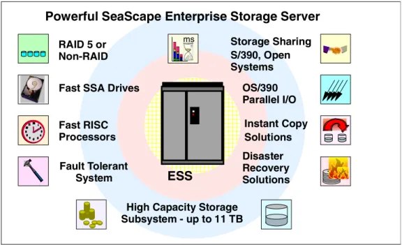
Figure 1. IBM’s New Storage Subsystem
The Enterprise Storage Server (ESS) is the latest IBM storage product to be developed using IBM’s Seascape architecture. It provides all the open systems functions of the Versatile Storage Server, and now with System/390 attachment, it provides all the functions of the 3990 Storage Control too—and a lot more. We have some exciting new functions for both the S/390 customer and the open systems customer. For S/390 we have some new features that significantly enhance performance. These features, which together with OS/390 software deliver a new world to the S/390 storage environment, are probably the biggest change since disk caching was introduced. For the non-mainframe customer, we have delivered features that were previously only available on mainframe
storage, functions that will enable you to better manage your data. For both customers we have capacity and performance to meet the largest of your requirements.
The Seascape architecture is the key to the development of IBM’s storage products both now and in the future. Seascape allows IBM to take the best of the technologies developed by the many IBM laboratories and integrate them to produce flexible and upgradable storage solutions—technologies such as the PowerPC, the Magstar Tape drives and IBM’s award-winning Ultrastar disk drives. Serial interconnect technology, SSA, now delivering a 160 MB/sec data rate, is used within the Seascape architecture to connect the processors and internal disks to ensure high performance and availability. Seascape also allows us to adapt to new technologies quickly, such as Fibre Channel and S/390 FICON.
IBM has already delivered Seascape solutions with the Virtual Tape Server, the Network Storage Manager and the Web Cache Manager. The Versatile Storage Server was the first of the Seascape disk servers; now we have announced the Enterprise Storage Server, the follow-on to the VSS, utilizing the latest
Powerful SeaScape Enterprise Storage Server
RAID 5 or Non-RAID Fast SSA Drives
High Capacity Storage Subsystem - up to 11 TB Fault Tolerant System Disaster Recovery Solutions Storage Sharing S/390, Open Systems Fast RISC Processors OS/390 Parallel I/O Instant Copy Solutions ms
ESS
technology and taking advantage of the Seascape architecture’s flexibility to upgrade and replace components easily and quickly.
Introduction 3
1.1 Positioning of the Enterprise Storage Server
Figure 2. Positioning of the Enterprise Storage Server
The Enterprise Storage Server is the natural successor to the IBM 3990. It provides all the functions that were available on the 3990, including peer-to-peer remote copy (PPRC), extended remote copy (XRC), and concurrent copy. For the many customers that have installed the RAMAC Virtual Array (RVA), with its revolutionary log structured file (LSF) architecture, we have protected their investment in this technology too. The Enterprise Storage Server will, in the future, implement an LSF architecture. You will even have the choice of how much capacity you have under an LSF arrays and how much under the existing ESS design. If you have implemented SnapShot, then your investment in the function will be protected on ESS—initially by a function (FlashCopy) that will provide fast, real, time zero (T0) copies; and later when we have LSF, by the ESS SnapShot equivalent. We have made the software interface transparent to allow you to exploit RVA SnapShot, ESS FlashCopy or even Concurrent Copy without changing your procedures.
The Remote Copy functions available on both 3990 and RVA are available on the Enterprise Storage Server with the same operational interfaces, allowing you to mix, for example, PPRC on 3990, RVA, and ESS in the same installation. The Enterprise Storage Server also supports TPF, providing a very high performance solution for the airlines, and other TPF users who need a high performance, high availability solution to support their critical business applications.
For the open systems or AS/400 customer, we have delivered the next generation of VSS. The Enterprise Storage Server builds upon the VSS and adds more function, more capacity, and more attachment capability. We have protected your investment in VSS by enabling you to attach it to an Enterprise Storage Server and utilize all its installed capacity. In addition, we have introduced a remote
RAMAC Virtual Array T82 SnapShot RAMAC Scalable Array RAMAC 3 Array InfoSpeed Cross Platform Extension ESS 2105 Seascape Powerful Storage Server
Universal Data Access
Snap-in Building Blocks 7133 RAMAC Virtual Array X82 Versatile Storage Server Advanced 7133 3990
mirroring capability for disaster recovery. Utilizing IBM’s ESCON technology, you can locate the remote site at distances of up to 103 kilometers from the primary location.
If you have invested in IBM 7133 (the D40 and 020), we can install your drawers attached through a VSS expansion rack, and protect your current investments.
Introduction 5
1.2 Benefits
The ESS can help you achieve your business objectives in many areas; it provides a high-performance, high-availability subsystem with flexible storage that can be configured according to your requirements.
Storage Consolidation
The Enterprise Storage Servers high performance, attachment flexibility, and large capacity enable you to consolidate your data from different platforms onto a single high performance, high availability box. Storage consolidation can be the first step towards server consolidation, reducing the number of boxes you have to manage and allowing you the flexibility to add or assign capacity when and where it is needed. ESS supports all the major server platforms, from S/390 to AS/400, Windows NT to many of the flavors of UNIX, as shown in Figure 3. With a capacity of up to 11TB, and up to 32 host connections, an ESS can meet both your high capacity requirements and your performance expectations.
Figure 3. Storage Consolidation
Performance
The Enterprise Storage Server is designed as a high performance storage solution and takes advantage of IBM’s leading technologies. In today’s world, where your business can reach global markets through e-business, you need business solutions that can deliver high levels of performance continuously every day, day after day. You also need a solution that can handle different workloads simultaneously, so you can run your Business Intelligence models, your large databases for Enterprise Resource Planning (ERP), and your online and Internet transactions alongside each other with minimal impact. Figure 4 on page 6 shows some of the performance enhancing capabilities of the ESS.
S/390
AS/400
Unix
Windows NT
ESS
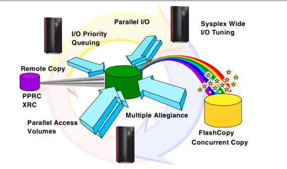
Figure 4. Enterprise Storage Server Capabilities
Some of you may be concerned about running S/390 and Open systems
workloads together on an Enterprise Storage Server, because of the often widely differing workload characteristics. Typically S/390 workloads are cache-friendly and take advantage of large caches, whereas the open systems workloads are often very cache-unfriendly. For the S/390 workload, we have sophisticated cache management algorithms and a large cache. For the workloads that cannot take advantage of cache, we have high performance disk arrays with fast disks and serial interconnect technology. So whatever the workload, even mixed workloads, ESS delivers high performance.
Another example of why an Enterprise Storage Server can deliver on
performance is the RAID design; the RAID function is managed not by the main RISC processors in the ESS, but at the disk loop level. Up to 16 RAID functions can be performed simultaneously, delivering fast response times and high throughput.
OS/390 Parallel Sysplex I/O Management
For the OS/390 Parallel Sysplex customer, the Workload Manager (WLM) controls where work is run and optimizes the throughput and performance of the total system. Until now, WLM management of the I/O has been limited. With ESS we have some exciting new functions that allow the Workload Manager to control I/O across the Sysplex. These functions, described in detail later in this book, include parallel access to both single system and shared volumes and the ability to prioritize the I/O based upon your WLM goals. The combination of these features can significantly improve performance in a wide variety of workload environments. Remote Copy PPRC XRC FlashCopy Concurrent Copy I/O Priority Queuing Parallel I/O Multiple Allegiance Parallel Access Volumes Sysplex Wide I/O Tuning
Introduction 7 Figure 5. Disaster Recovery and Availability
The Peer-to-Peer Remote Copy function is now recognized as the future for disaster recovery in the S/390 Sysplex world by all the leading S/390 storage vendors. PPRC together with enhancements to OS/390 and Geographically Dispersed Parallel Sysplex (GDPS) lead the industry in high availability solutions. Recent Gartner1analysis shows a Parallel Sysplex solution as having, on average, less than 10 minutes outage per year. With GDPS and PPRC, IBM is bringing the recovery time following a disaster into minutes rather than days. The PPRC solution is available with the Enterprise Storage Server for UNIX and Windows NT. Management of the PPRC setup is through the ESS Specialist Web interface. Now we have disaster solutions for many platforms using a simple and easy-to-use interface.
Finally, we have enhanced Extended Remote Copy (XRC), the OS/390 disaster recovery solution that you can use over long distances. Enhancements to XRC delivered by the Enterprise Storage Server eliminate the need to recopy the data should the Data Mover function fail. Now the ESS will keep track of changes on the primary storage, and the Data Mover will just copy the changed data to the secondary storage after it is restarted.
Instant Copy and Your Backups
For all environments today, taking backups of your data probably takes you a long time. Even though we have high availability storage that is fault tolerant and protected by RAID, you still need to take backups to protect your data from logical errors and disasters. Backups are often taken outside prime shift because of the impact to normal operations. Databases must be closed to create consistency and data integrity, and the online systems are normally shut down.
1 Gartner Research Note 29 October 1998. Platform Availability Data: Can you Spare a Minute?
ESCON
PPRC - Synchronous Remote Copy XRC - Asynchronous Remote Copy (OS/390 only)
Protect your Data
S/390 Unix Windows NT Web Inter-face
To help reduce the impact of backups and other copy requirements, IBM introduced an instant copy function, called SnapShot on S/390 and the RAMAC Virtual Array (RVA). SnapShot used the unique architecture of the RVA to be able to take a volume or dataset copy almost instantaneously. Then you could take your backups from the copies in parallel with normal processing. This enabled RVA customers to save valuable time—a study has shown an average of four hours—out of the backup window, not only saving time, but also requiring almost no additional capacity to take the copies.
The Enterprise Storage Server, although it does not have the architecture that can perform instant copies without using disk capacity today, does have an equivalent function called FlashCopy. This new function not only applies to the S/390, but also to all the other platforms. For the OS/390 customer, we have made the interface to invoke FlashCopy transparent—you can use the IBM utilities you use today, and they will automatically select the FlashCopy feature of ESS, or SnapShot on RVA, or even Concurrent Copy on 3990. This protects any investment you make in procedures and automation, no matter which IBM storage solution you may have.
Data Sharing
Data Sharing is one of those areas where there has been lots of talk, but not always much delivered. We at IBM have defined three levels of data sharing: 1. Partitioned Storage:
Data is consolidated onto a common storage box, but the capacity is partitioned between the different attached hosts.
An example of this is the VSS and also the ESS as shown in Figure 6. The Enterprise Storage Server can attach to S/390, AS/400, Unix systems, and Windows NT. The advantage of ESS is that storage can be
dynamically added to any of the hosts, or reallocated from one host to another. S/390 ESCON SC SI Unix W indow s N T IB M D ata Path Optimizer InfoSpeed ESCON SCSI Up to 32 Host Ports ESCON
Introduction 9 2. Data Copy Sharing:
Data is copied from one platform to another and at the same time may undergo some form of translation and reformatting so that the other platform can understand the data.
An example of this is the IBM InfoSpeed, which transfers data at channel speed between OS/390 and UNIX or NT.
3. True Data Sharing:
True data sharing between homogeneous hosts has been available for many years; for example OS/390 IMS Datasharing has been available for more than 15 years. Similar data sharing capabilities exist on Compaq VMS and Sun systems.
In terms of datasharing with database access from homogeneous hosts today, we have S/390 with DB2 and IMS/DL1. UNIX systems can use Oracle Parallel Server to share data. But there are as yet no cases where we can share databases between heterogeneous systems. The issue to be resolved is not a hardware one—it is easy to physically share disks—but rather, a software one. The software on each platform must be able to understand the format and content of the data and manage database integrity, through common locks, logs and recovery facilities.
Sharing of non-database data is easier providing both parties understand the content of the data. Agreeing on a common format will be a first step to true datasharing. The Seascape architecture of the Enterprise Storage Server will enable us, in the future, to include powerful new functions to start us down the path towards true datasharing. ESS has the powerful, intelligent UNIX based RISC processors to enable us to achieve this.
Storage Area Networks Announcement Preview
For the open systems customer who is looking at Storage Area Networks and Fibre Channel, the ESS supports a variety of Fibre Channel attachment options. Initially support is provided by the IBM SAN Data gateway which provides support for Fibre Channel attachment to ESS SCSI ports. As servers migrate from SCSI to Fibre Channel, the IBM gateway strategy allows the ESS to support this migration while protecting customer investments.
IBM is previewing plans for the ESS to support native Fibre Channel, providing a basis for future development of full SAN exploitation in areas such as disk pooling, file pooling, and copy services. Up to 16 Fibre Channel ports will be available on an ESS. Each port will support point-to-point and fabric (switched) connections as well as FCAL. Fibre Channel ports also support FICON, the Fibre Channel interface for S/390 servers. Fibre Channel ports will be available as an upgrade option for installed ESSs.
The preview information in the preceding paragraph provides insight into IBM plans and direction. General availability, prices, ordering information, and terms and conditions will be provided when the specific ESS product features are announced.
IBM has more than eight years production experience with fiber, its ESCON technology being based on early Fibre Channel developments. For the S/390 customer, ESCON already delivers many of the advantages of SANs, and with the introduction of FICON (S/390 I/O protocols running over Fibre Channel), S/390 will take advantage of the higher data rates that FC offers too. Figure 7 on page 10 shows how the ESS participates in a SAN.
The key to SANs is their management. In the ESCON SAN environment, we manage the infrastructure by using System Automation for S/390, and we manage the data with DFSMS/MVS. In the UNIX and NT environments, we have the Storwatch range of products that also manage the fiber infrastructure and the storage capacity, as well as the performance measurement information.
Figure 7. Storage Area Networks
Any Server to Any Storage
LAN
Hub
SAN Data Gateway
adapters bridges
switches
FC SAN
Introduction 11
1.3 Statement of Direction
Figure 8. Statements of Direction
IBM plans continuing growth and enhancements for the ESS, and will make these enhancements available as upgrades to installed ESSs.
• Continued performance enhancements by utilizing faster, more efficient, and higher bandwidth processing engines
• Increased cache capacity
• Significantly increased maximum storage capacity
• Implementation of a virtual architecture similar to that used by the RAMAC Virtual Array (RVA), enabling many storage system enhancements such as:
• Improved use of space through compression and the storage of only the written data
• A more efficient FlashCopy, enabling many copies to be made available in less time
• FlashCopy elimination of physical storage space required by a physical copy
• Easier storage management
This statement represents IBM’s current intent and is subject to change or withdrawal.
Performance enhancements
Increased cache size
Increased storage capacity
Virtual Architecture
Data compression
Efficient FlashCopy for multiple copies
No physical space required for FlashCopy
Easy storage management
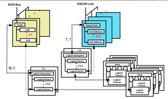
1.3.1 Terminology
Figure 9. Terminology
Before we start looking at the hardware, architecture, and configuration, we will briefly cover the terminology we use. For those who are not familiar with S/390, we point out the terminology used by ESCON. For those who are not familiar with UNIX or NT, we describe the SCSI Terminology.
1.3.2 S/390
First we explain the S/390 terminology shown in the Terminology diagram. 1.3.2.1 ESCON Channel
The ESCON channel is a hardware feature on the S/390 that controls data flow over the ESCON Link. An ESCON channel is usually installed on an ESCON channel card which may contain up to four ESCON channels.
1.3.2.2 ESCON Port
The ESCON port is the physical interface into the ESCON Channel. An ESCON port has an ESCON connector interface. You have an ESCON port wherever you plug in an ESCON Link.
1.3.2.3 ESCON Link
An ESCON link is the fiber connection between the S/390 and the ESS. An ESCON link can also exist between a S/390 processor and an ESCON Director (fiber switch), and between an ESCON Director and the ESS (or other ESCON capable devices).
S/390
ESS
ESCON port ESCON Link ESCON Adapter ESCON port ESCON channelUNIX/NT
ESS
SCSI port SCSI busSCSI Host Adapter SCSI port SCSI Adapter CKD
FB
VolumeDisks
Count Key Data Fixed Block architectureIntroduction 13 In OS/390 we define the volumes as having particular characteristics. They can either represent a 3390 track format (56K) or 3380 track format (47K), and the number of cylinders on a volume can be set to match a specific 3380 or 3390 model. For example, a 3390 Model 3 has 3339 cylinders, and a 3390 Model 9 has 10017 cylinders (a cylinder is 15 tracks).
1.3.2.5 CKD
Count key data (CKD) is the disk architecture used by S/390. Because data records can be variable length, they all have a count field that indicates the record size. The key field is used to enable a hardware search on a key, however, this is not generally used for most data anymore.
ECKD is a more recent version of CKD that uses an enhanced S/390 channel command set.
The commands used by CKD are called Channel Command Words (CCWs); these are equivalent to the SCSI commands.
1.3.3 UNIX and Windows NT
Let us now look at the terminology used by UNIX and NT systems with SCSI disks.
1.3.3.1 SCSI Adapter
A SCSI Adapter is usually a card installed in a host system. It connects to the SCSI bus through a SCSI connector. There are different versions of SCSI, some of which can be supported by the same adapter. The two that are supported by the ESS are:
• SCSI-Fast-Wide 20 MB/sec • Ultra-SCSI-Wide
40 MB/sec
The protocols that are used on the SCSI adapter (the command set) can be either SCSI-2 or SCSI-3 (equivalent, for example, to CKD and ECKD on S/390). 1.3.3.2 SCSI Port
A SCSI Port is the physical interface into which you connect a SCSI cable. The physical interface varies, depending on what level of SCSI is supported. 1.3.3.3 SCSI Bus
The SCSI bus is the path linking all the devices that are chained together on the same SCSI adapter. Each device on the bus is connected to the next one by a SCSI cable, and at the last device on the bus, there is a terminator. (From the S/390 view, this is almost identical to the S/390 parallel channel design.) 1.3.3.4 SCSI Host Adapter
The ESS has a SCSI Host Adapter (you will see this referred to as the Host Adapter or HA in the book). The SCSI Host Adapter is connected to the SCSI bus and accepts the SCSI commands that are sent by the host system.
1.3.3.5 Disks
Disks (or maybe logical disks) are the logical representations of a SCSI disk as seen from the UNIX or NT system. In reality, a disk may span multiple physical disks, and the size of the disk is set when the disk is defined to the ESS. 1.3.3.6 Fixed Block Architecture
SCSI disks use a fixed block architecture, that is, the disk is arranged in fixed size blocks or sectors. With an FB architecture the location of any block can be calculated to retrieve that block. The concept of tracks and cylinders also exists, because on a physical disk we have multiple blocks per track, and a cylinder is the group of tracks that exists under the disk heads at one point in time without doing a seek.
In the ESS, all the tracks and cylinders are logical; they are mapped onto arrays and disks which may have very different track and cylinder sizes.
© Copyright IBM Corp. 1999 15
Chapter 2. Hardware
This chapter covers the physical hardware components of the Enterprise Storage Server (ESS). These include the models, expansion racks, and use of existing VSS drawers. We will describe the internal device adapters and connections to the host systems.
2.1 IBM Enterprise Storage Server Overview
Figure 10. IBM Enterprise Storage Server Overview
The IBM Enterprise Storage Server is a high performance, high availability, high capacity storage subsystem. It contains two 4-way RISC processors with 6 GB of cache and 384 MB of non-volatile storage to protect from data loss. The ESS has a maximum capacity of over 11 TB with the second frame attached. Connectivity to S/390 is through up to 32 ESCON channels; and to UNIX, AS/400, or NT hosts, through up to 32 SCSI interfaces; or a combination of the two. In the future, the ESS will support both S/390 Fiber Channel (FICON) and Fibre Channel Protocol (FCP), including Fiber Channel Arbitrated Loop (FCAL) and FC-switched for open systems.
Currently you can attach to a FICON channel using the 9032 ESCON Director, and to a Fibre Channel network using the IBM SAN Data Gateway.
Two 4-way RISC processors
Up to 11 TB capacity
8 x 160 MB/sec SSA loops
6 GB cache
384 MB NVS
32 ESCON / SCSI / mixed
Fibre Channel and FICON
planned
Hardware 17
2.2 ESS Models and Expansion Rack
Figure 11. ESS Models and Expansion Racks
2.2.1 Enterprise Storage Server Models
There are two models of the IBM Enterprise Storage Sever shown in Figure 11: • The IBM 2105-E20 Enterprise Storage Server
This model has two three-phase supplies and supports the full complement of 128 disks in two 2105 cages.
• The IBM 2105-E10 Enterprise Storage Server
This model has two single-phase power supplies and, because of this, has limited capacity in terms of disk arrays. Only 64 disks can be installed in the base rack. These occupy a single 2105 cage.
A 2105-E10 can be upgraded to a 2105-E20.
Only 2105 cages can be installed in the E10 and E20.
2.2.2 ESS Expansion Rack feature 2100
This rack attaches to the 2105-E20 only and uses three-phase power supplies. Up to four ESS cages can be installed in the 2105-E20 expansion rack. This gives a maximum of 256 disks in the four cages.
Enterprise Storage Server Models
2105-E20 Enterprise Storage Server
Three phase power supply
Supports maximum capacity of 128 disks in base rack Feature for expansion rack
2105-E10 Enterprise Storage Server
Single-phase power supply
Restricted to a maximum of 64 disks in base rack
ESS Expansion Rack Feature
2105-E20 ESS expansion rack feature
Three-phase power supply
Supports up to 256 disks in ESS cages
Enterprise Storage Server Models
2105-E20 Enterprise Storage Server
Three phase power supply
Supports maximum capacity of 128 disks in base rack Feature for expansion rack
2105-E10 Enterprise Storage Server
Single-phase power supply
Restricted to a maximum of 64 disks in base rack
ESS Expansion Rack Feature
2105-E20 ESS expansion rack feature
Three-phase power supply
2.3 ESS Support of IBM 2105-B09/100
Figure 12. ESS Support of IBM 2105-B09/100
2.3.1 IBM 2105-B09 Versatile Storage Server
The IBM 2105-B09 Versatile Storage Server disk capacity can be used by an IBM 2105 Enterprise Storage Server. All the drawers in the VSS can be attached to an ESS, giving a capacity of 64 disks (in four drawers). Only 7133-D40 and
7133-020 drawers are supported.
The attachment of an existing VSS allows a customer to protect the investment made in VSS disk capacity.
Attaching the VSS to an ESS requires that you configure the Device Adapters to attach the VSS drawers. This is described in section 4.4.2, “The Device Adapters” on page 78.
Note:The processors in the VSS are not used once the VSS drawers are attached to the ESS. They remain in the rack and provide stability.
2.3.2 IBM 2105-100 Versatile Storage Expansion Rack
Up to three IBM 2105-100 VSS Expansion Racks can be attached to an
Enterprise Storage Server. Each expansion rack supports up to seven 7133-D40 or 7133-020 Drawers. The drawers must contain full configurations of 16 disks and are attached to the ESS Device Adapters. See section 4.3, “Mixing with 2105-B09 / 100 Racks” on page 77 for more details.
Maximum capacity for any combination of 2105-E10 or E20 and 2105-B09 or 2105-100 Expansion Racks is 384 disks.
Neither the 2105-B09 nor the 2105-100 can be used if the ESS already has a 2105-E20 expansion rack attached.
2105-B09 Versatile Storage Server
SSA disks attached to ESS Device Adapters VSS processors disabled
Capacity 64 disks
2105-100 Versatile Storage Expansion Rack
SSA disks attach to ESS Device Adapters Up to 112 disks supported
Up to 3 racks can be attached to a ESS
Hardware 19
2.4 Photograph of the IBM Enterprise Storage Server
Figure 13. Photograph of the IBM Enterprise Storage Server
Shown in Figure 13 is a photograph of a 2105-E20 Enterprise Storage Server (ESS) with the covers removed. At the top of the frame are the disks, below that the DC power supplies, and directly below these are the RISC processors. Just below the processors are the Device Adapters and the Host Adapters and at the bottom of the frame are the AC power supplies and batteries.
The photo clearly shows the two clusters, one on each side of the frame.
The height of the ESS is 70.7 inches (1.793 meters), width is 54.4 inches (1.383 meters), and depth is 35 inches (0.89 meters), without its top cover. The ESS requires a raised floor environment.
2.5 ESS Components
Figure 14. ESS Components
This diagram shows a 2105-E20 Enterprise Storage Server and its major components. As you can see, the ESS rack consists of two clusters, each with their own power supplies, batteries, host adapters, device adapters, processors, and disks.
At the top of each cluster is an ESS cage. This provides slots for up to 64 disks, 32 in the front and 32 in the back of each cage. If this were a 2105-E10, it would have only one ESS cage located above the left cluster.
In the following sections we will look in detail at each of the major components.
Cages
DC Power Supplies
RISC Processors and
Device Adapters
Host Adapters
Power
Hardware 21
2.6 Components — ESS Cages
Figure 15. Components — Enterprise Storage Server Cages
2.6.1 Cages
The Enterprise Storage Server cages provide a higher disk capacity in the ESS rack when compared to 7133 drawers. Some common functions have been provided at the rack level. For example, a single battery provides power to all the disks should a power outage occur. Similarly, a central fault tolerant rack power is used for all the racks, removing the need for the drawer level power supplies found on the 7133 and the VSS.
Disks can be installed in the cages in groups of 8. These are called disk 8-packs. Two disk 8-packs are required in either the 2105-E10 or 2105-E20 to provide a minimum configuration. The cage provides the power connections for each 8-pack which comes packaged into a slimline case and slides into a slot in the cage. Empty slots have a protective flap that controls the airflow over the disks. Each group of 8 disks is configured as a RAID Rank of either 6 Data + Parity + Spare, 7 Data + Parity, or JBOD (Just a Bunch Of Disks)—No Parity.
2.6.2 Expansion Rack
The IBM 2105-E20 expansion rack supports from 1 to 4 ESS cages. Each cage supports up to 64 disks in groups of 8, giving a maximum capacity of 256 disks in 4 cages.
Cages
E20 1-2 Cages, E10 1 Cage
Supports up to 64 disks/cage
Disks installed in groups of 8 only
('8-packs')
8 disks = 1 RAID rank
6 + Parity + Spare or 7 + ParityExpansion Rack
1-4 ESS cages / E20 expansion rack
Cage - 64 disks (32 front/32 back)
2.7 Components — Disks
Figure 16. Components — Disks
The maximum capacity of the ESS is 384 disks—128 disks in the base unit and 256 disk in the expansion rack. Using 36 GB disks and RAID-5, this gives a total usable capacity of approximately 11 TB.
The minimum configuration of an 2105-E10 or E20 is 16 disks of 9.1 GB capacity in two 8-packs in an ESS cage. All 8-packs must be ordered and installed in pairs.
The disks installed in the ESS are all state-of-the-art IBM magnetoresistive head technology. The disks support all the advanced disk functions, including
predictive failure analysis (PFA). For details about IBM disk technology, see the redbookIBM Versatile Storage Server, SG24-2221.
2.7.1
2105 8-Pack
The ESS 8-pack is the basic unit of capacity within the ESS base and the ESS expansion rack. These 8-packs are ordered and installed in pairs. Each 8-pack is set up initially as a RAID Rank (6+P+S or 7+P) or as a JBOD (Just a Bunch Of Disks). You have the choice of three different disks for use within an 8-pack. Each disk uses the 40 MB/sec SSA interface.
• 9.1 GB - 10,000 RPM
Use this disk size for the highest performance RAID Ranks.
2105 8-pack
Installed in 2105 cages
40 MB/sec SSA disks
9.1 GB 18.2 GB 36.4 GB
7133-D40 Drawer
*
16 disks/drawer only
40 MB/sec
4.5 GB 9.1 GB 18.2 GB 36.4 GB7133-020 Drawer
*
16 disks/drawer only
20 MB/sec only
4.5 GB 9.1 GB7133-010 Not Supported
Hardware 23
It is required that all disks attached to the same SSA loop should be of the same type, capacity, and loop performance. The reason for this is that sparing
operations take place within the loop (not within RAID Rank), so that over time, as failed disks are replaced, the RAID Ranks within the loop become intermixed. Mixing different loop speeds on the same loop would slow the loop down to the slowest speed.
You cannot mix 8-packs and 7133 drawers on the same loops.
2.7.2
7133-D40 Drawer
The 7133-D40 Drawer can be attached to the base unit from an existing 2105-B09 or 2105-100 rack. 7133-D40 Drawers in a 7015-R00 rack cannot be attached directly to an ESS. They must be removed and installed in a 2105 VSS Model 100 expansion rack. This restriction is because the ESS cannot manage the power sequencing of the 7015-R00 rack.
The 7133-D40 Drawer must contain the full 16 disks to be supported by an ESS. Disks supported by ESS in the 7133-D40 Drawer are:
• 4.5 GB - 7200 RPM
• 9.1 GB - 7200 or 10000 RPM • 18.2 GB - 7200 or 10000 RPM • 36.4 GB - 7200 RPM
The 4.5 GB disks in the 7133-D40 drawer only operate at 20MB/sec. Note that the 7133-D40 Drawer is not supported by ESS until after General Availability of the IBM Enterprise Storage Server.
2.7.3 IBM 7133-020 Drawer
The 7133-020 Drawers are supported by an ESS only when installed in the 2105-B09 VSS or in the 2105-100 VSS Expansion rack.
The 7133-020 operates at 20 MB/sec on its SSA interfaces, and should not be mixed on the same loop as 40MB/sec disks. Mixing the disks will impact the performance of all the disks on the loop.
Disks supported by the ESS in the 7133-020 Drawer are: • 4.5 GB - 7200 RPM
• 9.1 GB - 7200 RPM
Note that the 7133-020 Drawer is not supported by ESS until after General Availability of the IBM Enterprise Storage Server.
2.7.4 IBM 7133-010
2.8 Components — RISC Processors
Figure 17. Components — RISC Processors
2.8.1 Processors
The Enterprise Storage Server is a Seascape architecture subsystem and uses high performance IBM RISC processors to manage its operations.
Each cluster has a 4-way SMP RISC processor running at 332 MHz.
2.8.2 Cache
Cache is used to store both read and write data to improve ESS performance to the attached host systems. Each cluster has its own non-shared cache of 3 GB. Cache operation is described in section 3.10, “Cache and Read Operations” on page 50.
2.8.3 Non-Volatile Storage (NVS)
NVS is used to store a second copy of write data to ensure data integrity, should we get a power failure or a cluster failure and we lose the cache copy. The NVS for cluster 1 is located in the cluster 2 frame and the NVS for cluster 2 is located in the cluster 1 frame. Should a cluster fail, the remaining cluster can access the NVS of the failed cluster and destage all the unwritten data. This process ensures that no data is lost even in the event of a component failure.
Each cluster has 192 MB of NVS.
Each NVS is protected by a battery that protects the data in the case of a total power outage. The battery protects the data for up to 7 days.
Two 4-way SMP RISC processors
332 MHz Processors
6 GB Cache
3 GB cache per processor Managed independently
384 MB NVS
192 MB NVS per processor Cluster 1 NVS in Cluster 2 frame Cluster 2 NVS in Cluster 1 frame Non-volatile battery backup for 7 days
Hardware 25
2.9 Components — Device Adapters
Figure 18. Components — Device Adapters
2.9.1 SSA160 Device Adapters
The Enterprise Storage Server uses the latest SSA160 technology in its device adapters. With SSA160, each link operates at 40 MB/sec, giving a total
bandwidth of 160 MB/sec across the loop. Each device adapter card supports two independent SSA loops, giving a total bandwidth of 320 MB/sec per adapter card. There are four pairs of device adapters in an ESS providing a total disk
bandwidth capability of 1,280 MB/sec. One adapter from each pair of adapters is installed in each cluster as is shown in Figure 18.
The SSA loops are between adapter pairs, which means that all the disks can be accessed by both clusters. During the configuration process each rank (RAID array or JBOD) is configured to be normally accessed by only one of the clusters. Should a cluster failure occur, the remaining cluster can takeover all the disks on the loop.
2.9.2 Disks per Loop
Each loop supports up to 48 disks, and each adapter pair supports up to 96 disks. There are four adapter pairs supporting 384 disks in total.
The diagram in Figure 18 is a logical depiction of a single loop with 48 disks, (the RAID ranks are actually split across two 8-packs for optimum performance). There are 6 RAID Ranks labelled A-F. Ranks A and B both have spare disks that are used across the loop in case of a disk failure. The failed disk is replaced and becomes the new spare. Over time the disks in the RAID Ranks on the loop become mixed. So it is not possible to remove an 8-pack or RAID-Rank without deleting all the data on the loop.
SSA 160 Device Adapters
4 DA pairs per Subsystem 4 x 40 MB/sec loop data rate 2 Loops per Device Adapter pair
Up to 48 disks per loop
No mix of '8-packs' and drawers Each group of 8 is
RAID-5 array, 6+P+S or 7+P or 8 JBOD
2 spares per loop
No mix of capacity, data-rate or RPM per loop DA DA A A A A A A S A B B B B B B S B C C C C C C C C D D D D D D D D E E E E E E E E F F F F F F F F 48 disks
For a JBOD configuration, each disk in the 8-pack is independent and is set up individually.
It is recommended that all disks on the loop be of the same type, speed, and size. 7133-D40 and 7133-020 Drawers can be used in the loops—all the disks in one drawer will be on the same loop. The drawers must have all 16 disks installed.
Hardware 27
2.10 Components — SSA Loops
Figure 19. Components — SSA Loops
2.10.1 SSA Operation
SSA is a high performance, serial connection technology for disk drives. SSA is a full-duplex loop based architecture, with two physical read paths and two physical write paths to every disk attached to the loop. Data is sent from the adapter card to the first disk on the loop and then passed around the loop by the disks until it arrives at the target disk. Unlike bus based designs, which reserve the whole bus for data transfer, SSA only uses the part of the loop between adjacent disks for data transfer. This means that many simultaneous data transfers can take place on an SSA loop, and it is one of the main reasons that SSA performs so much better than SCSI. This simultaneous transfer capability is known as spatial reuse. Each read or write path on the loop operates at 40MB/s, providing a total loop bandwidth of 160MB/s.
2.10.2 Loop Availability
The loop is a self-configuring, self repairing design which allows genuine hot-plugging. If the loop breaks for any reason, then the adapter card will automatically reconfigure the loop into two single loops. In the ESS, the most likely scenario for a broken loop is if the actual disk drive interface electronics should fail. If this should happen, the adapter card will dynamically reconfigure the loop into two single loops, effectively isolating the failed disk. If the disk were part of a RAID array, the adapter card would automatically regenerate the missing disk using the remaining data and parity disks to the spare disk. Once the failed disk has been replaced, the loop will automatically be reconfigured into full duplex operation, and the replaced disk will become a new spare.
SSA operation
4 links per loop
2 read and 2 write simultaneously in each direction
40 MB/sec on each link
Loop Availability
Loop reconfigures itself
dynamically
Spatial Reuse
Up to 8 simultaneous operations
to local group of disks (domains)
DA read readwrite write DA read write DA DA
2.10.3 Spatial Reuse
Spatial reuse allows domains to be set up on the loop. A domain means that one or more groups of disks “belong” to one of the two adapter cards, as is the case during normal operation. The benefit of this is that each adapter card can talk to its domains (or disk groups) using only part of the loop. The use of domains allows each adapter card to operate at maximum capability because it is not limited by I/O operations from the other adapter. Theoretically, each adapter card could drive its domains at 160MB/s, giving 320MB/s throughput on a single loop! The benefit of domains may reduce slightly over time, due to disk failures causing the groups to become intermixed, but the main benefits of spatial reuse will still apply.
If a cluster should fail, the remaining cluster device adapter will own all the domains on the loop, thus allowing full data access to continue.
Hardware 29
2.11 Components — Host Adapters
Figure 20. Components — Host Adapters
2.11.1 Host Adapter Bays
The Enterprise Storage Server has four Host Adapter (HA) bays, two in each cluster. Each bay supports up to four host adapters. Each HA supports two SCSI ports or two ESCON channels
Each host adapter can communicate with either cluster, so there is no
requirement to install a host adapter in a cluster 1 bay just to attach to cluster 1. To install a new host adapter card, the bay must be powered off. For this reason, it is important to spread the host connections across all the adapter bays; this will minimize the impact, particularly for ESCON, where you would normally configure multiple paths to the ESS. For example, if you have four ESCON links to a host, each connected to a different bay, then the loss of a bay for repair or upgrade would only impact one link out of four.
For an AIX or NT host, you can use the new IBM Data Path Optimizer (DPO) to attach multiple paths to the same host. The DPO will manage up to 16 paths, handling errors and distributing the I/O load over all available paths.
2.11.2 ESCON
From zero to 32 ESCON channels are supported by the ESS, two per ESCON host adapter. Both 17 MB/sec and 10 MB/sec ESCON channel speeds are supported.
It is recommended that if you are using less than the maximum number of ESCON adapters, that you spread the ESCON adapters equally across the four adapter bays. This is because each adapter bay is connected to a different PCI bus, and by spreading the adapters across the four busses, you optimize performance.
Host Adapter bays
Four bays
Four host adapters per bay
ESCON
0-32 ESCON channels
2 ESCON channels/host adapter
SCSI
0-32 SCSI ports
2 SCSI ports/host hdapter
Mixed ESCON & SCSI
Any combination of host adapters
(each adapter is 2 ports/channels)
2.11.3 SCSI
From zero to 32 SCSI ports are supported by the ESS, two per SCSI host adapter.
Each port is an FW Differential Ultra SCSI and supports both Ultra SCSI (40MB/sec) and SCSI-2 (20MB/sec).
The same recommendation applies to SCSI as we mentioned above for ESCON: Spread the SCSI adapters across all the adapter bays equally.
2.11.4 Mixed ESCON and SCSI
Any combination of SCSI and ESCON host adapters are supported, up to a combined maximum of 16 adapters (32 ports).
Hardware 31
2.12 Host Adapters — ESCON
Figure 21. Host Adapters — ESCON
2.12.1 ESCON Host Adapters
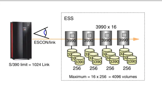
Each ESCON Host Adapter is connected to both clusters. An Enterprise Storage Server emulates 0, 8 or, 16 of the 3990 Logical Control Units. Half the LCUs are in cluster 1 and half in cluster 2. Because the ESCON adapters are connected to both clusters, each adapter can address all 16 LCUs.
More details on the CKD logical structure can be found in 3.15, “Logical Subsystem — CKD” on page 58.
2.12.2 Logical Paths
An ESCON link consists of two fibers—one for each direction—connected at each end by an ESCON connector to an ESCON port.
Each ESCON adapter card supports two ESCON ports or links, and each port supports 64 logical paths. With the maximum of 32 ESCON ports, the maximum number of logical paths is 2048.
2.12.3 ESCON Distances
Apart from the standard 2 km with 50 micron multimode fiber, and the 3 km with 62.5 micron multimode fiber, you can extend the distance at which you can operate the ESS to 103 km for PPRC—control unit to control unit. This distance can be achieved, for example, by using two IBM Optical Wave Division
Multiplexors (MuxMasters), each of which supports a distance of 50 km. Although the ESS will support distances of up to 103 km from host to control unit, this is not recommended for optimum performance.
ESCON Host Adapters
Each ESCON HA communicates with both clusters
Each ESCON channel can address all 16 Logical Control Unit images
Logical Paths
64 Logical Paths per ESCON link Up to 2048 Logical Paths per ESS
ESCON Distances
2 km with 50 micron LED 3 km with 62.5 micron LED
PPRC max of 103 km with Channel Extenders
2.13 Host Adapters — FICON/ESCON
Figure 22. Host Adapters — FICON/ESCON
2.13.1 FICON/ESCON Bridge Support
Currently, the Enterprise Storage Server supports FICON through the IBM 9032 Model 5 ESCON Director FICON Bridge card. This card supports up to 8 ESCON paths over a single Fibre Channel link.
2.13.2 Preview for Native FICON Support
As part of the Enterprise Storage Server announcement, IBM is previewing the support for Fibre Channel, including FICON, on the ESS.
FICON operates at 100 MB/sec bi-directional from a S/390 host to an ESS with a FICON adapter card.The FICON adapter will occupy one adapter slot and support a single FICON link. Also supported will be a Fibre Channel switch.
FICON/ESCON Bridge Support
Card on 9032 Model 5 ESCON Director
8 ESCON per FICON link
Preview for native FICON support
One FICON per Host Adapter slot
100 MB/sec bi-directional
FICON Bridge card 9032 Model 5S/390
FICONHardware 33
2.14 Host Adapters — SCSI
Figure 23. Host Adapters — SCSI
2.14.1 Ultra SCSI Host Adapters
The Enterprise Storage Server provides an Ultra SCSI interface with the SCSI-3 protocol and command set for attachment to UNIX systems, Windows NT, and AS/400. This interface also supports SCSI-2.
Each SCSI Host Adapter supports two SCSI interfaces. The interface is Fast Wide Differential and uses the VHDCI (Very High Density Connection Interface). VHDCI cables are orderable from IBM.
Hosts supported by the ESS SCSI interfaces include: • IBM RS/6000 • HP 9000 Series • Sun • IBM Netfinity • Data General • IBM AS/400
For a current list of supported SCSI Hosts, visit the IBM Web site at:
http://www.ibm.com/storage
The ESS SCSI interface supports 16 target SCSI IDs (the host requires one ID for itself) with up to 64 logical unit numbers (LUNs) per target (the SCSI-3 standard). The number of LUNs actually supported by the host systems listed above varies from 8 to 32. Check with your host supplier on the number supported by any specific level of driver or machine.
Ultra SCSI Host Adapters
Differential Fast Wide
40 MB/sec
2 ports per Host Adapter
Each HA communicates with both
clusters
Fibre Channel
Support through IBM SAN Data Gateway
Three FC link to four SCSI ports
Any-to-any connectivity
Preview of native Fibre Channel support
Fibre Channel IBM SAN Data Gateway UNIX UNIX SCSI