Research
Publication Date: 22 April 2005 ID Number: G00127434
© 2005 Gartner, Inc. and/or its Affiliates. All Rights Reserved. Reproduction and distribution of this publication in any form without prior written permission is forbidden. The information contained herein has been obtained from sources believed to be reliable. Gartner disclaims all warranties as to the accuracy, completeness or adequacy of such information. Although Gartner's research may discuss legal issues related to the information technology business, Gartner does not provide legal advice or services and its research should not be construed or used as such. Gartner shall have no liability for errors, omissions or inadequacies in the information contained herein or for interpretations thereof. The opinions expressed herein are subject to change without notice.
Use Best Practices to Design Data Center Facilities
Michael A. BellData centers seldom meet the operational and capacity requirements of their initial designs. The principal goals in data center design are flexibility and scalability, which involve site location, building selection, floor layout, electrical system design, mechanical design and modularity.
Publication Date: 22 April 2005/ID Number: G00127434 Page 2 of 26 © 2005 Gartner, Inc. and/or its Affiliates. All Rights Reserved.
TABLE OF CONTENTS 1.0 Introduction... 4 1.1 Density vs. Capacity ... 5 1.2 Rack Layout... 6 1.3 Rack Units ... 7 2.0 Design Criteria... 8
2.1 Critical Building Systems ... 9
2.2 Planning and Designing... 10
2.3 Location ... 11 2.4 Site... 12 2.5 Architecture ... 13 2.6 Power Distribution ... 14 2.7 Power Supply ... 15 2.8 Mechanical Systems... 16 2.9 Raised-Access Floor ... 17
2.10 Fire Detection and Suppression ... 18
3.0 Data Center Construction Costs — Tier 2... 19
3.1 Data Center Construction Costs — Tier 3... 20
4.0 Data Center Facilities Management Options:... 22
5.0 Conclusion ... 23
Appendix A. Conference Poll Results ... 23
Appendix B. Acronym Key... 25
LIST OF FIGURES Figure 1. The First Rule of Data Center Facilities: Design for Flexibility and Scalability ... 5
Figure 2. The Density vs. Capacity Debate... 6
Figure 3. Rack Layout Resulting Power Demands... 7
Figure 4. Use Rack Unit — The Primary Planning Factor... 8
Figure 5. Design Criteria: Scope and Redundancy ... 9
Figure 6. Critical Building Systems... 10
Figure 7. Engineering Plan and Space Design ... 11
Figure 8. Location Selection ... 12
Figure 9. Site and Building Selection Criteria... 13
Figure 10. Site and Building Selection Criteria (Continued)... 14
Figure 11. Power Distribution ... 15
Figure 12. UPS/Backup Generators... 16
Figure 13. Mechanical Systems ... 17
Publication Date: 22 April 2005/ID Number: G00127434 Page 3 of 26 © 2005 Gartner, Inc. and/or its Affiliates. All Rights Reserved.
Figure 15. Fire Detection and Suppression... 19
Figure 16. Data Center Construction Costs —Tier 2... 20
Figure 17. Construction Costs — Tier 3 ... 21
Figure 18. Conference Poll Results: Facility Problems ... 24
Figure 19. Conference Poll Results: Tier Levels ... 24
Publication Date: 22 April 2005/ID Number: G00127434 Page 4 of 26 © 2005 Gartner, Inc. and/or its Affiliates. All Rights Reserved.
ANALYSIS
Management Summary
Data center facilities rarely achieve the operational and capacity requirements specified in their initial designs. The advent of new technologies, such as blade servers, that require substantial incremental power and cooling capacity; the pressure to consolidate multiple data centers into fewer locations; the need for incremental space; changes in operational procedures; and potential changes in safety and security regulations converge to impose constant facilities changes on the modern data center.
The overarching rule in data center facilities is to design for flexibility and scalability. This rule embraces several key principles in the site location, building selection, floor layout, electrical system design, mechanical design, and the concept of modularity that enables the data center facility to change and adapt as needed, with minimum renovation and change to basic building systems.
This research delves into specific guidelines on achieving a high level of flexibility and scalability in the data center. These best practices address site location, building selection, and principles in the design and provisioning of critical facilities systems. In doing so, it examines the following Client Issues:
• What is the impact of new hardware technologies on the infrastructure of data center facilities?
• What are the critical design considerations and best practices in the site selection and design of data center facilities?
• What cost elements are associated with different levels of data center reliability and fault tolerance?
• How should the management of data center facilities be organized?
1.0 Introduction
Strategic Planning Assumption: Through 2009, 70 percent of data center facilities will fail to meet operational and capacity requirements without some level of renovation, expansion or relocation (0.7 probability).
The key to a successful data center facility — one that is sustainable in the long term — is to consider it as a receptacle for equipment and operations, as well as an integrated system, in which each component must be considered in the context of flexibility and scalability (see Figure 1).
Publication Date: 22 April 2005/ID Number: G00127434 Page 5 of 26 © 2005 Gartner, Inc. and/or its Affiliates. All Rights Reserved.
Figure 1. The First Rule of Data Center Facilities: Design for Flexibility and Scalability
Forces of Change
New equipment
C onsolidations and expansions N ew redundancy requirements Incremental power requirements Incremental cooling demands C onstrained floor space
N ew safety and security regulations C hanges in operational procedures C hanges in mission
C ost pressures
Murphy's Law: "What can go wrong — will!"
Bell's Law: "Murphy was an optimist."
Source: Gartner Research (April 2005)
Action Item: Stress flexibility and scalability in all aspects of the data center facility, including location, building selection, space layout and building systems design.
1.1 Density vs. Capacity
Tactical Guidelines: As a general rule, plan for the data center to scale from 50 watts to 100 watts per square foot (that is, in a raised floor area); increase capacity on a modular basis. Assess the trade-offs between space and power in the total cost of the new facility. Provide additional space between racks for air circulation.
Client Issue: What is the impact of new hardware technologies on the infrastructure of data center facilities?
Evidence is growing that data centers are being over-designed for electrical capacity, because of concerns about meeting the incremental power and cooling demands of modern server
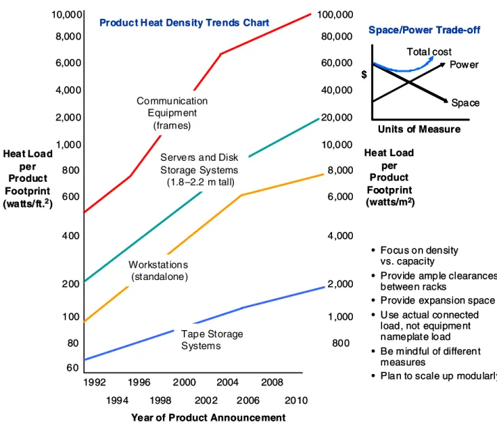
equipment (such as blade servers). Sufficient capacity should be delivered relative to patch panels, conduits and intermediate distribution feeds. Special attention should be focused on equipment densities relative to initial and longer-term electrical power capacities. Electrical capacity ranging from 30 watts to 70 watts per square foot for computer equipment is typically required. However, additional power is required for air conditioning, humidification, lighting, and uninterruptible power supply (UPS) and transformer losses. This additional demand could add one to one-and-a-half times more wattage to the electrical load, depending on equipment spacing and air-handling efficiencies. In Figure 2, heat densities are expressed in watts per square foot for the equipment footprint. Actual watts per square foot over the raised floor would be substantially less when aisle space — and other space — is included in the calculation.
Publication Date: 22 April 2005/ID Number: G00127434 Page 6 of 26 © 2005 Gartner, Inc. and/or its Affiliates. All Rights Reserved.
Figure 2. The Density vs. Capacity Debate
Product H eat Density Trends Chart
Power Space Total cost $ Space/Power Trade-off • Focus on density vs. capacity
• Provide ample clearances between racks
• Provide expansion space • U se actual connected
load, not equipment nameplate load • Be mindful of different
measures
• Plan to scale up modularly Units of Measure Heat Load per Product Footprint (watts/m2) Heat Load per Product Footprint (watts/ft.2)
Year of Product Announcement 1992 1994 1996 1998 2000 2002 2004 2006 2008 2010 10,000 8,000 6,000 4,000 2,000 1,000 800 600 400 200 100 80 60 100,000 80,000 60,000 40,000 20,000 10,000 8,000 6,000 4,000 2,000 1,000 800 Tape Storage Systems Workstations (standalone)
Servers and Disk Storage Systems (1.8–2.2 m tall) Communication
Equipment (frames)
Product H eat Density Trends Chart
Power Space Total cost $ Space/Power Trade-off Power Space Total cost $ Space/Power Trade-off • Focus on density vs. capacity
• Provide ample clearances between racks
• Provide expansion space • U se actual connected
load, not equipment nameplate load • Be mindful of different
measures
• Plan to scale up modularly Units of Measure Heat Load per Product Footprint (watts/m2) Heat Load per Product Footprint (watts/ft.2)
Year of Product Announcement 1992 1994 1996 1998 2000 2002 2004 2006 2008 2010 10,000 8,000 6,000 4,000 2,000 1,000 800 600 400 200 100 80 60 100,000 80,000 60,000 40,000 20,000 10,000 8,000 6,000 4,000 2,000 1,000 800 Tape Storage Systems Workstations (standalone)
Servers and Disk Storage Systems (1.8–2.2 m tall) Communication
Equipment (frames)
Source: The Uptime Institute and the Thermal Management Consortium, a collaborative effort of Amdahl, Cisco Systems, Compaq Computer, Cray, Dell, EMC, Hewlett-Packard, IBM, Intel, Lucent Technologies, Motorola, Nokia, Nortel Networks, Sun Microsystems and Unisys
Gartner recommends that the data center be designed to scale from 50 watts to 100 watts per square foot for raised floor areas. Incremental capacity can be added on a modular basis. Action Item: Focus on density vs. capacity; consider more-liberal spacing between racks to mitigate heat gain by improving airflow.
1.2 Rack Layout
Tactical Guideline: Distribute high-density racks throughout the layout to mitigate hot spots; use spot cooling as necessary.
Modern blade servers can be packed into a single-rack enclosure, resulting in power demands of 18 to 20 kilowatts per rack. The primary issue with dense-packing the layout with high-capacity
Publication Date: 22 April 2005/ID Number: G00127434 Page 7 of 26 © 2005 Gartner, Inc. and/or its Affiliates. All Rights Reserved.
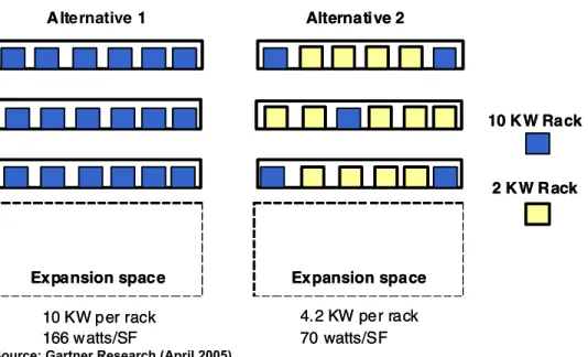
servers is that, although it is efficient from a space standpoint, it creates serious heat problems requiring incremental cooling, as well as significant incremental electrical costs (see Figure 3). Figure 3. Rack Layout Resulting Power Demands
A lternative 1 Alternative 2 10 K W Rack 2 K W R ack 10 KW per rack 166 w atts/SF 4.2 KW per rack 70 watts/SF
Expansion space Expansion space
A lternative 1 Alternative 2 10 K W Rack 2 K W R ack 10 KW per rack 166 w atts/SF 4.2 KW per rack 70 watts/SF
Expansion space Expansion space
Source: Gartner Research (April 2005)
Alternatives to a dense-pack approach would involve blending high and low density throughout the layout. In Alternative 1 in Figure 3, the racks are fully packed with high-density blade servers, which require 166 watts per square foot in electrical capacity. In Alternative 2, a blend of high- and low-density rack configuration results in 70 watts per square foot. This enables expansion of up to an additional 30 watts per square foot in the expansion space (assuming an optimal level of 100 watts per square foot). In Alternative 1, electrical demand is already exceeding this threshold, so that expansion would not be possible without adding additional electrical and cooling capacity. Action Item: Avoid dense-packing the racks with energy-intensive servers; combine high-density racks with lower-density racks to mitigate the heat effects of a high concentration of energy-intensive servers. If possible, trade space for density, since energy costs are typically four to five times the cost of space.
1.3 Rack Units
Tactical Guideline: Use a rack unit as the primary planning factor for estimating the space and power requirements of the data center. Each rack configuration should reflect total power, space and floor-loading demands. Strive for an average of 4 kilowatts per rack across the layout.
Traditionally, facilities planners used space-planning factors. such as square feet per rack or watts per square foot to estimate data center capacity. The problem with this approach is that it fails to capture the energy intensity associated with high-density rack configurations. An overall watts per square foot calculation fails to recognize the diversity from one rack configuration to the next, where significant hot spots can require incremental air-conditioning capacity. Gartner recommends planning the data center on a rack-unit basis (see Figure 4). This technique requires that each rack configuration be calculated from a total-wattage standpoint, in terms of equipment power and incremental power (that is, 60 percent) for air conditioning.
Publication Date: 22 April 2005/ID Number: G00127434 Page 8 of 26 © 2005 Gartner, Inc. and/or its Affiliates. All Rights Reserved.
Figure 4. Use Rack Unit — The Primary Planning Factor
Power per Rack Watts
Server blade enclosure 50
Patch panel power 25
Wattage per server 43
x 10 servers per enclosure 430 Total wattage per enclosure 505 x five enclosures per rack 2,525 Add energy factor for HVAC power (60 percent) 1,515
Total Wattage per Rack 4,040
Total Space and Power Over Raised Floor (Base Case) — 200 Racks Space 6,000 square feet (200 x 30 square feet)
Expansion space 6,000 square feet (double the rack footprint for growth capacity during a 10-year period)
Total space 12,000 square feet
Power 808,000 watts
Watts per SF 67 watts (Use a design envelope of between 50 watts and 100 watts per square foot.)
Example
Goal:
Maintain an average of 4 kilowatts per rack over the raised floor
Source: Gartner Research (April 2005)
By aggregating the total rack population, total kilowatts and space can both be calculated. In the example above, a simple rack configuration of 200 racks, each housing 10 servers, results in a total space requirement of 12,000 square feet and a total power requirement of 808 kilowatts or 67 watts per square foot, which is well within the 50 to 100 watts per square foot planning envelope. If the average power demand exceeds 4 kilowatts per rack, this suggests that rack configuration should be replanned, or that additional space should be factored into the layout to optimize overall cost efficiency.
Action Item: Use the rack unit as the principle planning factor for calculating overall space and power demands for the data center.
2.0 Design Criteria
Client Issue: What are the critical design considerations and best practices in the site selection and design of data center facilities?
The Uptime Institute has established four levels of fault tolerance for data centers (see Figure 5). Tier 1 is the lowest level, and Tier 4 is the highest, with complete multiple-path electrical
distribution, power generation and UPS systems. Tier 1 specifies annual outage of up to 28.8 hours; Tier 2 specifies 22 hours; Tier 3 specifies 1.6 hours and Tier 4 specifies only 0.4-hour of annual outage, or 99.995 percent availability. The tier level will drive the design specifications for the new data center. The higher the tier level, the higher the investment level for building
construction and environmental equipment. Tier level or fault tolerance will be determined by the criticality of data center operations. In the financial industry, high availability and fault tolerance (that is, typically Tier 3 and Tier 4) are required to support 24x7 financial transaction activities and funds exchanges. For other organizations (such as universities) a lower fault tolerance is
Publication Date: 22 April 2005/ID Number: G00127434 Page 9 of 26 © 2005 Gartner, Inc. and/or its Affiliates. All Rights Reserved.
Figure 5. Design Criteria: Scope and Redundancy
Tier 1: Single path for power and cooling distribution; no
redundant components — less than 28.8 hours downtime/year Tier 2: Single path for power and cooling distribution; redundant
components — less than 22.0 hours of downtime/year Tier 3: Multiple power and cooling distribution paths, but
only one path active; redundant components; concurrently maintainable — less than 1.6 hours of downtime/year
Tier 4: Multiple active power and cooling distribution paths; redundant components; fault tolerant — less than 0.4 hour of downtime/year Tier 1: Single path for power and cooling distribution; no
redundant components — less than 28.8 hours downtime/year Tier 2: Single path for power and cooling distribution; redundant
components — less than 22.0 hours of downtime/year Tier 3: Multiple power and cooling distribution paths, but
only one path active; redundant components; concurrently maintainable — less than 1.6 hours of downtime/year
Tier 4: Multiple active power and cooling distribution paths; redundant components; fault tolerant — less than 0.4 hour of downtime/year
Source: Uptime Institute
The Uptime Institute is a nonprofit organization that focuses on the issues of high availability in the data center. It has a membership of 68 corporations that exchange best practices in the area of high-performance data centers. The Uptime Institute's tier classification system has been adopted as an industry-accepted standard for defining levels of data center fault tolerance. The Uptime Institute cautions that a level of availability cannot be ensured by design specification alone. Most service interruptions occur due to human error. Thus, attention to recruiting, skill development, training and a positive work environment will contribute to zero-defect, high-availability operations.
Unit capital costs for Tier 2 and Tier 3 levels of infrastructure are included in Section 3.
Action Item: Assess the level of fault tolerance for design specifications. Combine building system capabilities with employee training to ensure the highest level of availability.
2.1 Critical Building Systems
Tactical Guideline: Design and implement the data center as an integrated system that optimizes electrical power, space allocation and mechanical systems.
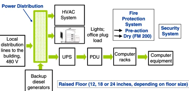
Five critical building systems require explicit engineering for a new or upgraded data center (see Figure 6).
• Power source — power distribution, including UPS, backup diesel generation, power distribution units (PDUs) and intermediate distribution units.
• Heating, ventilation and air conditioning (HVAC) systems — these may include rooftop units and distributed units that provide localized air cooling. Underfloor distribution of air can be an effective means of distributing air evenly throughout a raised floor area. Additional cooling and air handling may be required between racks. Perhaps the single greatest issue in the contemporary data center is maintaining adequate cooling and air movement, given the intense heat gain of modern blade server and direct-access storage device (DASD) equipment.
• Fire protection systems — including detection and abatement systems that most likely will combine pre-action wet systems interconnected with dry systems (such as FM 200 and Inergen) for sensitive areas, such as disk storage areas.
Publication Date: 22 April 2005/ID Number: G00127434 Page 10 of 26 © 2005 Gartner, Inc. and/or its Affiliates. All Rights Reserved.
• Raised floor systems — 12 inches for less than 1,000 square feet; 12 to 18 inches for 1,000 to 5,000 square feet; 18 to 24 inches for 5,000 to 10,000 square feet; and 24 inches for more than 10,000 square feet. Each of these systems will be addressed in the balance of this report.
Figure 6. Critical Building Systems
Fire Protection System Pre-action Dry (FM 200) Security System Power Distribution Local distribution lines to the building, 480 V HVAC System Lights; office plug load Backup diesel generators
UPS PDU Computer
racks equipmentComputer
Raised Floor (12, 18 or 24 inches, depending on floor size) Fire Protection System Pre-action Dry (FM 200) Security System Power Distribution Local distribution lines to the building, 480 V HVAC System Lights; office plug load Backup diesel generators
UPS PDU Computer
racks equipmentComputer
Raised Floor (12, 18 or 24 inches, depending on floor size) Source: Adapted from “Data center power requirements: measurements from Silicon Valley,” J. Mitchell Jackson, J.G. Koomey, B. Nordman and M. Blazek (July 2001: University of California, Berkeley)
2.2 Planning and Designing
Tactical Guideline: Ensure that IT representatives participate in the selection of the
architecture and engineering firm that will design and engineer the new data center. Focus particularly on the qualifications, experience and references of the architecture and engineering project leader.
Depending on the acquisition strategy of a new data center (that is, build, buy, lease or sublease), the level of improvements could vary from a complete building fit-out to minor modifications and enhancements (see Figure 7).The critical design considerations include a complete electrical power design, including power distribution — that is, main distribution frame (MDF) and
intermediate distribution frame (IDF) systems; UPS systems, diesel backup power systems and fire retardant systems (that is, wet and dry systems); security monitoring systems; and
mechanical systems (such as HVAC).
Pre-action wet systems are typically required by local fire codes. "Pre-action" means that the sprinkler pipes are charged with air, so that leaks or other faults are detected. The design will also develop a rack layout and determine the optimal electrical and air cooling distribution system, based on rack densities The space design will focus on the raised floor area, rack layout, workstations and support areas, such as conference and supply rooms, as well as shipping, receiving and staging areas.
Publication Date: 22 April 2005/ID Number: G00127434 Page 11 of 26 © 2005 Gartner, Inc. and/or its Affiliates. All Rights Reserved.
Figure 7. Engineering Plan and Space Design
Space Design • Raised floor area • Office area
• Ancillary equipment rooms • Conference rooms • Supply room • Communication room • Shipping/receiving/equipment staging Electrical • Diesel generator
• Fuel tank (size and location) • Uninterruptible power supply • PDUs (primary and secondary) • Electrical distribution (dual paths) • Building feeds, conduits, trenches • Watts/square foot
– Equipment footprint – Raised floor area – Total facility
Mechanical
• HVAC (tonnage, location and distribution)
• Cooling, heating, humidification • Filtering (particulate levels) Fire Protection
• Smoke detection • Pre-action wet systems • Dry systems Raised Floor • Height • Tile size Security System • Perimeter control • Access control • CATV • Biometrics • Centralized monitoring Floor Loading Fault Tolerance (Tier 1 to Tier 4) Communication
• Fiber entrance paths • Cable plant
CATV: community antenna television or cable TV HVAC: heating, ventilation and air conditioning PDU: power distribution units
Source: Gartner Research (April 2005)
Companies should provide surplus capacities in such core infrastructure as electrical and cable trenches, patch panels, conduits and spaces for additional PDUs. In addition, they should devise expansion plans for raised floor and support areas. This may take the form of expansion options if it is a leased facility, or other areas, such as storage, which can be used for expansion space. Action Item: Ensure that IT management participates in the selection of the architectural and engineering firm.
2.3 Location
Tactical Guideline: Develop a location decision process that identifies critical selection criteria, as well as assigns weights and scores to the criteria.
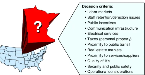
Data center location will affect operational and cost efficiencies significantly. In many cases, location criteria will be constrained by operational or technical requirements. For example, backup data centers that require synchronous replication will be limited to a radius of 30 to 50 miles from the primary data center. WAN costs may also limit the scope of the site search. However, many data centers can be located in distant locations. Thus, measures should be taken to optimize the location selection (see Figure 8). Critical factors include ample and reliable power and
communication infrastructures, favorable labor markets (that is, special attention may be required relative to staff retention and defection issues), and lower-cost real estate markets.
Publication Date: 22 April 2005/ID Number: G00127434 Page 12 of 26 © 2005 Gartner, Inc. and/or its Affiliates. All Rights Reserved.
Figure 8. Location Selection
Decision criteria: • Labor markets
• Staff retention/defection issues • Public incentives
• Communication infrastructure • Electrical services
• Taxes (personal property) • Proximity to public transit • Real estate markets
• Proximity to services/suppliers • Quality of life
• Security and public safety • Operational considerations
?
?
Source: Gartner Research (April 2005)
Many municipalities offer grants, tax abatements and other incentives to attract high-technology operations to their communities. IT management should also focus on operational issues, such as proximity to support services and public safety services, as well as the level of security in the target location.
Action Item: Develop location criteria and use a weighting method to score different locations against high-priority criteria.
2.4 Site
Tactical Guideline: Develop a comprehensive site selection checklist that stresses physical security and site flexibility, as well as sets priorities for adequate utilities, public services, and accessibility by employees and service providers.
The location of the data center will greatly affect security, operational efficiency and operating costs. Site criteria should include ensuring that there is reasonable commuting distance for employees, support vendors and other constituents; sufficient site area for parking, water and fuel storage; space for delivery truck access; and a location away from high-risk areas, such as airport-approach corridors, flood plains and areas that are prone to natural disasters, such as earthquakes, tornadoes or hurricanes. Avoid collocating near potentially hazardous areas, such as cafeterias, machine shops, wet labs or other facilities where fires or machine vibrations could present a hazard to data center operations.
Choose a site that is sufficiently removed from neighboring structures to enhance security. Good setback from main highways or access streets is preferred. If located in a multitenanted building, look to occupy the ends of the building to minimize disruptions from neighboring tenants. Ensure that the site is adequately serviced for all critical utilities, including power and water. The site plan should provide areas for building and parking lot expansion. Finally, ensure that local codes, building ordinances and zoning restrictions will not impede planned data center operations, such as the operation of diesel generators (see Figure 9).
Publication Date: 22 April 2005/ID Number: G00127434 Page 13 of 26 © 2005 Gartner, Inc. and/or its Affiliates. All Rights Reserved.
Figure 9. Site and Building Selection Criteria
Site/Location:
• Preferably not near residential or
other sound-sensitive users
• Maximum of one-hour distant commutation
from major end users
• Adequate site for at-grade development (for example, parking, water storage, fuel storage, transformer yard or substation or generators)
• Ready access to power from diverse sources
(such as multiple grids)
• Truck access for equipment delivery • Assess proximity to sources of vibration and
high-risk sources (such as airports and rail lines)
• Location outside flood plains and tornado- and hurricane-prone areas
• Local authorities amenable to building use
Site/Location: • -• -• -• • • high-• -• Site/Location:
• Preferably not near residential or
other sound-sensitive users
• Maximum of one-hour distant commutation
from major end users
• Adequate site for at-grade development (for example, parking, water storage, fuel storage, transformer yard or substation or generators)
• Ready access to power from diverse sources
(such as multiple grids)
• Truck access for equipment delivery • Assess proximity to sources of vibration and
high-risk sources (such as airports and rail lines)
• Location outside flood plains and tornado- and hurricane-prone areas
• Local authorities amenable to building use
Site/Location: • -• -• -• • • high-• -•
Source: Gartner Research (April 2005)
Action Item: Develop a comprehensive site selection checklist that stresses physical security and site flexibility, and sets priorities for adequate utilities, public services, and accessibility by employees and service providers.
2.5 Architecture
Strategic Imperative: Single-story, industrial-type buildings with large floor plates in suburban locations are the best sites for data centers.
In some cases, a facility with enhanced environmental improvements may be available for purchase or lease/sublease within a targeted market area. The building type can significantly affect occupancy costs, security, expansion and operational flexibility. As a general rule, avoid multistory office buildings with small floor plates. Opt for single-story, windowless structures, with large open floor plates (such as industrial structures). They offer lower rental and operating costs, better physical security and more-flexible space configuration. Consider building floor sizes with large column spacing — ideally 40 feet. Consider higher floor-to-floor clearances — 13 to 14 feet from structural slab to lowest structural member. Avoid above-grade location of the raised floor. If unavoidable, ensure that the building has adequate and multiple riser capacity for
primary/emergency power distribution, diverse fiber entries, and other vertical services.
Target buildings that have dual electrical grid service and dual communication connectivity. Avoid issues such as vibration and electromagnetic interference from power utility lines (see Figure 10). In terms of security, provide for multiple levels of secured access within the data center, and within specialized, highly secure areas within the data center (such as tape vaults) by using card key systems in combination with a biometric authentication system.
Publication Date: 22 April 2005/ID Number: G00127434 Page 14 of 26 © 2005 Gartner, Inc. and/or its Affiliates. All Rights Reserved.
Figure 10. Site and Building Selection Criteria (Continued)
Architectural:
• Larger column bays (30 feet x 50 feet is good) Minimum 13 ½ feet clear from structural slab to lowest structural member
• Efficient floor plates (that is, rectangular, square or side core preferable)
•
• Minimal fenestration; hardened facilities preferred
• Good roof —level roof without skylights
• Loading docks for equipment delivery access
• Compactor for rubbish removal
• Single point of entry and sufficient setback of building for perimeter security purposes
• Multiple story only: adequate riser space for primary/emergency power, HVAC, diverse fiber entries and other vertical services
• Rooftop acoustic and aesthetic screening for mechanical equipment
50,000 to 75,000 usable square feet preferable
•
Source: Gartner Research (April 2005)
Action Item: Ideally, select industrial-type, single-story buildings, with large bay sizes, high ceilings and a minimal number of windows.
2.6 Power Distribution
Tactical Guideline: Build additional capacity into the main electrical components, such as patch panels and conduits, and use higher-gauge electrical wire to accommodate future growth in electrical demand.
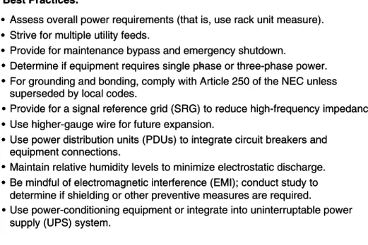
The electrical power plant and distribution system design is crucial to data center reliability and operational efficiency. As mentioned earlier, new blade server technology creates enormous power demands to energize the servers and to support incremental air-conditioning requirements. Several fundamental principles should serve as the foundation for the electrical system design (see Figure 11). These include the provision of maintenance and emergency shut down switches at all entry points in the facility, a grounding system that complies with the National Electrical Code, Article 250, or local codes if applicable; the provision of a signal reference grid (SRG) to reduce high-frequency impedance; the use of higher-gauge wire for future electrical expansion, the use of PDUs to integrate circuit breakers and equipment connections; and the use of power-conditioning equipment to integrate with the UPS. Consider using electrical-cable trays in the raised floor to separate signal cables from electrical cables, and to enhance the airflow throughout the raised floor.
Publication Date: 22 April 2005/ID Number: G00127434 Page 15 of 26 © 2005 Gartner, Inc. and/or its Affiliates. All Rights Reserved.
Figure 11. Power Distribution
Best Practices:
• Assess overall power requirements (that is, use rack unit measure). • Strive for multiple utility feeds.
• Provide for maintenance bypass and emergency shutdown.
• Determine if equipment requires single phase or three-phase power. -• For grounding and bonding, comply with Article 250 of the NEC unless
superseded by local codes.
• Provide for a signal reference grid (SRG) to reduce high-frequency impedance. •
• Use power distribution units (PDUs) to integrate circuit breakers and equipment connections.
• Maintain relative humidity levels to minimize electrostatic discharge. • Be mindful of electromagnetic interference (EMI); conduct study to
determine if shielding or other preventive measures are required. • Use power-conditioning equipment or integrate into uninterruptable power
supply (UPS) system.
Use higher-gauge wire for future expansion. Best Practices:
• Assess overall power requirements (that is, use rack unit measure). • Strive for multiple utility feeds.
• Provide for maintenance bypass and emergency shutdown.
• Determine if equipment requires single phase or three-phase power. -• For grounding and bonding, comply with Article 250 of the NEC unless
superseded by local codes.
• Provide for a signal reference grid (SRG) to reduce high-frequency impedance. •
• Use power distribution units (PDUs) to integrate circuit breakers and equipment connections.
• Maintain relative humidity levels to minimize electrostatic discharge. • Be mindful of electromagnetic interference (EMI); conduct study to
determine if shielding or other preventive measures are required. • Use power-conditioning equipment or integrate into uninterruptable power
supply (UPS) system.
Use higher-gauge wire for future expansion.
Source: Gartner Research (April 2005)
Action Item: Build additional capacity into the main electrical components (such as patch panels, conduits and higher-gauge electrical wire) to accommodate future growth in electrical demand.
2.7 Power Supply
Tactical Guideline: If possible, provide three lines of defense for backup power: multiple feeds from the public utility; UPS service to provide a minimum of 20 minutes of backup power; and, if necessary, diesel generators to sustain power for longer-term outages. The UPS — and, in many cases, the backup diesel-powered generators — are crucial to maintaining a constant flow of power in the event of a power failure from the public utility (see Figure 12). Several basic principles should guide the size and capability of the UPS system. First, the UPS should be sized to energize all computer equipment, HVAC systems and other electrical devices (such as emergency lighting and security devices) for 100 percent of the power demand for no less than 15 to 20 minutes after a power interruption. Second, the UPS should be sized for "peak" load or fault overload conditions. This relates to the surge in power demand when the equipment is first energized. As a rule of thumb, size the UPS for 150 percent of operating demand. Third, the UPS should be continuously operational to filter and condition the power.
Publication Date: 22 April 2005/ID Number: G00127434 Page 16 of 26 © 2005 Gartner, Inc. and/or its Affiliates. All Rights Reserved.
Figure 12. UPS/Backup Generators
Uninterruptible Power Supply (UPS):
• Sized to power 100 percent of the equipment until backup power kicks in.
• Also sized for "peak" load or fault overload conditions.
• Should be continually online to filter and condition power.
• If UPS is not used, then surge protection should be provided at the panels with a stand-alone
isolation/regulation transformer. Backup Generators:
• Needed to achieve Tier 3 and Tier 4 fault tolerance.
• Required if outages in excess of 20 minutes are anticipated.
• Consider local code compliance regarding fuel storage and noise abatement.
• Consider exhaust and vibration effects.
• Plan for maintenance and diesel fuel contracts.
• Plan for periodic test of the generators. Uninterruptible Power Supply (UPS):
• Sized to power 100 percent of the equipment until backup power kicks in.
• Also sized for "peak" load or fault overload conditions.
• Should be continually online to filter and condition power.
• If UPS is not used, then surge protection should be provided at the panels with a stand-alone
isolation/regulation transformer. Backup Generators:
• Needed to achieve Tier 3 and Tier 4 fault tolerance.
• Required if outages in excess of 20 minutes are anticipated.
• Consider local code compliance regarding fuel storage and noise abatement.
• Consider exhaust and vibration effects.
• Plan for maintenance and diesel fuel contracts.
• Plan for periodic test of the generators.
Source: Gartner Research (April 2005)
If a UPS is not used, then surge protection should be provided at the panels with a stand-alone isolation/regulation transformer. To sustain power beyond the 20-minute threshold, install a diesel generator to provide backup power for longer-term outages. For Tier 3 and Tier 4 levels of fault tolerance, an additional backup generator will be required. Consider local ordinances and codes relating to fuel tank location and noise abatement. Periodically test the generators to ensure their operational integrity.
Action Item: Specify the UPS and backup generator capacity to meet total peak load.
2.8 Mechanical Systems
Tactical Guideline: Strive for redundancy in the HVAC system by installing multiple units; focus on rack and tile placement to maximize the efficient flow of chilled air; use spot cooling as needed.
As discussed at the beginning of this research, cooling the data center has become a crucial issue relative to the incremental heat demands of modern high-density server technology (see Figure 13).
Publication Date: 22 April 2005/ID Number: G00127434 Page 17 of 26 © 2005 Gartner, Inc. and/or its Affiliates. All Rights Reserved.
Figure 13. Mechanical Systems
Return air plenum
HVAC Rack Rack Supply plenum Raised floor K ey Considerations: • Temperature —70 to 74 degrees F
• Relative humidity —45 percent to 50 percent
• Bottom-to-top airflow
• Avoid centralized systems —opt for distributed units
• Use cold aisle/hot aisle rack configuration
• Maintain static pressure at 5 percent above room pressure
• Avoid air leaks in raised floor
• Use spot cooling as needed
• Maintain vapor barrier in perimeter, doorways and subfloor area
Source: Gartner Research (April 2005)
When designing the HVAC system, follow these key guidelines: Ensure an ambient temperature between 70 and 74 degrees F; maintain a relative humidity of 45 percent to 50 percent, and strive for redundant systems by installing multiple HVAC units (as opposed to relying on a single centralized chiller). The other key consideration is designing the airflow to maximize the flow of chilled air across and through the equipment racks. This requires that chilled air flow from bottom to top and from front to back through the racks. Alternating aisles between cold-aisle and hot-aisle facilitates a more-efficient temperature control. Maintain a static pressure within the raised floor plenum of 5 percent greater than the data center raised-floor area. Selectively position perforated tiles in the raised floor to direct chilled air into the rack area. Be sure to seal all penetrations in the raised floor to maintain a constant static pressure. Establish a vapor barrier throughout the perimeter of the data center to minimize condensation. Use spot cooling or special rack enclosures for hot spots in the data center layout.
Action Item: Strive for redundancy in the HVAC system by installing multiple units; focus on rack and tile placement to maximize the efficient flow of chilled air; use spot cooling as needed.
2.9 Raised-Access Floor
Tactical Guideline: Specify a raised-access floor (RAF) height relative to the overall data center size; consider using cast aluminum floor tiles to ensure maximum floor loading capability.
There is a debate about whether raised floors are actually required for cable management and chilled air distribution (see Figure 14).
Publication Date: 22 April 2005/ID Number: G00127434 Page 18 of 26 © 2005 Gartner, Inc. and/or its Affiliates. All Rights Reserved.
Figure 14. Raised Floors
Raised-Floor Height Levels
Facilities w ith less than 1,000 sq. ft. 12-inch RAF height Facilities w ith 1,000 to 5,000 sq. ft. 12- to 18-inch RAF height Facilities w ith 5,000 to10,000 sq. ft. 18- to 24-inch RAF height Facilities w ith 10,000 sq. ft. 24-inch RAF height Advantages:
• Provides for superior chilled airflow distribution pattern (bottom to top) • Ease of electrical and signal circuit changes
• Easier to maintain separation of power circuits from signal cabling
• Life cycle costs compare favorably with vinyl chloride tile flooring: – Raised floor —$19.95 to 21.70 per sq. ft.
– VCT —$20.00 to 22.00 per sq. ft.
RAF: raised-acc ess floor
Source: Gartner Research (April 2005)
The alternative to raised floors would be using vinyl chloride anti-static tiles, which presume lower installation costs. Gartner research confirms that RAFs provide the most-efficient and cost-effective solution for managing electrical and signal cable management, as well as providing the most-efficient distribution of chilled air throughout the data center. The raised floor also provides a superior signal reference ground (SRG), whereby the reference grid is mechanically bonded to the access floor system. In terms of raised floor heights, Gartner recommends a 12-inch raised floor for smaller data centers (that is, 1,000 square feet or less). For larger centers of between 1,000 and 5,000 square feet, an 18-inch height is recommended. For centers greater than 5,000 square feet, a 24-inch height will be required. The raised floor provides an optimum plenum for chilled air for modern computer equipment that is typically designed for bottom-to-top airflow. In addition, the raised floor provides a more suitable environment for electrical and signal cable management. In terms of life cycle costs, the raised floor compares favorably with vinyl tile installation.
Action Item: Specify cast aluminum floor tiles to ensure maximum floor-loading capability.
2.10 Fire Detection and Suppression
Tactical Guideline: Install a comprehensive fire detection and suppression system including firewall installation, heat and smoke detectors, sprinkler systems (that is, typically required by local fire codes), chemical "clean agent" systems and manual systems.
Because of the significant risk of electrical fires in a data center, installing a comprehensive fire detection and suppression system is mission-critical for protecting life and property, as well as ensuring quick operational recovery (see Figure 15).
Publication Date: 22 April 2005/ID Number: G00127434 Page 19 of 26 © 2005 Gartner, Inc. and/or its Affiliates. All Rights Reserved.
Figure 15. Fire Detection and Suppression
Detection:
Both heat and smoke detection
Installed in accordance with NFPA 72E Installed below raised floors and other areas Suppression:
• Follow NFPA 75 standard firewalls
• Sprinkler systems — both flooded and pre-action
• Chemical systems: FM 200 Inergen
Ecaro-25(FE 25); Novec 1230
H alon 1301 (no longer recommended or in production)
• Manual systems
Manual pull stations Portable fire extinguishers
Location specifically designed in relation to airflow patterns
• • • • — — — — — — Detection:
Both heat and smoke detection
Installed in accordance with NFPA 72E Installed below raised floors and other areas Suppression:
• Follow NFPA 75 standard firewalls
• Sprinkler systems — both flooded and pre-action
• Chemical systems: FM 200 Inergen
Ecaro-25(FE 25); Novec 1230
H alon 1301 (no longer recommended or in production)
• Manual systems
Manual pull stations Portable fire extinguishers
Location specifically designed in relation to airflow patterns
• • • • — — — — — —
Source: Gartner Research (April 2005)
Detection devices should be installed beneath the raised floor, as well as throughout the data center facility, in accordance with regulation NFPA 72E. Detectors should include both heat- and smoke-sensing devices and be interconnected with the fire suppression system, local alarms, and local or central monitoring stations. The detectors should be positioned in relation to airflow patterns to ensure early detection of an imminent electrical fire. Fire suppression includes four categories:
• The installation of fire-rated walls in accordance with the NFPA 75 standard
• The installation of a sprinkler system — either a pre-action or flooded system
• The use of a chemical or "clean agent" suppression system as the first line of defense
• Manual systems, including manual pull stations and portable fire extinguishers that are positioned throughout the data center
In terms of the "clean agent" systems, there are several viable alternatives to consider. FM 200 and Inergen systems are the most-widely used replacements for the Halon 1301 agent, which has been rendered unsuitable for environmental reasons and has been discontinued in production. Other systems include Ecaro-25 (FE 25) and Novec 1230.
3.0 Data Center Construction Costs — Tier 2
Tactical Guideline: Complete a value engineering study of data center construction costs and associated life cycle costs. Focus particularly on diesel power, UPS and electrical system design.
Client Issue: What cost elements are associated with different levels of data center reliability and fault tolerance?
Publication Date: 22 April 2005/ID Number: G00127434 Page 20 of 26 © 2005 Gartner, Inc. and/or its Affiliates. All Rights Reserved.
Figure 16. Data Center Construction Costs —Tier 2
Cost Line Item % of Total
Total Average Cost Average Cost Per Sq. Ft. 6.6% 12.0% 21.6% 20.5% 1. Demolition 2. General construction 3. Access floor system 4. Ceiling systems 5. Wall finishes 6. Floor finishes 7. Structural steel 8. Fire protection system 9. Plumbing systems 10. Mechanical systems 11. Electrical systems
12. Monitoring and security systems 13. Critical support equipment 14. General conditions 15. General contractor fee 16. Permit
17. Premium time
18. Construction management fee 19. Design fee 20. Reimbursable expenses Total project $18,965 276,293 124,773 31,978 30,591 24,844 123,868 141,736 35,883 503,066 909,728 34,475 863,429 195,187 113,569 17,549 91,935 156,793 156,793 17,396 $4,202,665 100% $1.79 26.11 11.79 3.02 2.89 2.35 11.70 35.77 3.39 47.54 85.96 3.26 81.59 18.44 10.73 1.66 8.69 14.82 14.82 1.64 $397.11 Average data center cost: Tier 2 10,583 SF (raised floor) 13,029 SF (total facility) 11 facilities Uninterruptible power supply: diesel generator
Source: Technology Management Inc.
The cost data in Figure 16 includes projects that met a Tier 2 level of redundancy. These projects ranged from a low of 3,400 square feet of raised floor area to a high of 13,000 square feet. The projects were completed in the past three years in several U.S. cities, including Washington, DC; San Francisco; Los Angeles; San Diego; Chicago; New York; Boston; Houston; Dallas; Baltimore; and Philadelphia. TMI, the project management firm providing the data, reported that these projects were located in unimproved, typical single-story, industrial-type buildings. The buildings required extensive fit-out for data center operations. In addition to construction costs, there were costs associated with the acquisition and installation of building and environmental equipment (such as diesel generators and fire suppression systems). These costs do not include the capital investment in data processing, servers, communication equipment and other IT equipment that is associated with data center operations, although they include cabling costs. Overall construction costs averaged $397.11 per square foot of raised floor area. The largest cost elements relate to diesel backup and UPS installations (that is, 20.5 percent in Line No. 11) and electrical
distribution (that is, PDUs and intermediary distribution; 21.6 percent in Line No. 13).
3.1 Data Center Construction Costs — Tier 3
Tactical Guideline: Weigh the risk of downtime with higher levels of redundancy; ensure that the incremental capital cost with higher tier levels are more than offset by the cost of downtime.
Publication Date: 22 April 2005/ID Number: G00127434 Page 21 of 26 © 2005 Gartner, Inc. and/or its Affiliates. All Rights Reserved.
The second cost survey addressed Tier 3 data centers in six facilities located in Las Vegas, Nevada; Portland, Oregon; Newark, New Jersey; Rochester, New York; Austin, Texas; and Chicago. These projects ranged in size from a low of 16,000 square feet of raised floor area to a high of 66,000 square feet (see Figure 17).
Figure 17. Construction Costs — Tier 3
Average data center cost: Tier 3 31,727 (raised floor) 38,774 (total facility) Six facilities Average Uninterruptible power supply: diesel generator
Cost Line Item % of Total
Total Average Cost Average Cost Per Sq. Ft. 1. Demolition 2. General construction 3. Access floor system 4. Ceiling systems 5. Wall finishes 6. Floor finishes 7. Structural steel 8. Fire protection system 9. Plumbing systems 10. Mechanical systems 11. Electrical systems
12. Monitoring and security systems 13. Critical support equipment 14. General conditions 15. General contractor fee 16. Permit
17. Premium time
18. Construction management fee 19. Design fee 20. Reimbursable expenses Total Project $211,141 1,039,442 196,976 74,505 80,668 53,230 506,885 1,134,928 111,535 1,446,994 3,079,871 403,814 4,338,844 609,395 428,341 140,872 494,074 492,996 420,587 56,965 $15,247,936 7.0% 7.7% 9.8% 20.8% 29.4% 100% $6.65 32.76 6.21 2.35 2.54 1.68 15.98 35.77 3.52 45.61 97.07 12.73 136.76 19.21 13.50 4.44 15.57 15.54 13.26 1.80 $480.60 Average data center cost: Tier 3 31,727 (raised floor) 38,774 (total facility) Six facilities Average Uninterruptible power supply: diesel generator
Cost Line Item % of Total
Total Average Cost Average Cost Per Sq. Ft. 1. Demolition 2. General construction 3. Access floor system 4. Ceiling systems 5. Wall finishes 6. Floor finishes 7. Structural steel 8. Fire protection system 9. Plumbing systems 10. Mechanical systems 11. Electrical systems
12. Monitoring and security systems 13. Critical support equipment 14. General conditions 15. General contractor fee 16. Permit
17. Premium time
18. Construction management fee 19. Design fee 20. Reimbursable expenses Total Project $211,141 1,039,442 196,976 74,505 80,668 53,230 506,885 1,134,928 111,535 1,446,994 3,079,871 403,814 4,338,844 609,395 428,341 140,872 494,074 492,996 420,587 56,965 $15,247,936 7.0% 7.7% 9.8% 20.8% 29.4% 100% $6.65 32.76 6.21 2.35 2.54 1.68 15.98 35.77 3.52 45.61 97.07 12.73 136.76 19.21 13.50 4.44 15.57 15.54 13.26 1.80 $480.60 Source: Gartner Research (April 2005)
The survey revealed an average raised floor size of 31,727 square feet, with a total average facility size of 38,774 square feet. Overall construction costs averaged $480.60 of raised floor area. Differences in construction rates (such as costs for electrical and critical support equipment) can be explained primarily by the higher level of redundancy required (that is, $81.59 per square foot for Tier 2 vs. $136.76 for Tier 3). Tier 4 facilities require even greater levels of investment, because all systems are duplicated and can exceed $1,000 per square foot in certain markets. In both cases, general conditions that relate to site clean-up and other contractor
non-construction activities were essentially the same; whereas premium time that relates to overtime payroll was substantially higher in the Tier 3 case (that is, $8.69 for Tier 2 vs. $15.57 for Tier 3). This is attributable to the greater complexity of the mechanical/electrical installations and the larger average size of the Tier 3 projects, which also tend to incur more overtime to meet schedule constraints.
Publication Date: 22 April 2005/ID Number: G00127434 Page 22 of 26 © 2005 Gartner, Inc. and/or its Affiliates. All Rights Reserved.
Action Item: Weigh the risks of downtime with higher levels of redundancy; ensure that the incremental capital costs with higher tier levels are more than offset by the cost of downtime.
4.0 Data Center Facilities Management Options:
Three organizational models can be adopted to manage data center facilities. There is no single preferred option; selection of the model will depend on overall facilities management within the company, the degree of facilities management expertise within the IT organization and the philosophy on matrix organizational structures.
• Model 1:Assign data center facilities management responsibility to the corporate facilities organization. In this model, the IT organization is the "customer" to the facilities management organization. The IT organization specifies facilities requirements, service levels, and budget parameters and constraints. The corporate facilities organization typically assigns personnel to the data center and manages the day-to-day facilities operations, including critical building systems, maintenance, repair and the contracting for specialized services, including physical security, cleaning, grounds maintenance, shipping and receiving. The benefit of this structure is that it leverages the professional expertise of the corporate facilities staff and ensures close alignment on facilities standards and policies.
• Model 2: The management of data center facilities is an IT organizational responsibility. In this model, facilities professionals report to the data center operations manager and manage the day-to-day facilities management tasks. In most cases, the IT facilities personnel will work closely with corporate facilities and coordinate on issues of facilities standards, security standards, environmental health and safety standards, and other corporate policies and guidelines. The IT facilities staff will also seek specialized services from the corporate facilities staff relating to site selection for new data centers, building construction or leasing, as well as specialized engineering services relating to electrical and mechanical systems design and engineering. This model ensures maximum control of the IT organization for its data center facilities operations.
• Model 3. This is a matrix model in which the IT facilities staff reports to the IT
organization, as well as to the corporate facilities organization. In the matrix structure, the IT facilities staff is accountable to the IT organization, relative to service
performance, infrastructure availability and efficiency, and facilities budget management. The IT facilities organization is accountable to the corporate facilities organization relative to individual employee performance, career development, training, and maintaining adherence to corporate facilities standards and policies. The matrix structure captures the benefits of the first two models, but, as with any matrix structure, it introduces the potential for organizational conflict over resource allocation and operational priorities, as well as disputes over facilities investment and levels of redundancy.
Communication: In all cases, it is a best practice to maintain close ties between the IT organization and the corporate facilities organization. This will require periodic joint staff
meetings, project review meetings and multidisciplined project teams, particularly for data center relocation or expansion projects. It is particularly important that facilities professionals work closely with IT procurement specialists in reviewing vendor product specifications relating to power requirements, redundancy features, floor loading factors, and issues relating to space and cooling. With the advent of high-density servers, problems with heat and power demand can wreak havoc with facilities power and cooling systems.
Publication Date: 22 April 2005/ID Number: G00127434 Page 23 of 26 © 2005 Gartner, Inc. and/or its Affiliates. All Rights Reserved.
5.0 Conclusion
Data center facilities rarely meet the operational and capacity requirements of their initial design. The combination of new technologies, such as blade servers, which require substantial
incremental power and cooling capacity; pressures to consolidate multiple data centers into fewer locations; the need for incremental space; changes in operational procedures; and potential changes in safety and security regulations converge to impose constant facilities changes in the modern data center. Thus, the overarching rule in data center facilities is to design for flexibility and scalability.
To accomplish this, Gartner offers the following recommendations:
• Use the rack unit as the basis for estimating power and space requirements.
• Avoid densely packing the racks, trade space for density and use spot cooling for hot spots.
• Take a comprehensive view of location and site selection — consider utility
infrastructure, labor and real estate markets, as well as public incentives, in the decision criteria.
• Opt for single-story, industrial-type buildings.
• Evaluate the level of redundancy (tier level) and its cost with the cost of downtime.
• Adopt the facilities organization model that best aligns with corporate culture and operational priorities. In all cases, maintain close communication and liaison between the facilities organization and the IT organization.
Appendix A. Conference Poll Results
Shown below are the results of four surveys that were conducted at Gartner’s Data Center Conference in December 2004 (see Figure 18, Figure 19 and Figure 20). This represents approximately 200 attendees in the facilities presentation. The survey results provide some insight into client experiences relative to facilities problems, tier levels and the power rating of the data center:
• Not surprisingly, more than 80 percent of the attendees identified heat, power and space issues as their most-important facilities-related issues.
• Thirty percent of the attendees reported that their data centers were designed to a Tier 4 level. Gartner research suggests that roughly 10 percent of U.S. data centers are designed to the Tier 4 level. This disparity might be explained by the fact that Data Center Conference attendees represent high-performance data centers and were, in some respects, self-selecting for the facilities presentation.
• In terms of power level, those attendees who knew their rating reported levels below 80 watts per square foot. Surprisingly, more than half of the attendees did not know the power ratings of their data centers.
Publication Date: 22 April 2005/ID Number: G00127434 Page 24 of 26 © 2005 Gartner, Inc. and/or its Affiliates. All Rights Reserved.
Figure 18. Conference Poll Results: Facility Problems
What is the greatest facility problem with your primary data center?
Excessive heat Insufficient raised floor area Insufficient power Poor location Excessive facility cost N one of the above 29% 21% 29% 6% 3% 13% Total: 112
What is the greatest facility problem with your primary data center?
Excessive heat Insufficient raised floor area Insufficient power Poor location Excessive facility cost N one of the above 29% 21% 29% 6% 3% 13% Excessive heat Insufficient raised floor area Insufficient power Poor location Excessive facility cost N one of the above 29% 21% 29% 6% 3% 13% Total: 112 Source: Gartner Research (April 2005)
Figure 19. Conference Poll Results: Tier Levels
What is the power rating of your primary data center?
<20 watts/ sq. ft. 20–59 watts/ sq. ft. 60–80 watts/ sq. ft. >80 watts/ sq. ft. Don’t know 3% 21% 10% 10% 57% Total: 104
What is the power rating of your primary data center?
<20 watts/ sq. ft. 20–59 watts/ sq. ft. 60–80 watts/ sq. ft. >80 watts/ sq. ft. Don’t know 3% 21% 10% 10% 57% Total: 104 Source: Gartner Research (April 2005)
Publication Date: 22 April 2005/ID Number: G00127434 Page 25 of 26 © 2005 Gartner, Inc. and/or its Affiliates. All Rights Reserved.
Figure 20. Conference Poll Results: Power Rating
To what “tier level” is your primary data center designed?
Don’t know 10% 28% 29% 30% 4% Tier No. 1 Tier No. 2 Tier No. 3 Tier No. 4 Total: 108
To what “tier level” is your primary data center designed?
Don’t know 10% 28% 29% 30% 4% Tier No. 1 Tier No. 2 Tier No. 3 Tier No. 4 Total: 108
Source: Gartner Research (April 2005)
Appendix B. Acronym Key
CATV community access television
DASD direct-access storage device
HVAC heating, ventilation and air conditioning
IDF intermediate distribution frame
MDF main distribution frame
PDU power distribution units
RAF raised-access floor
SRG signal reference grid