talento dialog
Switching programs
compiling editing transferring WA-Ekf 3893/06.99/S:MMS/D:Kohl/80.10.0938.7Contents
Before starting . . . .2 Installation/Deinstallation . . . .4 Introduction . . . 7 1. Switching programs . . . .8 2. Switching commands . . . .123. Compiling switching programs . . . .14
3.1 Program start . . . 16
3.2 Preparing switching programs . . . 16
3.3 Compiling week programs . . . 23
3.4 Compiling week programs with date assignments . . . 30
3.4.1 Week programs with date assignment without year number 30 3.4.2 Week programs with date assignment with year number . . 33
3.4.3 Week program with automatic date assignment . . . 35
I
3.5 Pulse switching command . . . 383.6 Cycle switching command . . . 39
3.7 Copying a part-program . . . 42 3.8 Deleting . . . 43 3.9 Advanced . . . 44 4. Graphic representation . . . .46 4.1 Graphic year . . . 46 4.2 Graphic, day(s) . . . 48
5. Evaluating a switching program . . . .50
6. Printing . . . .52
7. Code word . . . .54
8. Transferring a switching program . . . .56
9. Converting a switching program . . . .68
10. Options . . . .70
Before starting
Familiarity with the PC and practical experience with Windows are required for successfull work with “talento dialog“.
You are familiar with the following work steps: • Creating a file
• Saving a file • Printing a file
Installation/Deinstallation
Software requirements
This program works under the following operating systems: • Windows 3.x
• Windows 95 • Windows NT 4.0
Hardware requirements
PC-Hardware:
• 486 DX2 66, Pentium, Pentium-MMX or Pentium II • 4 MB RAM (8 MB recommended) for Windows 3.x • 8 MB RAM (16 MB recommended) for Windows 95 • 24 MB RAM (32 MB recommended) for Windows NT • 4 MB free hard disk memory for installing
the program files
External Hardware:
(Digital time switches and accessories):
• Year time switch (talento 891 ... 894; 991 ... 994) • talento taxxi = Manual programming unit
• Serial cable for connection to the PC (Standard 1:1 cable, included in the scope of delivery of the talento taxxi-set)
Intalling the Software
This program installs a Borland data base engine into the directory c:\idapi.
If this already exists, the necessary adaptations are to made during installation. The program is installed in the standard directory c:\talento\.
All details in this manual refer to this directory.
No conflicts with other applications are currently known when operating “talento dialog“.
• Insert the data carrier into the appropriate drive. • Select the language
• Select Run ... in the File menu (Windows 3.x).
or
• Select Run... in the start menu of Windows 95/NT.
• Start installation with Setup.exe and follow the instructions.
• If the installation has been completely carried out, you can start the program.
Mark the options:
Yes I want to restart the program.
Deinstalling software
During the installation, the logic operation “Deinstall“ was created in the target program group.
Note: Do notdelete the Borland database engine
(c:\idapi) manually, as the data base can also be used by other user programs. Only if you are absolutely sure that no other application accesses this data base, the directory and entries in the file win.ini can be deleted.
(Also see the Install.log file in the installation directory).
• Windows 3.x:
Start deinstallation in the talento program group. or
• Windows 95/NT:
Select – Deinstall – in the start menu – program group – talento.
Introduction
With “talento dialog“, compile the switching programs for digital time switches of the type:
• talento 891, 1-channel • talento 991, 1-channel
• talento 892, 2-channel • talento 992, 2-channel
• talento 893, 3-channel • talento 993, 3-channel
• talento 894, 4-channel • talento 994, 4-channel
without radio interface with radio interface
DCF77 DCF77
Every switching output of a time switch can control one load (application).
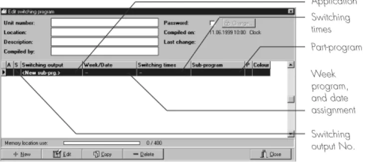
All time switches have 400 memory locations. In the Edit switching program window, the occupied memory locations are displayed, e.g. 53/400, indicated green. However, in the “talento dialog“you can create more part-programs (memory locations), indicated red, if you deactivate one ore more part-programs, see Section 3.3.4.
• Switching programs can be created in two different ways:
Under User support, select, See section 10 :
– Beginners
When compiling the switching programs, an assistant supports you during the individual program steps.
– Advanced
You should already be familiar with the programming steps.
The respective windows for entering the data are called up directly, see Section 3.9.
• The switching programs of the individual switching outputs are shown in clear tables or graphics: – Graphic, year
– Graphic, day(s)
• You can represent the switching programs as an evaluation:
– Switching times – Energy consumption
• You can protect the switching programs with a code word.
Figure 02: Contents of a part-program
1. Switching programs
Depending on the type of time switch, one to four applications are assigned to a switching program. • Yard lighting
• Sales lighting • Advertising lighting etc.
One ore more part-programs form an application. These consist of:
• Date
• Switching times • Switching commands
There are four different types of programs:
1.1 weekly program (without date assignment)
1.2 weekly program with data assignment
(From – to, without year number)
1.3 weekly program with date assignment
(from – to, with year number)
1.4 weekly program with automatic date assignment
Application Switching times Part-program Week program, and date assignment Switching output No.
1.1 Week program
A week programis a part-program without date assignment.
A number – e.g. 1 – is automatically assigned to this part-program.
You define which application is switched on at which days of the week.
Examples: • Every Monday
• Every Wednesday and Thursday • Every working day (Monday – Friday) • Every weekend
etc.
Switching ON and switching OFF of the applications can be programmed at different times for every day of the week.
Weekly programs always have the priority 0, (See Section 3.3.4 for Priority).
Only the priority 1-9 can be assigned to a part-program with date assignment.
1.2 Week program with date assignment,
without year number
Standard setting: A complete date with year number, the year number mustbe deselected. If a date range is assigned to a part-program, e. g. 24.12. to 26.12, all switching times in this part-program are executed in this period every year.
This part-program has a higher priority than a week program. However, it can be changed, See Section 3.3.4.
1.4 Week program with automatic
date assignment
Date assignments can also be automatically allocated to a part-program. There are two selection possibilities.
You can define these date assignments withor without a year number.
The corresponding switching times are executed in the usual way in the selected periods.
This part-program has a higher priority than a week program, but it can be changed, see Section 3.3.4.
Note: You assign a date to an existing
week program with the switching times No. 1.
The name date assignment No. 1: is allocated to this date assignment. When you create a new part-program, proceed as described in Section 3.3.
1.3 Week program with date assignment,
with year number
Standard setting: A complete date with year number. The year number is maintained. If a date range is assigned to a part-program, e. g. from 24.12.2000 to 26.12.2000, all switching times in this part-program are executed only once in this period.
This part-program has a higher priority than a week program and a program with date assignment without year number.
The new part-program, a new date assignment and new switching times automatically receive a name with ascending numbers,
e.g. for switching output 2: Date assignment No. 2 Switching times No. 2 Part-program No. 2 e.g. for switching output 3: Date assignment No. 3 Switching times No. 3 Part-program No. 3
The date assignments and switching times created in this way can be allocated as required to a new part-program. e.g. for switching output 4: Date assignment No. 2 Switching times No. 1 Part-program No. 3
2. Switching commands
Three types are available for switching the applications:
2.1 ON/OFF (Standard)
An ON/OFF switching commandis always
assigned to a switching time. A load is switched ON or OFF.
The state of the load is maintained until the next switching command.
2.2 Pulse (switching command with a defined
length for the ON or OFF state)
A pulse switching command is always assigned to a switching time.
The corresponding switching output is active for the defined pulse time.
A pulse switching command consists of: Start time
2.3 Cycle (cyclical switching command with
a defined length for the ON and OFF
state)
A cycle switching command is always assigned to a switching time.
The corresponding switching output is active/ inactive for the defined times.
A cycle switching command consists of: Start time
Cycle time (pulse time + pause) Pulse time
Note: Certain time switches of the “talento“ series are suitable for accurate-to-the-second switching (ON and OFF).
If you program switching commands in the second range, the following secondary effects can occur:
a) impaired lighting unit quality (flicker)
b) impaired radio reception (crackling) To prevent this, ensure that:
a) a maximum of one switching operation occurs per minute, under rated load or
one switching operation occurs per second, at maximum 0,28 x rated load
b) a maximum of five switching operations occur per minute and
there is more than one second
pause between two switching operations In each individual case, determine whether additional protective measures are necessary, e.g. installing appropriate components (varistor, suppresser diode, RC element)
3. Compiling switching programs
Familiarise yourself with the following sections.
On the basis of an example, you learn how a switching program is compiled. This was stored in your directory during installation on your hard disk (demo.tpx).
3.1 Program start
You learn how “talento dialog“is started.
3.2 Preparing a switching program
You learn how to select a time switch with the assistant and how to prepare its applications.
3.3 Compiling a week program
You learn how to compile a weekly program with the assistant.
3.4 Week program with date assignment
The assistant shows you:
3.4.1 How to assign a date/date range without year number to a week program.
3.4.2 How to assign a date/date range withyear number to a week program.
3.4.3 How to assign automatically a date/ date range with/without year number to a week program.
3.5 Pulse switching commands
You compile switching times with a pulse function.
3.6 Cycle switching commands
3.7 Copying part-programs
You learn how to copy and individually edit a part-program.
3.8 Deleting
You delete/remove entire part-programs and individual contents.
3.9 Advanced
When you are familiar with “talento dialog“, select the advanced user support, see Section 10.
3.1
Program start
You start “talento dialog“
• under Windows 3.x by double-clicking on the talentosymbol in the correponding program group.
• under Windows 95/NT via Start ➔Programs ➔
talento dialog
The Intro “talento dialog“window is open.
3.2 Preparing a switching program
3.2.1 Select application
You define for which time switch type the switching program is created. Click on the Select application button, or
In the menu File ➔ New... .
A new switching program is created and the Application assistantwindow is opened.
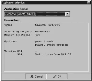
Figure 03: Select application
Figure 04: Application Assistant
Button Select application
Click on Select application... . The window Select application is opened.
Define the time switch type for which the switching program is to be created.
1-channel talento 891/991 or 2-channel talento 892/992 or
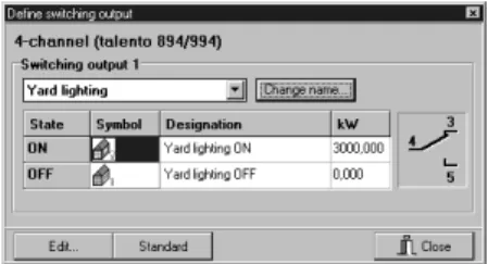
3-channel talento 893/993 or 4-channel talento 894/994 Example: 4-channel (talento 894/994)
Select application, close with OK.
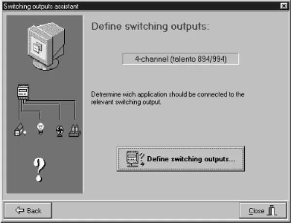
Click on Continue in the assistant. The Define switching outputs window is opened.
3.2.2 Defining application
You determine the basic settings for each application:
• Define the switching output • Select the switching symbol • Define designation
• Enter power rating
3.2.2.1 Defining switching output
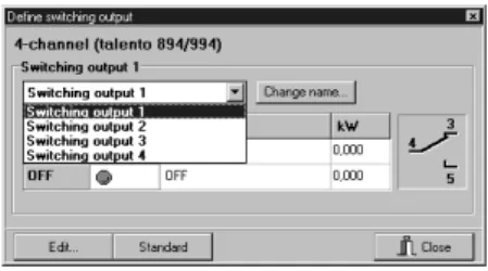
Click on the corresponding symbol. The Define switching output window is opened.
In the pulldown menu Switching output, select a switching output.
Example: Switching output 1 If necessary, you change the term “Switching output 1“. Click on
Change name… and enter a name which
describes the corresponding applications. Examples:
For switching output 1 = Yard lighting For switching output 2 = Sales room lighting For switching output 3 = Advertising lighting For switching output 4 = Heating, circulating air Confirm this entry with OK.
Figure 07: Define switching output
3.2.2.2 Selecting switching symbols
Click on the corresponding symbol and then on Edit….
This gives you a list for various applications with different symbols.
You determine the symbol for the relevant state – ON and OFF.
Example:
Select the application Yard lighting in the lighting for category
Building lighting ONfor switching ON Building lighting OFF for switching OFF Confirm this entry with OK.
Figure 09: Switching state symbol
3.2.2.3 Defining designation
Mark the table fields under Designation and click on Edit….
You can change the entry as required. Confirm this entry with OK.
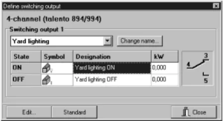
3.2.2.4 Entering power rating
Mark the table fields under kW and click on Edit….
Enter the power rating (rated capacity) of the connected load.
This value is the basis for calculating the energy consumption, see Section 5, Evaluate switching program.
Confirm this entry with OK.
Close Define switching output. Figure 11: Define the designation
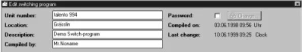
3.2.3 Project-specific information
Enter your individual data in these four fields:
• Unit number: e.g. Designation/
Time switch number
• Location: e.g. Storey/Number of
the distribution cabinet
• Description: e.g. Task of the switching
program
• Compiled by: e.g. Name of the
programmer Activate code word, see Section 7 Figure 13: Project-specific information
3.3 Compiling a week program
3.3.1 Defining the program
The yard lighting should be switched ON and OFF automatically:
Monday to Friday
05:30 ON 08:00 OFF
17:30 ON 21:30 OFF
Saturday
05:30 ON 08:00 OFF
The yard lighting remains OFF on Sundays.
Note: If you have set Beginner
under User support, see section 10,
you are supported by an assistant when entering the data.
3.3.2 Defining a switching output
With New, open the first window in the assistant.
Select the corresponding switching output. With Continue, open the second window in the assistant.
Note:
No date is assigned to a week program.
With Continue, open the third window in the assistant.
Figure 15: Assistant – 1. Switching output
3.3.3 Defining switching times Select Addor an existing entry and Edit. The Edit switching times window is opened.
Click on the clock symbol for switching time.
The Change timewindow is opened.
Set the appropriate times from the above examples.
The input is made as follows:
• Click on the field and enter the values or
• Click on the arrows next to the relevant input field, or
• Move the small clock pointer with the mouse
Example: Time: 5:30 Confirm this input with OK.
• You determine the days of the week on which the switching commands should be executed.
You can select days of the week individually or can combine any days of the week as a group.
Mark the individual fields
Mo - Tu - etc. or click on the bar under the days of the week.
Mo - Tu - We - Th - Fr or Sa - Su
In our example, the lighting remains OFF on Sundays.
Figure 19: Changing the time
• For our example, select the standard setting: ON/OFF under Type.
• Determine the switching state ON or OFF for Switching outputs (pulldown menu). • If required, you can make your individual
entries in the Designation fields:
e.g.: Yard lighting ON/yard lighting OFF. Confirm these inputs with OK.
The “talento dialog“ returns to the assistant.
A name has automatically been assigned to this switching time.
However, you can redefine this name – switching times No. 1– as required via Name. Under this name, you can define additional switching times (see example) in the usual way. Open the fourth window in the assistant with Continue.
Figure 18_02: Selecting type
3.3.4 Additional information
You can adapt these items to your individual requirements.
a) Give this part-program a designation e.g. routine program
b) Select a colour for this part-program. Choose another colour if necessary. The colour distinguishes another individual part-program in the graphic representation for the year overview.
c) You can change the defined priority (1-9). 0 = Week program only
1 = Low priority 9 = Highest priority
d) Determine whether this part-program should be active.
Example: You compiled several part-programs in advance and, at a given time, you determine which of them are used. The assistant is closed with End.
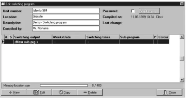
The new part-program – week program – is now listed in the Edit switching program window.
To print this representation: See Section 6. Figure 22: Yard lighting week program
Example: The defined week program should only be executed at certain times,
From 15.7. to 31.8. (Company holidays) From 10.9. to 30.9. (Autum holidays) etc.
The week program previously entered is listed in the Edit switching program. Mark your part-program.
Enter the second window in the assistant in the usual way.
3.4 Compiling a week program with
date assignment
3.4.1 Week program with date assignment, without year number
Standard setting: A complete date with the year number.
The year number mustbe deselected. If a date range is assigned to a part-program, e. g.:
From 15.7. to 31.8, all switching times in this part-program are executed every year during this period.
Open the Edit datewindow with Add. The current date (PC-date) is displayed.
• Under designation, enter a name which describes the relevant date range, e.g. summer holidays.
• By clicking with the mouse next to the number fields, open another input field. Enter the corresponding details From: to:
In the case of an individual date, the same date is in both fields. • The year number mustbe deselected.
All switching times in this part-program are executed every yearduring this period. Confirm this input with OK.
Figure 23: Edit date
A name is automatically assigned to this date range/individual date.
However, you can redefine this name – date assignment No.:1– via Change name. With Add,enter all data in turn which belongs to this part-program.
All further steps are identical, whereby you can immediately determine the switching times after defining the switching output – if necessary.
With Continue, open the third window in the assistant, see Section 3.3.3
3.4.2 Week program with date assignment, withyear number
Standard setting: A complete date with year number.
The year number is maintained.
If a date range is assigned to a part-program, e. g. from 24.12.2000 to
26.12.2000, all switching times in this part-program are executed only oncein this period.
The previously entered week program is listed in the Edit switching programwindow. Mark your part-program.
Enter the second window in the assistant in the usual way.
With Add, open the Edit datewindow. The current date (PC date) is displayed. Figure 25: Edit date
A name has been automatically assigned to this range/single date.
However, you can redefine this name – date assignment No. 1 – via Change name . With Add, add in turn all data which belong to this part-program. All further steps are identical, whereby you can immediately define the switching times after defining the switching output – if required.
Continuewith the third window in the Assistant, see Section 3.3.3
• Under Designation, enter a name which describes the relevant date range, e.g. Christmas.
• By clicking on the mouse next to the numbers field, open another input field. Give the corresponding information From: to:
In the case of a single date, the same date is in both fields.
• The year number is maintained. All switching times in this part-program are executed only once in this period. Confirm this input with OK.
3.4.3 Weekly program with automatic date assignment
You can automatically assign date ranges to any part-program.
The previously entered weekly programis listed in the Edit switching program window. Mark your part-program.
Enter the second window in the assistant in the usual way.
With Add, open the Edit datewindow. With Auto, open the Automatic add window. You can choose from the two possibilities: • Public holidays
Choose your country.
An overview of the usual public holidays for that country is listed.
In the relevant line, double click to define which public holidays remain active and which do not.
Other selection criteria are:
• All • Floating • Defaults
• None • Fixed
Confirm your selection with OK.
Note: Your details are now listed in the switching program assistant. You can mark a particular line and hide/ deselect the year numbers for these details via Editin the window Edit date.
The assigned switching times are executed accordingly, see Sections 3.4.1 and 3.4.2.
With Continue, open the window 3. Switching times, see Section 3.3.3 With Continue, open the window 4. Miscellaneous, see Section 3.3.4 Figure 27: Public holidays selection
Selection on the basis of months:
By clicking with the mouse, you determine whether the first of the relevant month remains active or not.
Other selection criteria are:
• All • Even • 1st half year
• keine • ungerade • 2ndhalf year
Confirm your selection with OK.
Note: Your details are listed in the switching program. You can mark a particular time and hide/deselect the year number for the details in the window Edit date.
The assigned switching times are executed accordingly, see Sections 3.4.1 and 3.4.2.
With Continue, open the window 3. Switching times, see Section 3.3.3 With Continue, open the window 4. Miscellaneous, see Section 3.3.4 Figure 28: Months selection
3.5 Pulse switching command
An application is to be switched ON at a certain time and switched OFF after a predefined time.
A pulse switching commandconsists of: Start time
Pulse time (ON or OFF) Example:
Start time Monday to Friday 08:00
Pulse time 10 Seconds
Enter and input the data with the assistant, see Section 3.3 and 3.4
• Start time • Weekday(s) • Switching state
• Under Designation, enter a name which describes the relevant application, e.g. Spotlight
• Type/pulse
You obtain an additional input field for the pulse time/Unit of measurement.
Pulse time: 1 to 99 seconds or 1 to 99 min. Confirm these inputs with OK.
The “talento dialog“ returns to the assistant. Figure 29: Pulse switching command
Pulse time
3
2ndexample:
Start time Montday to Friday 09:00
Cycle time 60 Minutes
Pulse time 10 Minutes
Option:
End time Montday to Friday 19:00
3.6 Cycle switching command
An application is switched ON at a particular time. However, it should switch ON and OFF
automatically in a predefined cycle. A cycle switching commandconsists of: Start time
Cycle time (pulse time + pause) Pulse time
If you assign no end time to a cycle switching command, it operates continuously.
In practice, an end time is mostly a standard OFF switching command.
However, an end time mustbe a standard ON switching command if your application should be switched ON at the end of the cycle.
1st example:
Start time Monday 08:00
Cycle time 60 Minutes
Pulse time 10 Minutes
Option:
End time Friday 19:00
Pulse time
Start time End time
Cycle time Pause
Entry and input of the data performed with the assistant, see Section 3.3 and 3.4
Define: • Start time • Week day(s) • Switching state
• Under Designation, enter a name which describes the relevant application, e.g. Spotlight
• Type/cycle
The switching state is set to ON and you open the window Program cycleand click on the clock symbol under cycle.
Figure 30: Cycle switching command
Open window Program cycle
Supplement your inputs:
• Cycle time: 1 to 99 sec. or 1 to 99 min • Pulse time: 1 to 99 sec. or 1 to 99 min
(ON switching duration)
Note: The pulse time can never be set longer
than cycle time. If you attempt to set a pulse time which is longer than the cycle time, this value is automatically
increased by one.
The previously set start time can be changed in this window if required.
Confirm these inputs with OK.
The “talento dialog“ returns to the assistant. Figure 31: Program cycle
3.7 Copying a part-program
You can copy existing part-programs.
In the copy, you change only the data which must be adapted for your “new“ part-program.
In the Edit switching program window, mark the corresponding part-program, e.g. switching output 1, week program 1, switching times No. 1, part-program No 1.
With Copy, open a window and there define the required switching output for your „new“ part-program.
Confirm your selection with OK.
The copied part-program is now also listed in the window Edit switching program,but with a new name, e. g. switching output 2, week programs, Switching times No. 2, part program 2
All data in the “new“ part-program is – as described in Section 3.3 – adapted accordingly to suit the current requirements.
Figure 32: Copying part-program
3.8 Deleting
All data which was entered can be deleted in the relevant window.
You delete/remove the active line in each case. • In the window Edit switching program
a complete part-program (e.g.: part-program No. 1)
• In the relevant window in the assistant:
– 2. Date assignment –
the selected date
– 3. switching times – the selected switching times
• In the window Overview part-program (user support, advanced)
– The selected date/date range
3.9 Advanced
If you have set “Advanced“ under user support, see Section 10, the window Overview
part-program is opened when a new program
is complied or when an existing one is edited. When the individual data items are entered, the same windows are opened which you already know from the assistant.
Figure 35: Start year graphic
Figure 36: Graphic year
4. Graphic representation
4.1 Graphic year
This graphic gives an overview of the year, which you defined. You recognize the active part-programs by the colour assignment.
4.1.1 Enter via: • The key F5
• The main menu Edit➔ Graphic year • Click on the button Graphic year The graphic is opened and recalculated at the same time (see options, settings).
4.1.2 Defining the year for the representation: • The left and right arrow keys,
by 1 year in each case
• By clicking with the mouse next to the numbers field you open another input
Button Graphic year
Define the year number
4.1.3 Define the switching outputs: • All
• Individual
4.1.4 Recalculating/updating a Graphic • Only when the appropriate markings
is deactivated under Options/Settings. • Only when changes have been made in
the switching programs
Note: In this representation, double-clicking on any day opens the Day(s) graphic.
Figure 37: Start day Graphic
Figure 38: Graphic day(s)
4.2 Graphic day(s)
This graphic offers you a detailed overview of the active switching programs.
4.2.1 Enter via: • The key F6
• The main menu Edit➔ Graphic day(s) • Click on the button Graphic day(s) The graphic is opened and recalculated at the same time. (see Options, Settings)
4.2.2 Defining the date for the graphic start:
• With the left and right arrow keys, in each case. By the number of days set under Day(s). • By clicking with the mouse once next to the
numbers field, you open the input filed for the date.
4.2.3 Selecting the number of days to be shown: • 1 to 7 days Button Graphic day(s) Define the date Select the resolution Define the number of days
4.2.4 Define the resolution of the representation: • 1, 2, 3, 4, 5, 10, 15, 20 min
Note: In the case of switching operations which follow each other quickly, (e.g. 16:00 ON, 16:01 OFF) select a high resolution, e.g. 1 min.
4.2.5 Recalculating/upgrading a graphic • Only if the corresponding marking is
deactivated under Options/settings
• Only if changes have made in the switching program
Note: In this representation, the window Switching output infois opened by clicking once with the mouse at any point.
4.2.6 Switching output info
• Always refers to the last switching operation of the selected representation on this day, at the relevant time
• You can directly open the corresponding part-program for editing
Figure 39: Start Evaluation
Figure 40: Evaluation
5. Evaluating a switching program
The evaluation shows you: • The number of switching points
• The duration of ON and OFF switching states • The pulse times
• The cycle/pulse times
• The consumption in kWh – this information is only correct if it corresponds with the nominal data of the connected load.
5.1 Enter via:
• The key F7
• The main menu Edit➔ evaluate switching program
• Click on the
Evaluate switching program button
Evaluate switching program button Start evaluation from: Start evaluation until:
5.2 Defining the date and time
for the evaluation:
• Enter the input field for the date by clicking once with the mouse next to the numbers field. • With the clock symbol button, open the input
field for the time
5.3 Starting evaluation
• The evaluation can take some time, depending on the size of the program
6. Printing
The contents of the switching program can be printed for an item of documentation,
e.g. customer files.
6.1 Enter via:
• The main menu Print ➔ file
This gives you a preview in each case. The contents of the respective active window are printed.
• Edit switching programs
The switching program appears in list form. This can be several pages, depending of the size of the switching program.
• Graphic representation Day(s) You obtain a day overview. • Evaluate switching programs.
The evaluation shows the data over the selected periods.
7. Code word
You can define a code word for each switching program. This ensures that only authorised persons can open and edit the switching programs. You can change this code word if necessary. Pay attention to upper case/lower case letters. The code word can consist of:
• Letters A .... Z, a .... z
• Numbers 0 .... 9
• Letters and numbers
7.1 Defining a code word
The window Edit switching program is opened, see 3.2.3
Activate the code word. The window
Change code word is opened.
Select a code word which you can easily remember.
Example: Meier001
(Do not use any special symbols, e.g.: #, @, $, ß)
Figure 41: New code word
Enter your code word under Newand under Confirm.
7.2 Changing the code word
When you change the code word, the necessary safety question is asked.
Figure 42: Change code word
Enter the previous code word under Old. The fields Newand Confirmare activated and you enter your new code word.
Note: Ensure that the code word is activated before you save the switching program (Close talento dialog), otherwise the switching program can also be opened and edited by other persons.
8.1 The transfer principle
The data is transferred via the serial interface COM 1 or COM 2 of your PC.
(Define interface, see Section 10)
Note: Texts (names and notes)
are nottransferred.
• Send data • Receive data
• Delete data in the talento taxxi
8. Transferring a switching
program
The switching programs and other data are transferred from the PC to the talento taxxi = Manual programming unit and vice versa. Transfer of the switching programs to the relevant time switch and vice versa is performed with the talento taxxi.
At the end of this section you will find the necessary contents of the operating instructions “talento taxxi“, also see separate operating instructions.
taxxi
PC-interface IR interface
8.2 Enter via:
• The key F10
• The main menu Edit➔ Transfer switching program
• Click on the button Transfer switching program
The window Transfer switching programis opened. The file card Send datais active. Figure 43: Transfer switching program
Figure 44: Send data
The Transfer switching program button
8
• Automatic
Switchover occurs on the legally defined dates (status 1996).
No inputs/changes are possible.
• Weekday-related
You enter the valid data for your location/country.
Example: First Sunday in April = Start summer time. Last Sunday in October = End of summer time In the subsequent years, changeover always occurs on the correct calendar day and in the correct calendar week. If this preselection is active, open other input fields next to the numbers field by clicking once with the mouse: – For the start of summer time – For the end of summer time
• None
No changeover occurs
8.3 Sending data
You can transfer four switching programs in the “talento taxxi“.
You determine which contents of the switching program are transferred.
8.3.1 System time
If this setting is maintained, the current date (PC date) is transferred.
8.3.2 Manual input
If this preselection is active, open other input fields next to the number fields by clicking once with the mouse:
• For the dates • For the time
You define the individual date and time (depending on place and which the time switches are used).
8.3.3 S/W (Summer time/winter time switchover) You have three possible choices:
8.3.4 Switching program
If you deactivate this option, only the above data is transferred.
8.3.5 Memory locations preselection
You define the relevant memory location, to which the switching program/data is transferred.
If the selected program location in the “talento taxxi“is occupied, this is overwritten.
Start the transfer with Send.
The Communikation statuswindow
8.4 Receiving data
You can read out the four switching programs (Program location) of the “talento taxxi“.
Note: Texts (Names and notes)
are nottransferred during sending.
8.4.1 Activate the file card Receive data. Select the memory location whose switching program you want to export. Start the transfer with Receive.
This switching program can be processed in exactly the same way as an already existing one.
8.5 Deleting data in the talento taxxi
The four memory location in the “talento taxxi“ can be deleted individually.
8.5.1 Activate the file card Delete data taxxi. Select the memory location whose switching programs you want to delete. Start the process with Delete.
The Communikation status window is opened.
The taxxi has 4 program locations.
You can transfer 4 different switching programs and export switching programs.
Memory locations empty = P 1, P 2, P 3, P 4
Memory locations = P _ 1, P _ 2, P _ 3, P _ 4
Write
Delete contents, see 8.5
8.6 Operating instructions
“talento taxxi“
8.6.1 General
Send and receive switching programs (data) with the taxxi.
Compile the switching programs: • On a PC (laptop) with the
“talento dialog“ software
• Directly at the time switch Series talento 891 to 894 and talento 991 to 994
See Operating Instructions of the time switches
You can transfer the relevant switching program exclusively to the time switch (Type) for which the switching program was compiled (pay attention to the application name).
8.6.2.2 From the taxxi to the time switch and vice versa The switching programs are transferred via the infrared interface to the relevant time switch or are read out from the taxxi to the time switch.
In the same way, the switching programs are also transferred from time switch to time switch.
8.6.2 Data transfer principle
8.6.2.1 From the PC to the taxxi and vice versa
The switching programs are transferred to the taxxi from the PC via the serial interface or are written from the taxxi to the PC.
taxxi PC interface Time switch Time switch taxxi IR interface
8.6.3 Transferring switching programs 8.6.3.1 Unit functions
Key
in
= Receive data
PC interface
IR interface
Display
Prog.
key = Select memory location
Key
out
Depending on the transfer direction, press the corresponding key twice –
inand out
• Press the key once. Transfer is prepared, the relevant program location and the assignment
inand outflash alternately • Press the key again. The data is
transferred. An audible signal (continuous tone) sounds during the transfer
If the data has been correctly transferred, the No. of the program location is in the display, e.g. P_ 1
If the data has not been correctly transferred, there is a brief audible signal and the corresponding error message appears in the display, see 8.6.5.
8.6.3.2 Transferring switching programs to the time switch and vice versa
With the Prog. key, select the memory location - P_1 .... P_4
• Transfer the contents or • Write the memory location
Keep the taxxi directlyat the two IR diodes (keep still)
• Press the key again, the time is transferred.
An audible signal (continuous tone) sounds during the transfer
If the time was correctly transferred,
c lois in the display. If the time was not correctly transferred, there is a brief audible message and the corresponding error message appears in the display see 8.6.5.
8.6.4 Transferring time
8.6.4.1 From PC to the taxxi
The time is transferred to the taxxi from the PC via the serial interface.
8.6.4.2 From the taxxi to the time switch The time is transferred to the relevant time switch from the taxxi via the infrared interface or is read out of the time switch by the taxxi.
Select “c lo“ with the Prog. key Keep the taxxi directly on the IR diodes (keep still)
Depending on the transfer direction, press the corresponding key twice – inand out
• Press the key once. The transfer is prepared, c lothe
assignment inand out
8.6.7 Technical data
• Voltage supply 2 x 1.5 Volt
(Reverse polarity protected)
• Battery type LR 6 alkaline
• Running reserve minimum 1 year
(approx. 1000 transfer operations)
• Protection class III
• Protection type IP 20
• Ambient temperature – 10 °C ... + 55 °C
• Interface to the PC RS 232, 9 pole.
SUB - D - socket
• Interface IR interface
to the time switch
8.6.5 Error message
When working with the taxxi, it can happen that an error message appears in the display.
• Er 2 = time switch not recognised (application name incorrect)
• Er 1 = data not correctly transferred, repeat the transfer
• Er 0 = Batteries not delivering sufficient voltage
8.6.6 Chaning batteries
• Undo the screws • Replace the batteries
• 2 x Type LR 6 alkaline (1.5 Volt) • Close the taxxi again
9. Converting a switching program
Downwards conversion: For a time switch with less channels than the selected switching program Upwards conversion: For a time switch with
more channels than the selected switching program Example: You have compiled a switching program
for a 4-channel time switch – talento 894 or talento 994.
You want to transfer this switching program to a time switch of the type talento 891.
Or You have compiled a switching program
for 1-channel time switch – talento 891 or talento 991.
You want to transfer this switching program to a time switch of the type talento 892, 893 etc.
The switching program which you want to convert is opened.
Enter via:
• The main menu File➔ Convert switching program. The window Select application is opened.
9.1 Downwards conversion
You define the “new“ time switch. Irrespective of the type you defined, the assignments of the switching outputs are all allocated to the switching output 1. For example, if you have converted your switching program for a 2-channel time switch, you can then individually change the assignment of the switching outputs, see Section 3.3.2. A safety question is asked.
9.2 Upwards conversion
You define the “new“ time switch.
If you have selected a switching program of a 2-channel time switch which you want to convert to a 4-channel time switch, the assignments of channel 1 and channel 2 are maintained. You can individually change the assignment of the switching outputs, see Section 3.3.2. A safety question is asked.
10. Options
You select different settings, which support you when compiling the switching programs. Enter via:
• The main menuOptions➔ Settings. The Settings window is opened. • Editor • Graphic, day(s) • Interface • Public holidays
10.1 Editor
User support • BeginnersAn assistant supports you in detailed steps when compiling the switching programs. • Advanced
You should be familiar with the programming steps. The respective windows for entering the data are called up directly, see Section 3.9.
Miscellaneous
• Intro – “talento dialog“ is introduced
when the program starts.
• File – The last file used is loaded when
you start „talento dialog. • Graphic – The graphic is automatically
updated after every change in the switching program.
Note: Deactive this option in the case of large switching programs.
The result can be waiting times until the new graphic is constructed. You can update the relevant graphic – year or day(s) – directly in the corresponding window with Calculate.
10.2 Graphic, day(s)
You can freely select the individual colours for the graphic representation.
• Colours
Activate the relevant colour area with a double click. The colour selection is opened. • Standard
All colours correspond to the Grässlin standard settings.
• 3D representation
The graphic is shown in 3-D.
10.3 Interface
You select your PC interface for transferring the switching programs.
10.4 Public holidays
You select the number of the years for which your switching program should execute the floating public holiday.
Note: If you defined more than one year
for your switching program, not all memory locations which were calculated by the “talento dialog“ are displayed in the window Edit switching programs.
However, the switching program is correctly transferred to the
corresponding time switch and you can individually read all date assignments.
11. Index
Page AAdditional information 27
Advanced 43/69
Assistant, Date assignment 23
Assistant, Switching output 23
Assistant, Switching times 24
Assistant, Miscellaneous 27 B Beginners 69 C Change name 18/26/31/33 Code word 53
Convert switching program 48
Copy 41
Copy part-program 41
Copy program part 41
Copy switching program 41
Cycle switching commands 38
Page
D
Day overview 47
Define application 17
Define designation 20
Define switching output 18
Define switching times 24
Delete 42
Delete taxxi data 60
Date assignment, automatic 34
Date assignment with year 32
Date assignment without year 29
E
Energy consumption 49
Evaluate switching program
Evaluation 49
G
Graphic, year 45
Page I Interface 71 M Miscellaneous 27 Months 36 N New part-program 22 O
ON/OFF switching command 11
Options 69
Page P
Power rating 20
Prepare switching program
Print 51
Print switching program
Priority 27
Program start 15
Project-specific information 21
Public holidays 35
Pulse switching command 37
R
Receive data 59
Page S
Select application 15
Selection on the basis of months 36
Selection on the basis of public holidays 35
Select switching symbol 19
Send data 57
Standard switching command 11
Stipulate switching output 18
Switching commands 11
Switching output Info 48
Summer time/winter time changeover 56
Page T
talento taxxi 61
Time switch type 16
Transfer switching program 55
U
User support 69
W
Week program 22
Week program with date assignment 29
Y