Operating instructions Temperature transmitter
TCCxxx
80285272 / 00 09 / 2019
2
Contents
1 Preliminary note ���������������������������������������������������������������������������������������������������3 1�1 Key to the symbols ����������������������������������������������������������������������������������������3 2 Safety instructions �����������������������������������������������������������������������������������������������3 3 Getting started �����������������������������������������������������������������������������������������������������4 4 Functions and features ����������������������������������������������������������������������������������������4 5 Function ���������������������������������������������������������������������������������������������������������������5 5�1 IO-Link �����������������������������������������������������������������������������������������������������������5 5�2 Diagnostic signal �������������������������������������������������������������������������������������������6 5�3 Analogue signal ���������������������������������������������������������������������������������������������6 5�4 Diagnostic function ����������������������������������������������������������������������������������������8 5�4�1 Calibration check function �������������������������������������������������������������������8 5�4�2 Diagnostic messages ���������������������������������������������������������������������������9 5�5 Simulation mode ������������������������������������������������������������������������������������������10 5�6 Binary data transmission (BLOB) ����������������������������������������������������������������11 6 Installation����������������������������������������������������������������������������������������������������������11 6�1 Use in hygienic areas to 3-A ������������������������������������������������������������������������11 6�2 Use in hygienic areas to EHEDG ����������������������������������������������������������������12 6�3 Units with clamp process connection ���������������������������������������������������������13 6�4 Units with process connection G ½ sealing cone ����������������������������������������14 6�4�1 Flush mount hygienic zero-leak using PEEK gasket ��������������������������14 6�4�2 Flush mount zero-leak using metal-to-metal seal �������������������������������14 6�5 Units for process adaptation via clamping ring ��������������������������������������������15 7 Electrical connection ������������������������������������������������������������������������������������������16 8 Operating and display elements ������������������������������������������������������������������������17 9 Parameter setting ����������������������������������������������������������������������������������������������17 9�1 Parameters ��������������������������������������������������������������������������������������������������18 9�2 Analysis functions ����������������������������������������������������������������������������������������18 10 Operation ���������������������������������������������������������������������������������������������������������19 11 Technical data ��������������������������������������������������������������������������������������������������19 12 Troubleshooting �����������������������������������������������������������������������������������������������19 13 Maintenance, repair and disposal ��������������������������������������������������������������������21
3 UK
1 Preliminary note
Technical data, approvals, accessories and further information at www�ifm�com�
1.1 Key to the symbols ► Instruction
> Reaction, result
[…] Designation of keys, buttons or indications
→ Cross-reference Important note
Non-compliance may result in malfunction or interference� Information
Supplementary note�
2 Safety instructions
• The device described is a subcomponent for integration into a system� -The manufacturer is responsible for the safety of the system�
-The system manufacturer undertakes to perform a risk assessment and to create a documentation in accordance with legal and normative requirements to be provided to the operator and user of the system� This documentation must contain all necessary information and safety instructions for the operator, the user and, if applicable, for any service personnel authorised by the
manufacturer of the system�
• Read this document before setting up the product and keep it during the entire service life�
• The product must be suitable for the corresponding applications and environmental conditions without any restrictions�
• Only use the product for its intended purpose (→ Functions and features).
• Only use the product for permissible media (→ Technical data).
• If the operating instructions or the technical data are not adhered to, personal injury and/or damage to property may occur�
4
• The manufacturer assumes no liability or warranty for any consequences caused by tampering with the product or incorrect use by the operator�
• Installation, electrical connection, set-up, operation and maintenance of the product must be carried out by qualified personnel authorised by the machine operator�
• Protect units and cables against damage�
3 Getting started
The unit can be used without any further parameter setting with the settings described under → 14 Factory setting�
If necessary, the factory setting can be changed via the IO-Link interface:
► Connect unit to PC to set the parameters via the IO-Link interface�
► Set the standard unit of measurement� -[Uni]: °C or °F
► Set the analogue signal�
-[OU2]: I = 4���20 mA or Ineg = 20���4 mA or OFF = output off -[ASP] and [AEP]: Scaling of the measuring range�
► Configure the analogue signal for the alarm� -[FOU2]: On = 21�5 mA or OFF = 3�5 mA
► Set the calibration check limit�
-[ccL]: Temperature deviation from which the unit provides a warning�
► Configure the switching logic for the alarm and the warning of the diagnostic output�
-[P-n]: PnP or nPn
► Activate / deactivate the LED at the head of the unit�
-[LED]: ON = LED is on (green, blue, red) or OFF = LED off or Notification = LED on for warnings and alarms only
► Finish parameter setting, install (→ 6), connect (→ 8) and set up the unit�
4 Functions and features
The unit detects the medium temperature and provides the measured value via an analogue and/or a digital signal�
5 UK The unit features an integrated diagnostic function and a calibration check function
(→ 5.4.1)� The diagnostic messages are provided via an analogue signal or a switching signal or as a digital communication signal via the IO-Link interface� The unit has an LED that indicates deviations from normal operation via a colour change (→ 5.4.2)�
5 Function
• The unit has an IO-Link interface�
• The unit is designed for three-wire operation� The following output signals are available:
OUT1 (2 options): -diagnostic signal
-IO-Link signal for temperature measurement and diagnostics OUT2:
-analogue signal for temperature measurement and diagnostics
5.1 IO-Link
This unit has an IO-Link communication interface which enables direct access to process and diagnostic data� In addition it is possible to set the parameters of the unit while it is in operation� Operation of the unit via the IO-Link interface requires an IO-Link master�
With a PC, suitable IO-Link software and an IO-Link adapter cable communication is possible while the system is not in operation�
The IODDs necessary for the configuration of the unit, detailed information about process data structure, diagnostic information, parameter addresses and the necessary information about the required IO-Link hardware and software can be found at www�ifm�com�
6
The IO-Link interface provides the following functions: • Remote parameter setting of the unit�
• Noise immune process value transmission without measured value losses� • Transmission of the parameter settings to other units of the same type or when
the unit is replaced�
• Simultaneous reading of the two temperature values (measuring element and reference element), the diagnostic output (calibration check function) and the device status�
• Paperless logging of parameter sets, process values and diagnostic information�
5.2 Diagnostic signal
The diagnostic output is only used to provide warnings and alarms (→ data sheet
for the maximum nominal current of the switching output)�
The switching output is closed in normal operation (normally closed)� If the unit detects a diagnostic case, the output opens�
The switching logic (PnP/nPn) and the calibration check limit (ccL) from which the output switches can be set�
The diagnostic messages are defined and cannot be changed (→ 12)�
5.3 Analogue signal
The unit converts the measured temperature value into a temperature-proportional analogue signal�
In addition the analogue output is used for diagnostics (→ 5.4 Diagnostic function)� The transmission of the measured temperature value is interrupted for alarms and an analogue signal according to NE43 of 3�5 mA (FOU2 = OFF) or 21�5 mA (FOU2 = On) is provided� In case of warnings, the analogue signal continues to be provided�
Depending on the parameter setting (→ 9) the analogue signal for values within the measuring range is:
4���20 mA with setting [OU2] = I or 20���4 mA with setting [OU2] = Ineg�
7 UK The measuring range is scalable:
• [ASP] defines at which measured temperature value the analogue signal is 4 mA (OU2 = I) or 20 mA (OU2 = Ineg)�
• [AEP] defines at which measured temperature value the analogue signal is 20 mA (OU2 = I) or 4 mA (OU2 = Ineg)�
Minimum distance between [ASP] and [AEP] = 5 K�
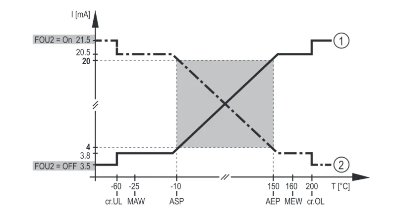
If the measured temperature value is outside the scaled measuring range, the
analogue signal is 20...20.5 mA or 3.8...4 mA (→ Fig.1). When the measured
temperature value continues to increase or decrease, the analogue signal goes to the value 3�5 mA or 21�5 mA�
160 20 4 3�5 21�5 FOU2 = OFF FOU2 = On 20�5 3�8 I [mA] -25 -10 150 MEW 200 cr�OL MAW -60
cr�UL ASP AEP
T [°C]
1
2
Figure 1: output characteristics analogue output with factory setting
1 Setting [OU2] = I 2 Setting [OU2] = Ineg
MAW = initial value of the measuring range, MEW = final value of the measuring range, ASP = analogue start point, AEP = analogue end point
8
5.4 Diagnostic function
The unit continuously checks the temperature measurement (→ 5.4.1 Calibration
check function) and detects further events� In case of deviations from normal operation, a diagnostic message is provided (→ 5.4.2)�
5.4.1 Calibration check function
By measuring with two different, thermically coupled sensor elements (measuring element and reference element) the unit automatically detects temperature
differences during temperature measurement�
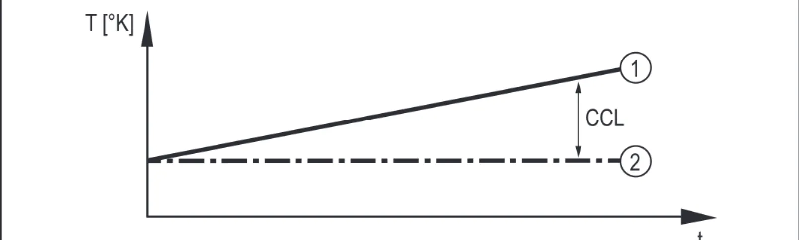
The process value is measured by the measuring element and provided via the analogue output�The reference value is used for comparison purposes and to verify the process value� If the temperature difference between the process value and the reference value exceeds the value set as calibration check limit [ccL], a warning is triggered: The LED changes to blue and the diagnostic output opens�
t T [°K]
CCL 2 1
Figure 2: Calibration check function
Example: Measuring element (1) measures 61�05 °C, reference element (2) measures 60 °C� Setting ccL = 1 K results in a warning�
If a warning is triggered, the LED remains blue, even if the temperature difference drops below the ccL value again� Corrective measures:
Check whether the sensor is to remain in use in the process or to be replaced or do as follows:
► Increase the ccL value so that the LED goes back to green� > The diagnostic output closes�
> The ccL modification is written to the logbook (→ 5.6)�
If the reference element fails, the calibration check function fails as well and the LED changes to blue�
9 UK
Setting range ccL →Technical data.
Due to the usual manufacturing tolerances a temperature difference of max� 0�1 K can also occur with new sensor elements� This does not affect the calibration check function�
To ensure that the calibration check function detects no other influences except the temperature difference between the sensor elements, an internal delay time of 10 minutes has been set�
5.4.2 Diagnostic messages
Diagnostic messages are output as follows: • LED signal:
The LED shows all warnings and alarms by means of a colour change (blue = warning; red = alarm)�
• Diagnostic signal:The diagnostic output provides all warnings and alarms via a switching signal�
• Analogue signal:The analogue output only provides alarms�In case of an alarm the analogue signal goes to 3�5 mA or 21�5 mA�
• IO-Link:If the IO-Link interface is used, all diagnostic messages are displayed via the connected software or provided to the higher-level controller� In
addition, a diagnostic bit is provided that corresponds to the behaviour of the physical switching output�
List of all diagnostic messages readable via IO-Link → IO Device
10
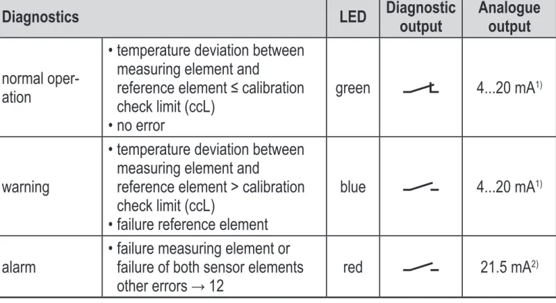
Diagnostics LED Diagnostic output Analogueoutput
normal oper-ation
• temperature deviation between measuring element and
reference element ≤ calibration
check limit (ccL) • no error
green 4���20 mA1)
warning
• temperature deviation between measuring element and
reference element > calibration check limit (ccL)
• failure reference element
blue 4���20 mA1)
alarm • failure measuring element or failure of both sensor elements
other errors → 12 red 21�5 mA
2)
Table 1: diagnostic function
1) For [OU2] = Ineg: 20���4 mA 2) For [FOU2] = OFF: 3�5 mA
Warnings are provided with a delay time of 10 minutes� Alarms are provided immediately�
5.5 Simulation mode
Normal operation and diagnostic function (warnings and alarms) can be simulated based on freely selected parameters using this function�
► Set the requested duration of the simulation with [S�Tim]�
► Set a simulation value for the measuring element or select the simulation of a fault of the measuring element with [TEMP]�
► Set a simulation value for the reference element or select the simulation of a fault of the reference element with [REF_TEMP]�
► Write values to the unit�
► Click on [Start simulation]�
> The simulation runs for the duration set under [S�Tim]�
11 UK • A simulated calibration check warning (LED = blue) is provided with a
delay of 30 seconds�
• A simulated alarm (LED = red) is provided without delay�
• During the simulation, [S�On] = On is displayed in the parameter setting software�
5.6 Binary data transmission (BLOB)
The unit stores the last 20 events and the last 20 calibration check warnings in an internal ring memory�
• In the [Event log], all events are stored including the operating hours and the event number (Events → 12; table)�
• In the [Calibration check alarm log], all calibration check warnings are stored including the operating hours, the measured value, the temperature difference value, the set ccL value and the event status�
6 Installation
► Before installing and removing the unit make sure that no pressure is applied to the system and there is no medium in the pipe�
► Note dangers related to extreme machine / medium temperatures�
6.1 Use in hygienic areas to 3-A
► Make sure that the sensor is integrated into the system according to 3-A�
► Use only adapters with 3-A certification and marked with the 3-A symbol
(→ accessories at www.ifm.com.).
The process connection must be provided with a leakage port� This is ensured when installed using adapters with 3-A approval�
► For use according to 3-A, take note of the corresponding regulations for cleaning and maintenance�
Not suitable for use where the criteria for paragraph E1�2/63-03 of the 3-A standard 63-03 have to be met�
12 1 3 2 4 5
The following applies to units with 3-A certification:
► Only use adapters with 3-A certification for the process connection�
► Do not install the unit at the lowest
point of the pipe or tank (→ position
5) in order that the medium can run off the area of the sensor elements�
6.2 Use in hygienic areas to EHEDG
The sensor is suited for CIP (cleaning in process) when installed correctly�
► Observe the application limits (temperature and material resistance) according to the data sheet�
► Make sure that the sensor is integrated into the system according to EHEDG�
► Use self-draining installation�
► Only use process adapters permitted according to EHEDG with special seals required by the EHEDG position paper�
The gasket of the system interface must not be in contact with the sealing point of the sensor�
► In case of structures in a tank, the installation must be flush mount� If not possible then direct water jet cleaning and cleaning of dead spaces must be possible�
► Leakage ports must be clearly visible and must be installed facing downwards for vertical pipes�
13 UK 1 D L L 2 4 1 2 3 d=6 mm D d=6 mm TCC5xx TCC8xx / TCC9xx
Fig� 1: mounting dimensions for use according to EHEDG
1: sealing ring between the housing and the process connection 2: adapter
3: leakage port 4: PEEK gasket
6.3 Units with clamp process connection
The one-piece units of design TCC8xx with clamp 1�5" and of design TCC9xx with clamp 2" are best suited for a hygienic installation�
► Observe the notes on installation:
→ 6.1 Use in hygienic areas to 3-A → 6.2 Use in hygienic areas to EHEDG
14
6.4 Units with process connection G ½ sealing cone
The units of design TCC5xx can be adapted to standard process connections using two sealing versions: The following applies to both sealing versions:
► Only use accessories from ifm electronic� The optimum function is not ensured when using components from other manufacturers�
► Observe the instructions of the adapter�
The sealing ring between the housing and the process connection (Fig� 1 →
6�2) can compensate for variable insertion depths and tolerances and provides protection against the ingress of media in the thread area�
The sealing ring between the housing and the process connection cannot compensate for the system pressure�
6.4.1 Flush mount hygienic zero-leak using PEEK gasket ► Use the supplied PEEK gasket�
-The PEEK gasket is suited for use in hygienic installations to EHEDG and 3-A�
-The PEEK gasket is long-term stable and maintenance-free�
-When the PEEK gasket is mounted several times, check and replace it if necessary�
-The PEEK gasket has been rated for ifm adapters with end stop towards the medium�
► Use adapters with leakage ports�
► Screw the sensor into the adapter� Recommended tightening torque 20 Nm�
► Observe the notes on installation:
→ 6.1 Use in hygienic areas to 3-A → 6.2 Use in hygienic areas to EHEDG
6.4.2 Flush mount zero-leak using metal-to-metal seal
A long-term stable, maintenance-free and gap-free fitting in the metal-to-metal seal is only valid for once-only mounting�
► Do not use the supplied PEEK gasket�
15 UK
6.5 Units for process adaptation via clamping ring
The units of design TCC2xx can be mounted in the pipe or in the tank directly in contact with the medium via a clamping ring adapter� Mounting examples:
Fig� 2: direct installation
16
7 Electrical connection
The unit must be connected by a qualified electrician�Voltage supply according to EN 50178, SELV, PELV�
The unit is designed exclusively for 3-wire operation�
► Disconnect power�
► Connect the unit as follows:
BN WH BK BU 4 1 3 2 OUT2 L+ L OUT1 Colours to DIN EN 60947-5-2 BK: black BN: brown BU: blue WH: white Pin Assignment
4 (OUT1) • diagnostic signal
• IO-Link signal for temperature measurement and diagnostics 2 (OUT2) • analogue signal for temperature measurement and diagnostics
Circuit examples:
1 1 x positive switching / 1 x analogue 2 1 x negative switching / 1 x analogue
L+ L 3 BU 4 BK 2 WH 1 BN L+ L 3 BU 4 BK 2 WH 1 BN 3 1 x IO-Link / 1 x analogue L+ IO-Link L 3 BU 4 BK 2 WH 1 BN
17 UK
8 Operating and display elements
1
• At the head of the unit is an LED that is green during normal operation�
• If the deviation between the sensor elements is too high, the LED changes to blue (→ 5.4.1
Calibration check function)� • In case of an alarm, the LED
changes to red�
• In case of a shorted circuit, the LED flashes red�
• When the command for identifying a sensor in the plant is used, the LED flashes green�
1: LED (green, blue, red)
9 Parameter setting
Parameters can be set via the IO-Link interface before installation and set-up of the unit or during operation�
If you change parameters during operation, this will influence the function of the plant�
► Ensure that there will be no malfunctions in your plant�
During parameter setting the unit remains in the operating mode� It continues to monitor with the existing parameter until the parameter setting has been completed�
► Connect the unit to a parameter setting software via suitable hardware�
18
9.1 Parameters
Parameter Explanation
ou2 Configuration of the analogue signal: I = 4���20 mA or Ineg = 20���4 mA or OFF = output off
P-n Switching logic for the diagnostic output: PnP or nPn� ASP2 Analogue start point for measured temperature value� AEP2 Analogue end point for measured temperature value�
FOU2 Analogue signal in case of an alarm: On = 21�5 mA; OFF = 3�5 mA� ccL Calibration check limit = temperature deviation between the process
value and the reference value from which the unit provides a warning� uni Setting of the standard unit of measurement: °C or °F�
LED mode The LED on the unit can be switched on and off: On = LED always on
Off = LED always off
Notification = LED only on in case of a warning or an alarm� Restore Factory
Settings Restore the factory settings�We recommend recording your own settings before carrying out a reset (→ 14 Factory setting)�
9.2 Analysis functions
Displays /
commands Explanation
Free-text fields for
device information -Application Specific Tag -Function Tag -Location Tag
-Installation date
Diagnostics display -Hi = highest temperature value measured -Lo = lowest temperature value measured
Flash On / Flash Off The LED starts flashing, allowing easy identification of the unit in the field�
Reset
-[Hi] and [Lo] memory -[Hi] memory
-[Lo] memory
19 UK
Displays /
commands Explanation
Simulation Simulation of temperature measurement (measuring element and reference element) and diagnostic cases without opera-tion → 5.5 Simulation mode�
Protocols
(log entries) -Device status -Detailed device status -Event history
-Operating hours since first set-up
-Operating hours history memory (sampling rate 1 s) -Internal temperature
-Parameter configuration faults Binary file transfer
(BLOB) Command for storing a log file on all calibration check warn-ings or events → 5.6�
10 Operation
When the supply voltage is applied, the unit is in the RUN mode after a power-on delay time of 6 s (= normal operating mode)� It carries out its measurement and evaluation functions and provides output signals according to the set parameters�
11 Technical data
→ Technical data at www.ifm.co.
12 Troubleshooting
The unit has many self-diagnostic options� It monitors itself automatically during operation (→ 5.4 Diagnostic function)�
Diagnostic messages are indicated via the LED (LED blue = warning; LED red = alarm)�
These messages are also available via IO-Link�
► Connect the unit to a PC and read it via the IO-Link interface�
20
Diagnostics Event LED Corrective measures
calibration check warning
(temperature deviation between the two sensor elements exceeds ccL)
0x8CAE
(36014) blue ► check the unit and adapt ccL, if necessary
► replace unit failure reference element 0x5010
(20496) blue ► prepare replacement of the unit failure measuring element 0x5010
(20496) red ► replace unit hardware failure of the unit 0x5000
(20480) red ► replace unit
parameter error 0x6320
(25376) red ► check the validity of the set parameter values (→ data
sheet)
short circuit 0x7710
(30480) flashes red ► check the installation measuring range significantly
exceeded (process value exceeds cr�OL or does not reach cr�UL →
5�3, Fig� 1)
0x8C20
(35872) red ► check the temperature range PV Overrun (process value
ex-ceeds MEW → 5.3, Fig�1) 0x8C10(34576) no effect* ► check the temperature range PV Underrun (process value does
not reach MAW → 5.3, Fig� 1) 0x8C30(34608) no effect* ► check the temperature range internal unit temperature too high
(> 125°C / 257°F) 0x4210(16912) no effect* ► remove the heat source
simulation active 0x8C01
(35841) no effect** ► terminate the simulation mode flashing function for sensor
localisation active 0x8CDB(36059) flashes green ► terminate the flashing function with the "Flash Off" command
* LED colour depends on the current operating status� ** LED colour depends on the simulated operating status� MAW = initial value of the measuring range
21 UK
13 Maintenance, repair and disposal
If used correctly, no maintenance and repair measures are necessary� Only the manufacturer is allowed to repair the unit�
► After use dispose of the unit in an environmentally friendly way in accordance with the applicable national regulations�
► Define regular calibration intervals according to the process requirements�
14 Factory setting
Parameter Factory setting User setting
OU2 I ASP -10 °C AEP 150 °C ccL 1 K FOU2 On P-n PnP Uni °C LED On
Simulation mode reference value: 20 °C process value: 20 °C S�Tim: 3 min