Sharif University of Technology
Scientia IranicaTransactions F: Nanotechnology http://scientiairanica.sharif.edu
On the vibration of postbuckled functionally
graded-carbon nanotube reinforced composite annular
plates
R. Gholami
a;and R. Ansari
ba. Department of Mechanical Engineering, Lahijan Branch, Islamic Azad University, Lahijan, P.O. Box 1616, Iran. b. Faculty of Mechanical Engineering, University of Guilan, Rasht, P.O. Box 3756, Iran.
Received 30 May 2018; received in revised form 4 January 2019; accepted 22 April 2019
KEYWORDS Free vibration of postbuckled nanocomposite annular plate; Postbuckling behavior;
Carbon nanotube-reinforced composites; Numerical approach; GDQ method.
Abstract. This paper studies the free vibration characteristics of post-buckled Func-tionally Graded (FG) carbon nanotube (CNT) reinforced annular plates. The analysis was performed by employing a Generalized Dierential Quadrature (GDQ)-type numerical technique and pseudo-arc length scheme. The material properties of FG-carbon nanotube reinforced composite (CNTRC) plates were evaluated by an equivalent continuum approach based on the modied rule of mixture. The vibration problem was formulated based on the First-order Shear Deformation Theory (FSDT) for moderately thick laminated plates and von Karman nonlinearity. By employing Hamilton's principle and a variational approach, the nonlinear equations and associated Boundary Conditions (BCs) were derived, which were then discretized by the GDQ method. The postbuckling behavior was investigated by plotting the secondary equilibrium path as the deection-load curves. Thereafter, the free vibration behaviors of pre- and post-buckled FG-CNTRC annular plates were examined. Eects of dierent parameters including types of BCs, CNT volume fraction, an outer radius-to-thickness ratio, and an inner-to-outer radius ratio were investigated in detail.
© 2019 Sharif University of Technology. All rights reserved.
1. Introduction
Since the discovery of carbon nanotubes (CNTs) by Iijima in 1991 [1], considerable advances have been made in the realm of nanotechnology. CNTs are the most extraordinary materials that have been discovered by mankind over the past thirty years. Characterized by extraordinary properties, they have attracted a great deal of attention from the scientic community and beyond [2-5]. These materials have the potential
*. Corresponding author. Tel./Fax: +98 1342222906 Email address: gholami r@liau.ac.ir (R. Gholami) doi: 10.24200/sci.2019.51145.2029
to revolutionize dierent elds such as medicine, elec-tronics, material science, energy storage, etc. CNTs are reported to enjoy many desired properties such as high tensile strength and Young's modulus. The high strength of CNTs makes them the stiest known ber discovered so far. Further, CNTs enjoy excellent thermal and electrical conducting properties and can either show metallic or semi-conducting behavior based on their size, chirality, and purity. Thus, CNTs can be used as reinforcements to enhance the physical and mechanical properties and electrical conductivity of the polymeric structures. Because of some charac-teristics such as wear and corrosion resistance, low density, light weight, and low cost, polymer-based composites are extensively utilized in the industrial and
engineering usages including marine and automotive technologies, military, and the agricultural industry [6]. The addition of CNTs to polymers may result in the enhancement of many mechanical, electrical, and optical properties of polymer-based nanocomposites. These superior properties make them the best can-didate for use in various usages such as actuators, biomedical devices, chemical sensors, and smart mem-ory devices [7,8]. Ajayan et al. [9] fabricated carbon nanotube reinforced composites (CNTRCs) for the rst time in 1994. Since then, a number of studies have been performed to utilize CNTs as reinforcement for various materials such as polymer, ceramic, and metals. For instance, Hassanzadeh-Aghdam and Mahmoodi [10] conducted a comprehensive analysis of the mechanical properties of CNT-reinforced metallic nanocomposites by proposing an analytical approach. The eects of CNT volume fraction, interphase, and geometry on the thermal expansion behavior of CNT-reinforced metallic composites were studied by Hassanzadeh-Aghdam et al. [11,12]. Foroughi et al. [13] experimentally exam-ined the inuence of CNTs on the mechanical and bioactive properties of bioglass-ionomer cement. More-over, AfzaliTabar et al. [14] investigated the CNTs and nano-porous graphene on the silica nanohybrid Picker-ing emulsion. Recently, Raee et al. [15] experimen-tally studied the vibrational and damping behaviors of functionalized multi-walled CNT-reinforced epoxy nanocomposites as the passive damping components.
Among the published papers on the mechani-cal characteristics of CNT-reinforced composites, the majority have been devoted to the reinforcement of polymers by CNTs [16-24]. This is because of the relative ease of polymer processing, which demands lower temperatures for consolidation compared to met-als and ceramic matrix composites. The fascinating mechanical properties of CNTs over carbon bers have resulted in increasing use of CNT-reinforced composite structures. The main dierence between these two types of composites lies in the low quantity of CNTs used in the CNTRCs [25-27]. Meguid and Sun [28] stated that by increasing the CNT volume fraction beyond a specied limit, the mechanical properties of CNTRCs will deteriorate. As a result, the concept of Functionally Graded (FG) materials has been incorpo-rated in the modeling of CNTRCs in order to use CNTs more eciently in the reinforced composites. The local buckling of CNTRC beams induced by the bending was studied by Vodenitcharova and Zhang [29]. The imperfection sensitivity of the primary resonances of FG-CNTRC beams under periodic transverse loading was examined by Gholami et al. [30]. A Mori-Tanaka-based equivalent model was utilized by Formica et al. [31] to study the free vibration of CNTRC plates. Their study showed that the maximum enhancement of the properties of ber composites was obtainable by
uniformly aligning CNTs with the loading direction. Ansari et al. [32] examined the nonlinear forced vi-bration of Timoshenko beams made of FG-CNTRCs. Shen and He [33] studied the nonlinear vibration of embedded FG-CNTRC curved panels under thermal loading. It was found that nonlinear vibration behavior of CNTRC panels was considerably aected by the FG-CNT reinforcements. The nonlinear forced vibration of FG-CNTRC rectangular plates based upon Mindlin and Reddy's plate theories was analyzed by Ansari et al. [34,35]. In addition, Ansari et al. [36] ana-lytically studied the postbuckling of piezoelectric FG-CNTRC shells. Lin and Xiang [37] investigated the free vibrational characteristics of SWCNT-reinforced nanocomposite beams. The variational technique of Hamilton's principle and sense of von Karman's non-linearity were used to derive the energies of the CNT-reinforced composite beams. Then, by employing the p-Ritz technique, the free vibration problem of the beam was solved. The free vibration of FG-CNTRC cylindrical shells under the thermal loading was ana-lyzed by Song et al. [38] upon employing the assumed modes approach. Mehrabadi et al. [39] examined linear buckling of FG-CNTRC plates under uniaxial and biaxial compression. In a study conducted by Lie et al. [40], free vibrations of SWCNT-reinforced nanocom-posite plates were analyzed by the kp-Ritz method. Shen et al. [41] presented a study on the vibrational response of thermally postbuckled sandwich CNTRC plates resting on the elastic mediums. Ahmadi et al. [42] employed a multi-scale nite element procedure to obtain the mechanical properties of carbon ber-CNT-polyimide nanocomposites and, then, examine the buckling of rods made of these nanocomposites. Recently, according to a variational approach, Gholami and Ansari [43] provided a weak form of mathematical modeling to study the nonlinear resonant responses of shear deformable FG-CNTRC annular sector plates. In addition, the resonance of multi-scale laminated nanocomposite rectangular plates was examined by Gholami et al. [44]. According to the First-order Shear Deformation Theory (FSDT) and Rayleigh-Ritz scheme, the free vibration of nanocomposite spherical panels and shells of revolution was studied by Wang et al. [45].
In this work, upon employing the Generalized Dierential Quadrature (GDQ) approach, the free vibration problem of postbuckled FG-CNTRC annular plates with Uniformly Distributed (UD) and FG rein-forcements is numerically formulated. It is assumed that the material properties of FG-CNTRCs are ob-tained by employing a modied rule of mixture-based equivalent model. The postbuckling problem is for-mulated on the basis of the FSDT with a von Karman type of kinematic nonlinearity. By applying Hamilton's principle, the nonlinear equations and corresponding
BCs are derived and, then, discretized by the GDQ method. In addition, pseudo-arc length algorithm is employed to nd the secondary equilibrium paths of CNTRCs plates. The free vibration of postbuckled CNTRC annular plates is formulated as a standard lin-ear eigenvalue problem. Impacts of design parameters including type of BCs, CNT volume fraction, inner-to-outer radius ratio, and inner-to-outer radius-to-thickness ratio on the equilibrium postbuckling path and fundamental frequencies in the pre- and post-buckled congurations are investigated.
2. Mathematical formulation
2.1. CNTRCs and material properties
As illustrated in Figure 1, an SWCNT-reinforced com-posite annular plate with inner radius, a, outer radius, b, and thickness, h, is assumed. It is considered that the SWCNT reinforcements are UD or FG through the thickness. The structure of the CNT signicantly aects the properties of the nanocomposites. Thus far, dierent micromechanical models such as the Mori-Tanaka [46,47] and Voigt models, as well as the rule of the mixture [26,48], have been proposed to obtain the material properties of CNTRCs. The former is used for micro-particles and the latter extensively for the CNTRCs. On a nanoscale, both of these approaches should be extended to capture the small-scale eect. It has been demonstrated that both of Mori-Tanaka and Voigt techniques have an identical level of accuracy in treating the static and dynamic problems of FG ceramic-metal beams [49], plates [50], and shells [51]. Accordingly, applying the modied version of the rule of mixture, one can express the eective Young's and
Figure 1. Schematics of an FG-CNTRC annular plate.
shear modules of CNTRCs as follows [48]:
E11= 1VcntE11cnt+ VmEm; (1a)
2
E22 =
Vcnt
Ecnt 22 +
Vm
Em; (1b)
3
G12 =
Vcnt
Gcnt 12 +
Vm
Gm: (1c)
By considering this point that, through theformula-tions, sub-/super-scripts \m" and \cnt" signify the matrix and CNT, respectively, in Eq. (1), G and E rep-resent shear and Young's modules, and j(j = 1; 2; 3)
identies the CNT eciency parameter, which is attributed to the scale-dependent properties. It is notable that j will be later obtained by matching
the material properties achieved from the Molecular Dynamics (MD) simulations with those obtained from the rule of mixture. In addition, Vcnt and Vm denote
the volume fractions of CNT and mixture, respectively, and have the following relationship as follows:
Vcnt+ Vm= 1: (2)
The FG-CNTRCs are supposed to be in two dierent congurations, namely O and X types. For conve-nience, in the following, the two types of FG-CNTRCs are indicated by FGO and FGX. For the case, the FG-CNTRC is referred to as FGO, and the middle surface of the composite is CNT-rich, while, for the FGX, both outer and inner faces are CNT-rich. In this study, the UD, FGO, and FGX distributions of CNTs are of special concern and are expressed as below [48]:
UD : Vcnt= Vcnt ; (3a)
FGO : Vcnt= 2
1 2 jzj h
V
cnt; (3b)
FGX : Vcnt =4 jzjh Vcnt ; (3d)
where: V
cnt= cnt
cnt+
cnt
m cnt
m
cnt
: (4)
In the preceding equation, cnt is the mass fraction
of CNT, and denotes the mass density. Similar to the previous case, eective Poisson's ratios and are obtained by Wang and Shen [52]:
12= Vcnt12cnt+ Vmm; 21= 12E22=E11; (5)
2.2. Nonlinear equations of motion and corresponding BCs
Consider a cylindrical coordinate system (r; ; z) in which its origin is placed at the center of the mid-plane of the FG-CNTRC annular plate, and r, , and z-axes denote radial, tangential, and thickness directions, respectively. Considering the axisymmetric deformation, the displacement components, ur, uand
uz, along r; , and z axes, respectively, are obtained by
Liew et al. [53]:
ur= u (t; r) + z r(t; r) ; u= 0; uz= w (t; r) ; (7)
where u(t; r) and w(t; r) are the radial and transverse displacement components of middle-plane, respectively, and r(t; r) is the rotation about -axis. In addition,
t denotes time. Of note, the displacement eld dened in Eq. (7) is based on the FSDT.
By applying Eq. (7), the strain-displacement re-lations are expressed by:
"r= @u@r +12
@w
@r 2
+ z@ @rr; "=ur + z rr;
"rz= "zr= 12
r+@w@r
: (8)
Additionally, according to the linear elasticity and the von Karman hypothesis, the nonlinear stress compo-nents can be dened by:
8 < : r rz 9 = ; = 2
4QQ1112 QQ1222 00
0 0 Q55
3 5 8 < : "r " "rz 9 =
; ; (9)
where:
Q11= 1 E11
1221; Q22=
E22
1 1221;
Q12= 1 21E11
1221; Q55= G13: (10)
In the previous equation, parameters Eij, Gij, and ij
are obtained through Eqs. (1) and (5).
Based on the previous discussion, now, the in-plane force resultants (Nr; N), moment resultants
(Mr; M), and transverse force resultant (Qr) are
obtainable by: N = Nr N = h=2 Z h=2 r dz; M = Mr M = h=2 Z h=2 r zdz;
Qr = s h=2
Z
h=2
rzdz; (11)
where s = 2=12 denotes the shear correction
fac-tor [53]. By inserting Eqs. (9) and (10) into Eq. (11), one obtains:
Nr=A11
" @u @r + 1 2 @w @r 2#
+ A12ur + B11@ @rr
+ B12 rr;
N=A22ur + A12
" @u @r + 1 2 @w @r 2#
+ B22 rr
+ B12@ @rr;
Mr=B11
" @u @r + 1 2 @w @r 2#
+ B12ur + D11@ @rr
+ D12 rr;
M=B22ur + B12
" @u @r + 1 2 @w @r 2#
+ D22 rr
+ D12@ @rr;
Qr= ksA55
r+@w@r
; (12)
where:
(Aij; Bij; Dij) = h=2
Z
h=2
Qij 1; z; z2dz; (i; j = 1; 2) ;
Aij = h=2
Z
h=2
Qijdz; (i; j = 5) : (13)
The strain energy (s) expression for the FG-CNTRC
annular plates takes the following form: s= 12
Z
S h=2
Z
h=2
ij"ijdzdS
= 12 Z S Nr " @u @r + 1 2 @w @r 2#
+ Nur + Mr@ @rr
+ M rr + Qr
r+@w@r
dS;
(14) where S denotes the plate area. The kinetic energy, T, and the potential energy, w, resulting from the
applied external radial load, N0
T =12 Z S ( I0 "@u @t 2 + @w @t 2#
+ 2I1@u@t@w@t + I2
@ r
@t 2) dS; (15a) w= Z S " 1 2Nr0
@w
@r 2#
dS: (15b)
Using Hamilton's principle [54]:
t2
Z
t1
(T s+ w) dt = 0; (16)
where denotes the variation operator; one can achieve the governing equations and all possible BCs. By inserting Eqs. (14) and (15) into (16), taking the variation of u, w, and r through the integration by
parts, and lastly by equating the coecients of u, w, and rto zero, the following expressions are obtained
for the governing equations of motion (Eqs. (17a)-(17c)) and the BCs (Eqs. (18a)-(18c))
@Nr
@r +
Nr N
r = I0
@2u
@t2 + I1
@ r
@t2; (17a)
@Qr @r + Qr r + 1 r @ @r rNr@w@r
+ N0
r
@2w
@r2 +
1 r
@w @r
= I0@ 2w
@t2; (17b)
@Mr
@r +
Mr M
r Qr= I2
@ r
@t2 + I1
@2u
@t2; (17c)
and:
u = 0 or Nr= 0; (18a)
w = 0 or Nr+ Nr0 @w@r + Qr= 0; (18b)
r= 0 or Mr= 0: (18c)
By inserting Eq. (12) into Eqs. (17), the governing equations are determined in terms of displacement components as follows:
A11
@2u
@r2 +
1 r @u @r + @w @r
@2w
@r2 +
1 2r @w @r 2
+ B11
@2 r
@r2 +
1 r
@ r
@r
A22ru2
B22r2r A2r12
@w
@r 2
= I0@ 2u
@t2 + I1
@ r
@t2; (19a)
ksA55
@2w
@r2 +
1 r
@w @r +
@ r
@r + rr
+ N (w) + N0
r
@2w
@r2 +
1 r
@w @r
= I0@
2w
@t2; (19b)
B11
" @2u
@r2 +
1 r @u @r+ @w @r
@2w
@r2 +
B11 2r @w @r 2#
B22ru2 D22r2r+ D11
@2
r
@r2 +
1 r
@ r
@r B12 2r @w @r 2
ksA55
r+@w@r
= I2@ @t2r + I1@ 2u
@t2; (19c)
where: N (w) =
( A11 " @u @r + 1 2 @w @r 2#
+ A12ur
+ B11@ @rr + B12 rr
) 1 r
@w @r +
@2w
@r2 + ( A11 @2u
@r2 +
@w @r
@2w
@r2
+ A12
1 r @u @r u r2
+ B11@ 2 r
@r2
+ B12
1 r
@ r
@r 1 r2 r
) @w
@r: (20)
The BCs provided in Eq. (18) show the possible edge conditions for the FG-CNTRC annular plates. Consequently, the BCs are as follows:
For the simply supported CNTRC annular plates:
Nr= w = Mr= 0: (21a)
For clamped CNTRC annular plates:
Nr= w = r= 0: (21b)
The following dimensionless quantities are introduced so as to non-dimensionalize the governing equations of motion:
= rb; = hb; fu; wg ! h fu; wg ;
r= r; Nr0= N 0 r
A110; =
t b
r A110
I10 ;
fa11; a22; a12; a55g = fA11; A22A; A12; A55g 110 ;
fd11; d22; d12; d55g = fD11A; D22; D12g 110h2 ;
I0; I1; I2 =
I0
I00;
I1
I00h;
I2
I00h2
; (22)
where A110 and I00 show the values of A11 and I0 for
a homogeneous matrix plate. Thus, one obtains: a11
" @2u
@2 +
1 @u @ + 1 @w @
@2w
@2 +
1 2 @w @ 2#
+ b11
@2 r
@r2 +
1
@ r
@
a22u2 b222r
A12 2 @w @ 2
= I0@ 2u
@2 + I1
@ r
@2; (23a)
ksa55
@2w
@2 +
1
@w
@ +
@ r
@ + r
+ N0 r
@2w
@2 +
1 @w @ +1 a11 " @u @ + 1 2 @w @ 2#
+ a12u
+ b11@ @r + b12 r 1@w@ +@ 2w
@2
+1
a11
@2u
@2 +
1
@w @
@2w
@2
+ a12
1 @u @ u 2 + b11@
2 r
@2
+ b12
1
@ r
@ 2r
@w
@ = I0 @2w
@2; (23b)
b11
" @2u
@2 +
1 @u @ + 1 @w @
@2w
@2 +
1 2 @w @ 2#
b22u2 d222r + d11
@2
r
@2 +
1
@ r
@ d12 2 @w @ 2
ksa55
r+@w@r
= I2@ @2r + I1@ 2u
@2: (23c)
Further, by non-dimensionalizing the BCs, the follow-ing expressions are obtained for the simply supported
(Eq. (24a)) and clamped (Eq. (24b)) BCs: a11 " @u @ + 1 2 @w @ 2#
+ a12u + b11@ @r
+ b12 r = w = 0;
b11 " @u @ + 1 2 @w @ 2#
+ b12u + d11@ @r
+ d12 r = 0; (24a)
a11 " @u @ + 1 2 @w @ 2#
+ a12u + b11@ @r + b12 r
= w = r= 0: (24b)
3. GDQ method
The GDQ method as an ecient numerical approach can be utilized for solving the boundary value problems including the ordinary and partial dierential equa-tions. Unlike the nite element method that is usually employed for solving the weak form of equations, the GDQ technique represents a powerful tool for solving the equations in the strong form with great eciency and accuracy using a small number of discrete mesh points [55].
3.1. Introduction
With the aid of the GDQ technique [56-58], the pth order derivative of g(r) is attained in the following form:
@pg (p)
@pp
r=ri
=XN
j=1
Ar
ijg (rj) ; (25)
where N is the number of total discrete points. By considering a column vector F:
F = [gj] = [g (rj)] = [g (r1) ; g (r2) ; : : : ; g (rN)]T;
(26) where gj= g(rj) indicates the amount of g(r) at rj, and
an operational matrix of dierentiation on the basis of Eq. (25) is achieved as in the following form:
@p
@rp (F) = DprF = [Drp]i;jfFjg ; (27)
where: Dp
r= [Drp]i;j= Apij; i; j = 1 : N; (28)
where Aij gives the weighting coecients obtained as
by Eq. (29) as shown in Box I, in which P(ri) =
N
j=1;j6=i(ri rj), and Ir denotes an N N identity
Apij = 8 > > > > > > > < > > > > > > > :
Ir; r = 0
P(ri)
(ri rj)P(rj); i 6= j and i; j = 1; : : : ; N and p = 1 p
A1
ijAp 1ii A p 1 ij ri rj
; i 6= j and i; j = 1; : : : ; N and p = 2; 3; : : : N 1 N
P j=1;j6=iA
p
ij; i = j and i; j = 1; : : : ; N and p = 1; 2; 3; : : : N 1
(29)
Box I
3.2. Postbuckling analysis
With the aid of Chebyshev-Gauss-Lobatto points as the grid points, the mesh generation can be obtained by:
i = +1 2
1 cos i 1
N 1
; i = 1 : N; (30) where = a=b. The discretized form of displacement components is dened as the following vectors:
UT= [U
1; : : : ; UN] ;
WT= [W
1; : : : ; WN] ; T = [
1; : : : ; N; ] ; (31)
where Ui = u (i) ; Wi = w (i) ; i = (i). By
assuming N0
r = P , utilizing the GDQ scheme, and
discarding the inertia terms, the equilibrium equations are discretized by:
a11
D2
U + D1U A1+1 D2W
D1
W
+21 D1 W
D1
W
A1
+ b11 D2 + D1 A1 a22U A2
b22 A2 a212 D1W
D1
W
A1=0; (32a)
sa55 D2W + D1W A1
+ sa55 D1 + A1
PD2
W + D1W
A1
+1
a11
D1
U + 21 D1W
D1
W
+ b11D1 + a12U A1+ b12 A1
D2
W + D1W
A1
+1
a11
D2
U +1 D2W
D1
W
+ a12D1U A1 U A2+ b11D2
+ a12D1U A1 U A2
+ b12D1 A1 A2 D1W
= 0;
(32b) b11
D2
U + D1U A1+1 D2W
D1
W
+ 1
2 D1W
D1 W
A1
+ d11 D2 + D1 A1 b22U A2
d22 A2 b212 D1W
D1
W
A1
sa55 + D1W
= 0; (32c)
where shows the Hadamard product [59] and AT i =
1=i
1; 1=i2; : : : ; 1=Ni
. Following the same procedure used for the discretization of the equilibrium equation, one can discretize the BCs (Eqs. (18)) similarly. The set of nonlinear equations of the domain can be dened by:
G : R3N+1! R3N;
G (P; X) = 0;
XT=UT; WT; T; (33)
where parameter P is the axial load.
The previous equation due to the presence of P is a parameterized equation. Here, by employing the pseudo-arc length continuation technique, this equation will be solved. To this end, by substituting the residual of equations relevant to boundaries into the residual of the domain G(P; X), the edge conditions are satised. This assumption implies that the elements of
G related to the grid points must be substituted with those of discretized BCs.
3.3. Vibration study in the postbuckled region Herein, the aim is to examine the linear free vibration of a buckled CNTRC plate. To accomplish this goal, by introducing small disturbances ud, wd, and d,
respectively, around the buckled congurations us, ws,
and s, the time evolution of that disturbance will be
obtained as follows:
u (; ) = us() + ud(; ) ; w (; )
= ws() + wd(; ) ; r(; )
= s() + d(; ) : (34)
Thereafter, by inserting the previous equation into the governing equation and ignoring the nonlinear time-dependent terms, the linear free vibration problem is obtained by:
mx + kx = 0; (35)
where dot indicates the derivative with respect to , x denotes the generalized coordinate, and m and k are the inertia and stiness matrices, respectively, which can be determined by:
xT= [u
d; wd; d] ;
m = 2
4 I00 I00 I01 I1 0 I2
3 5 ; k =
2
4 kkwuuu kkwwuw kkw u k u k w k
3
5 : (36)
The elements of k are introduced as follows: kuu= a11
@2
@2 +
1
@ @
a2212;
kuw=a11
@2w
s @2 @ @ + @ws @ @2
@2+
1 @ws @ @ @ a12 @ws @ @ @; ku = b11
@2
@2 +
1
@ @
b2212: (37a)
kwu=1
a11@@ +a12 1@w@s +@ 2w s @2 +1
a11 @ 2
@2 + a12
1 @ @ 1 2 @ws @ ;
kww=ksa55
@2
@2 +
1
@ @
+a112
1
@ws
@ +
@2w s @2 @ws @ @ @ +a112
@ws
@ @2
@2 +
@2w s @2 @ @ @ws @ +1 ( a11 " @us @ + 1 2 @ws @ 2#
+ a12us
+ b11@ @s + b12 s
) 1 @ @ + @2 @2 P @2
@r2 +
1 r @ @r +1 a11 @2u
s
@2 +
1
@ws
@ @2w
s
@2
+ a12
1 @us @ us 2 + b11@
2 s
@2
+ b12
1
@ s
@ 2s
@ @; kw =1
b11@@ + b121 1@w@s +@ 2w
s
@2
+1
b11 @ 2
@2+ b12
1 @ @ 1 2 @ws @ + ksa55
@ @ + 1 ; (37b)
k u = b11
@2
@2 +
1 @ @ b22 2;
k w =b11
@ws
@ @2
@2+
@2w s @2 @ @ + 1 @ws @ @ @ d12 @ws @ @
@ ksa55 @ @; k = d222 + d11
@2
@2 +
1
@ @
ksa552: (37c)
Now, by employing the GDQ technique, one can discretize Eq. (35) as follows:
M X + KX = 0; (38)
in which: XT=UT
d; wTd; Td
;
M = 2 4 I0D
0
0 I1D0
0 I0D0 0
I1D0 0 I1D0
3 5 ;
K = 2
4 KKwuuu KKwwuw KKw u K u K w K
3
5 : (39)
The components of K are determined by: kuu= a11 D2+ A1}D1
a22A2}D0;
kuw=a11
D2
Ws}D1+ D1Ws}D2
+ A1 D1Ws}D1
a12
A1 D1Ws}D1
; ku = b11 D2+ A1}D1
b22A2}D0; (40a)
kwu=1 a11D1+ a12A1
} A1 D1Ws+ D2Ws
+1a11D2+ a12 A1}D1 A2}D0
} D1 Ws;
kww=ksa55 D2+ A1}D1
+a112 D2
Ws+ A1 D1Ws D1Ws
}D1
+a112 D1Ws}D2+ D2Ws}D1
D1
Ws+1
a11
D1
Us
+ 1
2 D1Ws
D1
Ws+ a12A1
D0
Us+ b11D1 s+ b12A1 D0 s
} D2
+ A1}D1
+1
a11
D2
Us+1 D1Ws D2Ws
+ a12 A1 D1Us A2 D0Us
+ b11D2 s+ b12
A1 D1 s
A2 D0 s}D1 P D2+A1}D1
; (40b) kw =ksa55 D1+ A1+1b11D1 + b12A1
} D2
Ws+ A1 D1Ws
+1
b11D2+ b12
A1
}D1
A2}D0
} D1
Ws;
k u= b11 D2+ A1}D1
b22A2}D0;
k w=b11
D1
Ws}D2+ D2Ws}D1+ A1
D1
Ws}D1
d12
A1 D1Ws }D1
ksa55D1;
k = d22A2+ d11 D2+ A1}D1
ksa552D0;
(40c) where } represents the SJT product (SJT is the abbreviation of Shanghai Jiao Tong Univ.) [59,60]. By considering the harmonic solution of the form X =
~
Xei!, Eq. (39) turns into:
!2M ~X + K ~X = K !2M ~X = 0; (41)
where ! denotes the non-dimensional frequency. Substitution of the BCs into K and M and the rearrangement of the discretized equations and the associated BCs yield the following eigenvalue problem:
Kdd Kdb
Kbd Kbb
~Xd
~ Xb
=
!2MddX~d
f0g
; (42)
where subscripts d and b are the domain and boundary mesh grid points, respectively.
Eq. (42) can be uncoupled through the following expressions:
(
Kdd Kdb(Kbb) 1Kbd
~
Xd= !2MddX~d
~
Xb= (Kbb) 1KbdX~d:
(43) Now, !i(i = 1; 2; 3; : : :) and their corresponding mode
shapes ~XT =hX~T d; ~XTb
i
can be achieved by nding a solution to Eq. (43).
4. Numerical results and discussion
The formulation and solution procedure developed in the previous sections are utilized to present the numerical results for the postbuckling behavior and the free vibration of the FG-CNTRC annular plates. Eects of various factors on the static equilibrium post-buckling path and frequencies are shown by conducting a non-dimensional study. Poly methyl methacrylate (PMMA) with m = 0:34; m = 1150 kg=m3; Em =
2:5 GPa [26] and armchair (10,10) SWCNTs with cnt = 0:175; Gcnt
12 = 1:9445 TPa; Ecnt11 =
5:6466 TPa; Ecnt
22 = 7:08 TPa; cnt = 1400 kg=m3 at
room temperature (300 K) [61] are selected as matrix and reinforcements, respectively.
Furthermore, the values of CNT eciency param-eters 1, 2, and 3 for three dierent CNT volume
fractions are considered as follows [26]: V
cnt= 0:12 : 1=0:137; 2=1:022 ; 3= 0:715;
V
cnt= 0:17 : 1=0:142; 2=1:626 ; 3= 1:138;
V
cnt= 0:28 : 1=0:141; 2=1:585 ; 3= 1:109:
In what follows, a sequence of letters including \SS" and \C" is used to represent the simply supported and clamped BCs, respectively.
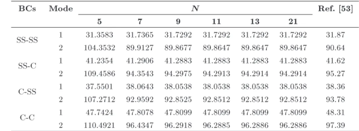
To provide a convergence study and illustrate the accuracy of mathematical modeling, solution pro-cedure, and numerical results, the natural frequency parameters of isotropic annular plates are provided in Table 1. It can be seen that the results are converged by increasing N and are in excellent agreement with those of Liew et al. [53]. In this study, N = 21 is used in all computational eorts. In addition, in Table 2, the critical buckling load parameters associated with various inner-to-outer radius ratios are compared with those given in [62], illustrating very well agreement.
Depicted in Figure 2 are the static equilibrium postbuckling paths as the maximum non-dimensional
Table 2. Comparison of critical buckling load parameter ( ~Pcr= Pcrb2=D110) of C-C isotropic annular plates
( = 0:3; b=h = 20).
a=b Present Ref. [62] 0.2 59.922 60.01 0.3 76.633 76.77 0.4 101.812 102.05
deection, wmax, versus the non-dimensional
compres-sive radial load (Non. dim. radial load; P = P =A110
where P is the dimensional compressive radial load) for the three dierent prescribed distributions of CNTs in the CNTRC annular plates corresponding to four various combinations of simply supported and clamped edge supports. According to this gure, it is revealed that for a xed value of the radial load, the maximum deection, wmax, corresponding to an FGO-CNTRC
annular plate is larger than those of the other two types of CNTRC plates; the FGO-CNTRC annular has the lowest critical buckling load and the highest critical buckling load, and the maximum load-carrying capac-ity belongs to the FGX distribution pattern. It can be concluded from this gure that the addition of more CNTs to the upper and lower surfaces of FG-CNTRC annular plates results in a considerable increase in the total stiness of system and induces more resistance against bending. In addition, it is observed that the FG-CNTRC plates with C-C edge conditions have min-imum values of maxmin-imum deection and, subsequently, maximum values of critical buckling load, whereas, for the case of the FG-CNTRC annular plates with fully simply supported edges, an opposite trend is seen. The dependence of the non-dimensional frequency (Non. dim. frequency: ! = !bpI00=A110 where ! denotes
the natural frequency) upon the non-dimensional com-pressive radial load in the pre- and post-buckled states is exhibited in Figure 3. Based on the results exhibited in Figure 3, it can be concluded that the fundamental frequencies of FG-CNTRC annular plates in the pre-Table 1. Convergence of the frequency parameters~! = !b2pI
00=D110
of isotropic annular plates with dierent BCs ( = 0:3; b=h = 5; a=b = 0:5).
BCs Mode N Ref. [53]
5 7 9 11 13 21
SS-SS 1 31.3583 31.7365 31.7292 31.7292 31.7292 31.7292 31.87 2 104.3532 89.9127 89.8677 89.8647 89.8647 89.8647 90.64 SS-C 1 41.2354 41.2906 41.2883 41.2883 41.2883 41.2883 41.62 2 109.4586 94.3543 94.2975 94.2913 94.2914 94.2914 95.27 C-SS 1 37.5501 38.0643 38.0538 38.0538 38.0538 38.0538 38.36 2 107.2712 92.9592 92.8525 92.8512 92.8512 92.8512 93.78 C-C 1 47.7424 47.8078 47.8099 47.8099 47.8099 47.8099 48.31 2 110.4921 96.4347 96.2918 96.2885 96.2886 96.2886 97.39
Figure 2. Equilibrium postbuckling path of FG-CNTRC annular plates for three dierent distributions of the CNTs (b=h = 40; V
cnt= 0:17; a=b = 0:2).
Figure 3. Vibration behavior of pre- and post-buckled FG-CNTRC annular plates for three dierent distributions of the CNTs (b=h = 40; V
buckled state decrease with an increase in the radial load. This is because the stiness of FG-CNTRC annular plates decreases by increasing the compressive radial loading. By increasing the compressive radial load to a new high, the stiness matrix becomes a zero matrix at a certain point, called the buckling point. In this point, the FG-CNTRC annular plates do not experience any vibration and, consequently, the fundamental frequency is zero. It can be interpreted that the buckling point is a bifurcation point through which the FG-CNTRC annular plate meets its sec-ondary equilibrium state known as the postbuckling region. Prior to the bifurcation point, the frequencies correspond to the pre-buckling conguration, and those after the critical buckling load are concerned with the vibration in the post-buckled state. For a buckled plate, it is seen that by increasing the compressive radial load, the fundamental frequencies increase. This implies that a buckled plate can withstand additional load without failure. In addition, it is deduced that the dimensionless frequency-load curves are continuous, yet not dierentiable at the buckling point. According to this gure, it is observed that at a xed value of radial load, the fundamental frequencies associated with the FGO-CNTRC plates have lower values than CNTRC annular plates with FGX and UD patterns in the pre-buckled region. While, in the postpre-buckled region, it is seen that the fundamental frequencies corresponding to
FGO-CNTRC plates have larger values than the other two cases. It is due to this fact that the deection in the postbuckled region intensies the nonlinear stiness matrices. In addition, it is implied that the eect of deection is more signicant than the CNT distribution pattern. Hence, at a certain point in the postbuckled region, since the deection of FGO-CNTRC annular plate is more than two other distribution patterns, its frequency is greater than the annular plate with UD and FGX patterns.
Eects of V
cnt on the equilibrium postbuckling
path and frequency-response curves are plotted in Figures 4 and 5 for the FGX-CNTRC annular plates. From these gures, it is seen that as V
cnt increases,
the maximum dimensionless deection decreases and critical buckling load increases. It means that by increasing V
cnt, the exibility of the CNTRC annular
plate increases, too. This is due to the considerable stiness of CNTs. As it is expected, by increasing V
cnt,
the frequencies of the CNTRC annular plates with FGX pattern increase in the pre-buckled region, whereas an opposite trend is observed for the postbuckling conguration.
Figures 6 and 7 show the eects of b=h on the maximum dimensionless deection and frequency of the FGO-CNTRC plates with C-C, SS-SS, C-SS, and SS-C BCs, respectively. It is observed that an increase in b=h leads to increasing and decreasing the maximum
Figure 4. Postbuckling path of FGX-CNTRC annular plates for dierent amounts of V
Figure 5. Free vibration of pre- and post-buckled FGX-CNTRC annular plates for various values of V cnt
(b=h = 40; a=b = 0:3).
Figure 6. Postbuckling characteristics of FGX-CNTRC annular plates for various values of b=h (V
Figure 7. Free vibration response of pre- and post-buckled FGX-CNTRC annular plates for dierent values of b=h (V
cnt= 0:17; a=b = 0:2).
dimensionless deection and the critical buckling load, respectively. In other words, an increase in b=h results in a decrease in the postbuckling load-carrying capacity of FGannular plates. According to the dimensionless frequency-radial load curves, it is seen that the frequency in the pre-buckled and post-buckled regions respectively decreases and increases as the plate aspect ratio rises.
Finally, the eects of a=b on the equilibrium postbuckling path and vibration characteristics of the FGX-CNTRC annular plates with C, SS-SS, C-SS, and SS-C BCs are shown in Figures 8 and 9, respectively. It is deduced that an increase in a=b decreases the maximum dimensionless deection and increases the critical buckling load. In other words, the larger the dierence between the outer and inner radii, the more stable the CNTRC plate. In addition, it is seen that increasing a=b causes the fundamental frequency to increase in the pre-buckled and deep post-buckled regions. In the post-post-buckled region, depending on the geometry and compressive radial loading (and, consequently, the deection of plate), the fundamental frequency may decrease or increase.
5. Conclusion
In this study, a numerical methodology was adopted to investigate the postbuckling and free vibration of
FG-CNTRC annular plates with dierent BCs. To this end, the FSDT along with the von Karman geometric nonlinearity was utilized to formulate the underlying problem. The UD, FGO, and FGX distributions of SWCNTs in the composite plates were considered. Upon employing an equivalent continuum model, the material properties of FG-CNTRCs were estimated. Governing equations were attained by Hamilton's prin-ciple and, then, discretized by a GDQ-based method. Prior to examining the vibration behavior of post-buckled CNTRC plates, postbuckling analysis was performed to obtain the buckling load and equilibrium postbuckling path via the pseudo-arc length continua-tion scheme. Thereafter, the free vibracontinua-tion problem of the postbuckled CNTRC annular plates was solved as a standard linear eigenvalue equation. Eects of various parameters including types of BCs, CNT volume frac-tion, outer radius-to-thickness ratio, and inner-to-outer radius ratio on the postbuckling path and fundamental frequencies were investigated. Results showed that at a xed value of the applied radial load, the fundamental frequencies of FGO-CNTRC plates are the smallest in the pre-buckling region and the largest in the post-buckling region among the given cases. In addition, it was observed that by increasing the outer radius-to-thickness aspect ratio, the fundamental frequencies increase in the prebuckling and deep postbuckling regions.
Figure 8. Postbuckling behavior of FGX-CNTRC annular plates for various values of a=b (b=h = 40; V
cnt= 0:28).
Figure 9. Vibration characteristics of pre- and post-buckled FGX-CNTRC annular plates for various values of a=b (b=h = 40; V
References
1. Iijima, S. \Helical microtubules of graphitic carbon", Nature, 354, pp. 56-58 (1991).
2. Bianco, A., Kostarelos, K., and Prato, M. \Applica-tions of carbon nanotubes in drug delivery", Current Opinion in Chemical Biology, 9, pp. 674-679 (2005).
3. Treacy, M.J., Ebbesen, T., and Gibson, J. \Excep-tionally high Young's modulus observed for individual carbon nanotubes", Nature, 381, p. 678 (1996).
4. Baughman, R.H., Zakhidov, A.A., and De Heer, W.A. \Carbon nanotubes-the route toward applications", Science, 297, pp. 787-792 (2002).
5. Salvetat, J.-P., Bonard, J.-M., Thomson, N., et al. \Mechanical properties of carbon nanotubes", Applied Physics A, 69, pp. 255-260 (1999).
6. Li, Y., Wang, Q., and Wang, S. \A review on
enhancement of mechanical and tribological properties of polymer composites reinforced by carbon nanotubes and graphene sheet: Molecular dynamics simulations", Composites Part B: Engineering, 160, pp. 348-361 (2018).
7. Deep, N. and Mishra, P. \Evaluation of mechanical properties of functionalized carbon nanotube rein-forced PMMA polymer nanocomposite", Karbala In-ternational Journal of Modern Science, 4, pp. 207-215 (2018).
8. Hassanzadeh-Aghdam, M.K., Ansari, R., and Mah-moodi, M.J. \Thermo-mechanical properties of shape memory polymer nanocomposites reinforced by carbon nanotubes", Mechanics of Materials, 129, pp. 80-98 (2019).
9. Ajayan, P., Stephan, O., Colliex, C., et al. \Aligned carbon nanotube arrays formed by cutting a polymer resin-nanotube composite", Science, 265, pp. 1212-1214 (1994).
10. Hassanzadeh-Aghdam, M. and Mahmoodi, M. \A
comprehensive analysis of mechanical characteristics of carbon nanotube-metal matrix nanocomposites", Materials Science and Engineering: A, 701, pp. 34-44 (2017).
11. Hassanzadeh-Aghdam, M.K., Ansari, R., and Mah-moodi, M.J. \Thermal expanding behavior of carbon nanotube-reinforced metal matrix nanocomposites-A micromechanical modeling", Journal of Alloys and Compounds, 744, pp. 637-650 (2018).
12. Hassanzadeh-Aghdam, M., Ansari, R., and Mahmoodi, M. \Micromechanical estimation of biaxial thermo-mechanical responses of hybrid ber-reinforced metal matrix nanocomposites containing carbon nanotubes", Mechanics of Materials, 119, pp. 1-15 (2018).
13. Foroughi, M.R., Khoroushi, M., Nazem, R., et al. \The eect of carbon nanotubes/bioglass nanocomposite on mechanical and bioactivity properties of glass ionomer cement", Scientia Iranica, 23, pp. 3123-3134 (2016).
14. AfzaliTabara, M., Alaeib, M., Khojasteha, R.R., et al. \Preference of nanoporous graphene to Single-Walled Carbon Nanotube (SWCNT) for preparing silica nanohybrid Pickering emulsion for potential Chemical Enhanced Oil Recovery (C-EOR)", Scientia Iranica, 24, pp. 3491-3499 (2017).
15. Raee, M., Nitzsche, F., and Labrosse, M. \Eect of functionalization of carbon nanotubes on vibration and damping characteristics of epoxy nanocomposites", Polymer Testing, 69, pp. 385-395 (2018).
16. Nasihatgozar, M., Daghigh, V., Eskandari, M., et al. \Buckling analysis of piezoelectric cylindrical compos-ite panels reinforced with carbon nanotubes", Interna-tional Journal of Mechanical Sciences, 107, pp. 69-79 (2016).
17. Wu, H., Kitipornchai, S., and Yang, J. \Imperfection sensitivity of thermal post-buckling behaviour of func-tionally graded carbon nanotube-reinforced composite beams", Applied Mathematical Modelling, 42, pp. 735-752 (2017).
18. Wu, H.L., Kitipornchai, S., and Yang, J. \Thermal buckling and postbuckling analysis of functionally graded carbon nanotube-reinforced composite beams", Applied Mechanics and Materials, 846, p. 182 (2016).
19. Wang, M., Li, Z.-M., and Qiao, P. \Semi-analytical solutions to buckling and free vibration analysis of carbon nanotube-reinforced composite thin plates", Composite Structures, 144, pp. 33-43 (2016).
20. Alibeigloo, A. and Liew, K. \Elasticity solution of free vibration and bending behavior of functionally graded carbon nanotube-reinforced composite beam with thin piezoelectric layers using dierential quadra-ture method", International Journal of Applied Me-chanics, 7, pp. 1550002 (2015).
21. Jalali, S. and Heshmati, M. \Buckling analysis of circular sandwich plates with tapered cores and func-tionally graded carbon nanotubes-reinforced compos-ite face sheets", Thin-Walled Structures, 100, pp. 14-24 (2016).
22. Mehar, K., Panda, S.K., and Mahapatra, T.R. \Ther-moelastic deection responses of CNT reinforced sand-wich shell structure using nite element method", Scientia Iranica, 25, pp. 2722-2737 (2018).
23. Hassanzadeh-Aghdam, M., Mahmoodi, M., and
Ansari, R. \Micromechanical characterizing the eec-tive elastic properties of general randomly distributed CNT-reinforced polymer nanocomposites", Probabilis-tic Engineering Mechanics, 53, pp. 39-51 (2018).
24. Hassanzadeh-Aghdam, M., Mahmoodi, M., and
Ansari, R. \Micromechanics-based characterization of mechanical properties of fuzzy ber-reinforced com-posites containing carbon nanotubes", Mechanics of Materials, 118, pp. 31-43 (2018).
25. Griebel, M. and Hamaekers, J. \Molecular dynam-ics simulations of the elastic moduli of polymer-carbon nanotube composites", Computer Methods in Applied Mechanics and Engineering, 193, pp. 1773-1788 (2004).
26. Han, Y. and Elliott, J. \Molecular dynamics simula-tions of the elastic properties of polymer/carbon nan-otube composites", Computational Materials Science, 39, pp. 315-323 (2007).
27. Bonnet, P., Sireude, D., Garnier, B., et al. \Ther-mal properties and percolation in carbon nanotube-polymer composites", Applied Physics Letters, 91, p. 201910 (2007).
28. Meguid, S. and Sun, Y. \On the tensile and shear strength of nano-reinforced composite interfaces", Mater. Design., 25, pp. 289-296 (2004).
29. Vodenitcharova, T. and Zhang, L. \Bending and local buckling of a nanocomposite beam reinforced by a single-walled carbon nanotube", International Journal of Solids and Structures, 43, pp. 3006-3024 (2006).
30. Gholami, R., Ansari, R., and Gholami, Y. \Nonlinear resonant dynamics of geometrically imperfect higher-order shear deformable functionally graded carbon-nanotube reinforced composite beams", Composite Structures, 174, pp. 45-58 (2017).
31. Formica, G., Lacarbonara, W., and Alessi, R. \Vi-brations of carbon nanotube-reinforced composites", Journal of Sound and Vibration, 329, pp. 1875-1889 (2010).
32. Ansari, R., Shojaei, M.F., Mohammadi, V., et al. \Nonlinear forced vibration analysis of functionally graded carbon nanotube-reinforced composite Timo-shenko beams", Composite Structures, 113, pp. 316-327 (2014).
33. Shen, H.-S. and He, X. \Large amplitude free vibra-tion of nanotube-reinforced composite doubly curved panels resting on elastic foundations in thermal envi-ronments", Journal of Vibration and Control, 23, pp. 2672-2689 (2017).
34. Ansari, R., Hasrati, E., Shojaei, M.F., et al. \Forced vibration analysis of functionally graded carbon nanotube-reinforced composite plates using a numer-ical strategy", Physica E: Low-dimensional Systems and Nanostructures, 69, pp. 294-305 (2015).
35. Ansari, R. and Gholami, R. \Nonlinear primary res-onance of third-order shear deformable functionally graded nanocomposite rectangular plates reinforced by carbon nanotubes", Composite Structures, 154, pp. 707-723 (2016).
36. Ansari, R., Pourashraf, T., Gholami, R., and Shaha-bodini, A. \Analytical solution for nonlinear postbuck-ling of functionally graded carbon nanotube-reinforced composite shells with piezoelectric layers", Composites Part B: Engineering, 90, pp. 267-277 (2016).
37. Lin, F. and Xiang, Y. \Numerical analysis on nonlinear free vibration of carbon nanotube reinforced composite beams", International Journal of Structural Stability and Dynamics, 14, p. 1350056 (2014).
38. Song, Z., Zhang, L., and Liew, K. \Vibration anal-ysis of CNT-reinforced functionally graded composite cylindrical shells in thermal environments", Interna-tional Journal of Mechanical Sciences, 115, pp. 339-347 (2016).
39. Mehrabadi, S.J., Aragh, B.S., Khoshkhahesh, V., et al. \Mechanical buckling of nanocomposite rectangular plate reinforced by aligned and straight single-walled carbon nanotubes", Composites Part B: Engineering, 43, pp. 2031-2040 (2012).
40. Lei, Z., Liew, K., and Yu, J. \Free vibration analysis of functionally graded carbon nanotube-reinforced com-posite plates using the element-free kp-Ritz method in thermal environment", Composite Structures, 106, pp. 128-138 (2013).
41. Shen, H.-S., Wang, H., and Yang, D.-Q. \Vibration of thermally postbuckled sandwich plates with nanotube-reinforced composite face sheets resting on elastic foundations", International Journal of Mechanical Sci-ences, 124, pp. 253-262 (2017).
42. Ahmadi, M., Ansari, R., and Rouhi, H. \Studying buckling of composite rods made of hybrid carbon ber/carbon nanotube reinforced polyimide using mul-tiscale FEM", Scientia Iranica, Transactions B (In Press). DOI:10.24200/sci.2018.5722.1444
43. Gholami, R. and Ansari, R. \Geometrically nonlin-ear resonance of higher-order shnonlin-ear deformable func-tionally graded carbon-nanotube-reinforced composite annular sector plates excited by harmonic transverse loading", The European Physical Journal Plus, 133, p. 56 (2018).
44. Gholami, R., Ansari, R., and Gholami, Y. \Numer-ical study on the nonlinear resonant dynamics of carbon nanotube/ber/polymer multiscale laminated composite rectangular plates with various boundary conditions", Aerospace Science and Technology, 78, pp. 118-129 (2018).
45. Wang, Q., Pang, F., Qin, B., et al. \A unied
formulation for free vibration of functionally graded carbon nanotube reinforced composite spherical panels and shells of revolution with general elastic restraints by means of the Rayleigh-Ritz method", Polymer Composites, 39, pp. E924-E944 (2018).
46. Esawi, A.M. and Farag, M.M. \Carbon nanotube rein-forced composites: potential and current challenges", Mater. Design., 28, pp. 2394-2401 (2007).
47. Fidelus, J., Wiesel, E., Gojny, F., et al. \Thermo-mechanical properties of randomly oriented car-bon/epoxy nanocomposites", Composites Part A: Ap-plied Science and Manufacturing, 36, pp. 1555-1561 (2005).
48. Shen, H.-S. \Nonlinear bending of functionally graded carbon nanotube-reinforced composite plates in ther-mal environments", Composite Structures, 91, pp. 9-19 (2009).
49. Librescu, L., Oh, S.-Y., and Song, O. \Thin-walled beams made of functionally graded materials and op-erating in a high temperature environment: vibration and stability", Journal of Thermal Stresses, 28, pp. 649-712 (2005).
50. Shen, H.-S. and Wang, Z.-X. \Assessment of Voigt and Mori-Tanaka models for vibration analysis of
functionally graded plates", Composite Structures, 94, pp. 2197-2208 (2012).
51. Shen, H.-S. \Nonlinear vibration of shear deformable FGM cylindrical shells surrounded by an elastic medium", Composite Structures, 94, pp. 1144-1154 (2012).
52. Wang, Z.-X. and Shen, H.-S. \Nonlinear vibration of nanotube-reinforced composite plates in thermal environments", Computational Materials Science, 50, pp. 2319-2330 (2011).
53. Liew, K.-M., Xiang, Y., Kitipornchai, S., et al., Vi-bration of Mindlin Plates: Programming the p-Version Ritz Method, Elsevier (1998).
54. Reddy, J.N., Mechanics of Laminated Composite
Plates and Shells: Theory and Analysis, CRC press (2004).
55. Gurarslan, G. and Sari, M. \Numerical solutions of lin-ear and nonlinlin-ear diusion equations by a dierential quadrature method (DQM)", International Journal for Numerical Methods in Biomedical Engineering, 27, pp. 69-77 (2011).
56. Bellman, R. and Casti, J. \Dierential quadrature and long-term integration", Journal of Mathematical Analysis and Applications, 34, pp. 235-238 (1971).
57. Shu, C., Generalized Dierential-Integral Quadrature and Application to the Simulation of Incompressible Viscous Flows Including Parallel Computation, Uni-versity of Glasgow (1991).
58. Shu, C. and Richards, B.E. \Application of generalized dierential quadrature to solve two-dimensional in-compressible Navier-Stokes equations", International Journal for Numerical Methods in Fluids, 15, pp. 791-798 (1992).
59. Ansari, R., Gholami, R., Shojaei, M.F., et al. \Coupled longitudinal-transverse-rotational free vibra-tion of post-buckled funcvibra-tionally graded rst-order shear deformable micro-and nano-beams based on the Mindlin's strain gradient theory", Applied Mathemat-ical Modelling, 40, pp. 9872-9891 (2016).
60. Chen, W. and Zhong, T. \The study on the nonlinear computations of the DQ and DC methods", Numerical Methods for Partial Dierential Equations: An Inter-national Journal, 13, pp. 57-75 (1997).
61. Shen, H.-S. and Zhang, C.-L. \Thermal buckling and postbuckling behavior of functionally graded carbon nanotube-reinforced composite plates", Mater. De-sign., 31, pp. 3403-3411 (2010).
62. Ke, L.-L., Yang, J., Kitipornchai, S., et al. \Axisym-metric postbuckling analysis of size-dependent func-tionally graded annular microplates using the physical neutral plane", International Journal of Engineering Science, 81, pp. 66-81 (2014).
Biographies
Raheb Gholami received his BS, MS, and PhD degrees in Mechanical Engineering from University of Guilan, Rasht, Iran in 2008, 2010, and 2015, respec-tively. He is currently a faculty member at the De-partment of Mechanical Engineering, Lahijan Branch, Islamic Azad University. His research background and interests include computational micro- and nano-mechanics, numerical techniques, nonlinear analyses, and prediction of mechanical behavior of beam, plate and shell-type structures.
Reza Ansari received his PhD degree from University of Guilan, Rasht, Iran in 2008, where he is currently a faculty member at the Faculty of Mechanical Engineer-ing. During his PhD program, he was also a visiting fellow at Wollongong University, Australia from 2006 to 2007. He has authored more than 400 refereed journal papers and 12 book chapters. His research background and interests include computational mechanics, numer-ical analysis, continuum mechanics, nano-, micro-, and macro-mechanics.