Installation Guide
For
Ipswitch Failover v9.0.1
©1991-2016 Ipswitch, Inc. All rights reserved.
This document, as well as the software described in it, is furnished under license and may be used or copied only in accordance with the terms of such license. Except as permitted by such license, no part of this publication may be reproduced, photocopied, stored on a retrieval system, or transmitted, in any form or by any means, electronic, mechanical, recording, or otherwise, without the express prior written consent of Ipswitch, Inc.
The content of this document is furnished for informational use only, is subject to change without notice, and should not be construed as a commitment by Ipswitch, Inc. While every effort has been made to assure the accuracy of the information contained herein, Ipswitch, Inc. assumes no responsibility for errors or omissions. Ipswitch, Inc., also assumes no liability for damages resulting from the use of the information contained in this document.
WS_FTP, the WS_FTP logos, Ipswitch, and the Ipswitch logo, MOVEit and the MOVEit logo, MessageWay and the MessageWay logo are trademarks of Ipswitch, Inc. Other products and their brands or company names, are or may be trademarks or registered trademarks, and are the property of their respective companies.
Preface: About This Book...v
Chapter 1: Introduction...7
Ipswitch Failover Concepts...7
Communications...9
Ipswitch Failover Switchover and Failover Processes...11
Chapter 2: Implementation...13
Ipswitch Failover Implementation...13
Environmental Prerequisites...13
Supported Environments...13
Unsupported Environments...13
Minimal VMware Permissions Requirements:...14
Pre-Install Requirements...14
Server Deployment Architecture Options...18
Virtual-to-Virtual...18
Physical-to-Virtual...18
Cloning Technology Options...18
Application Component Options...19
Networking Configuration...19
Local Area Network (LAN)...19
Wide Area Network (WAN)...20
Network Interface Card (NIC) Configuration...21
Firewall Configuration Requirements...22
Anti-Malware Recommendations...22
Chapter 3: Installing Ipswitch Failover ...25
Installing Ipswitch Failover Management Service ...25
Installing Ipswitch Failover ...26
Using the Failover Management Service User Interface...28
Configure Connection to VMware vCenter Server...29
Configure VMware vCenter Converter...30
Protected Servers...32 Manage...32 Summary...69 Status...69 Events...71 Tasks...72 Rules...75 Settings...78 Actions...82
Advanced Management Client...83
Configure the VmAdapter Plug-in...83
Configure Actions to Take Upon Failure of A Rule...84
Configure Actions to Take Upon Failure of a Service...85
Adding an Additional Network Interface Card...87
Appendix A: Installation Verification Testing...89
Testing an Ipswitch Failover Pair...89
Exercise 1 - Auto-switchover...89
Exercise 2 - Data Verification...91
Exercise 3 - Switchover...92
Testing an Ipswitch Failover Trio...92
Exercise 1 - Auto-switchover...93
Exercise 2 - Managed Switchover...94
Exercise 3 - Data Verification...96
The Installation Guide provides information about installing Ipswitch Failover, including implementation in a Local Area Network (LAN) and/or Wide Area Network (WAN). This book provides an overview of installation procedures and guidance for the configuration of Ipswitch Failover when the Secondary and Tertiary servers are virtual.
Intended Audience
This guide assumes the reader has a working knowledge of networks including the configuration of TCP/IP protocols and domain administration, notably in Active Directory and DNS.
Overview of Content
This guide is designed to provide guidance on the installation and configuration of Ipswitch Failover, and is organized into the following sections:
• Preface — About This Book (this chapter) provides an overview of this guide and the conventions used throughout. • Chapter 1 — Introduction presents an overview of Ipswitch Failover concepts including the Switchover and Failover
processes.
• Chapter 2 — Implementation discusses environmental prerequisites and pre-install requirements for installation, options for server architecture, application components, and network configurations. It also gives guidance on anti-malware solutions, and provides a convenient summary of supported configurations as you perform the installation.
• Chapter 3 — Installing describes the installation process, guides you through installation on the Primary, Secondary, and Tertiary (if deployed) servers, and through post-installation configuration.
• Appendix A — Installation Verification provides a quick, simple procedure to verify that Ipswitch Failover is properly installed and initially configured.
Document Feedback
Ipswitch welcomes your suggestions for improving our documentation and invites you to send your feedback to
Abbreviations Used in Figures Description Abbreviation
Ipswitch Channel Channel
Network Interface Card NIC
Physical to Virtual P2V
Virtual to Virtual V2V
Technical Support and Education Resources
The following sections describe technical support resources available to you. To access the current version of this book and other related books, go to http://www.ipswitch.com/support
Online and Telephone Support
Use online support located at http://www.ipswitch.com/support to view your product and contract information, and to submit technical support requests.
Support Offerings
To find out how Ipswitch Support offerings can help meet your business needs, go to http://www.ipswitch.com/support
.
Ipswitch Professional Services
Ipswitch Professional Services courses offer extensive hands-on labs, case study examples, and course materials designed for use as on-the-job reference tools. Courses are available on site, in the classroom, and live online. For the day-to-day operations of Ipswitch Failover, Ipswitch Professional Services provides offerings to help you optimize and manage your Ipswitch Failover servers. To access information about education classes, certification programs, and consulting services, go to http://www.ipswitch.com/support.
Ipswitch Failover Documentation Library
The following documents are included in the Ipswitch Failover documentation library: Purpose
Document
Provides the basics to get Ipswitch Failover up and running. Quick Start Guide
Provides detailed setup information. Installation Guide
Provides detailed configuration and conceptual information. Administrator Guide
Provides help for every window in the Failover Management Service user interface
Online Help
Provides late-breaking information, known issues, and updates. The latest Release Notes can be found at http://www.ipswitch.com/support. Release Notes
Conventions
The documentation uses consistent conventions to help you identify items throughout the printed and online library. Specifying
Convention
Window items including buttons.
Bold
Book and CD titles, variable names, new terms, and field names.
Italics
File and directory names, commands and code examples, text typed by you.
Fixed font
Optional command parameters. Straight brackets, as in [value]
Required command parameters. Curly braces, as in {value}
Exclusive command parameters where only one of the options can be specified.
Chapter
1
Introduction
Ipswitch Failover is a Windows based service specifically designed to provide High Availability and/or Disaster Recovery for server configurations in one solution without any specialized hardware.
Ipswitch Failover provides a flexible solution that can be adapted to meet most business requirements for deployment and management of critical business systems. Capitalizing on VMware vCenter Server's ability to manage virtual infrastructure assets combined with Ipswitch's application-aware continuous availability technology, Ipswitch Failover brings a best in class solution for protecting critical business systems.
Ipswitch Failover Concepts
OverviewIpswitch Failover consists of the Failover Management Service that is used to deploy and manage the Ipswitch Failover nodes that provides for application-aware continuous availability used for protecting critical business systems. The Failover Management Service can be installed on vCenter Server or another Windows server with access to a remote instance of vCenter Server and is accessible via common web browsers.
Using the Failover Management Service User Interface, users can deploy and manage Ipswitch Failover with the ability to view Ipswitch Failover status and perform most routine Ipswitch Failover operations from a single pane of glass.
Figure 1: Deployment Architecture
Ipswitch describes the organization of Ipswitch Failover servers based upon Clusters, Cluster status, and relationships between Clusters. Ipswitch refers to a Cluster of two servers as an Ipswitch Failover Pair or a Cluster of three servers as an Ipswitch Failover Trio. Installing Ipswitch Failover on the servers and assigning an identity to the servers results in an Ipswitch Failover Pair or Trio.
Each server is assigned both an Identity (Primary /Secondary /Tertiary ) and a Role (Active /Passive ). Identity is used to describe the physical instance of the server while the role is used to describe what the server is doing. When the identity is assigned to a server it normally will not change over the life of the server whereas the role of the server is subject to change as a result of the operations the server is performing. When Ipswitch Failover is deployed on a Pair or Trio of servers, Ipswitch Failover can provide all five levels of protection (Server, Network, Application, Performance, and Data) and can be deployed for High Availability in a Local Area Network (LAN) or Disaster Recovery over a Wide Area Network (WAN).
Note: The identity of an existing Disaster Recovery (DR) Secondary server can change under certain
circumstances, such as when a DR pair is extended to become a Trio. In this case, the Secondary server will be re-labeled as the Tertiary, so that the Tertiary is always the DR stand-by in any Trio.
In its simplest form, Ipswitch Failover operates as an Ipswitch Failover Pair with one server performing an active role (normally the Primary server) while the other server performs a passive role (normally the Secondary server).
the server in the passive role serves as the standby server and target for replicated data. This configuration supports replication of data between the active and passive server over the Ipswitch Channel.
When deployed for High Availability, a LAN connection is used. Due to the speed of a LAN connection (normally 100 Mb or more) bandwidth optimization is not necessary.
When deployed in a WAN for Disaster Recovery, Ipswitch Failover can assist replication by utilizing WAN Compression with the built-in WAN Acceleration feature.
Architecture
Ipswitch Failover software is installed on a Primary (production) server, a Secondary (ready-standby) server, and optionally, a Tertiary (also a ready-standby) server. These names refer to the identity of the servers and never change throughout the life of the server (except in the special case described above).
Note: In this document, the term “Cluster” refers to an Ipswitch Failover Cluster. Refer to the Glossary for more information about Ipswitch Failover Clusters.
Depending on the network environment, Ipswitch Failover can be deployed in a Local Area Network (LAN) for High Availability and/or Wide Area Network (WAN) for Disaster Recovery, providing the flexibility necessary to address most network environments.
When deployed, one of the servers performs the Role of the Active server that is visible on the Public network while the other is Passive and hidden from the Public network but remains as a ready-standby server. The Secondary server has the same domain name, uses the same file and data structure, same Public network address (in a LAN), and can run all the same applications and services as the Primary server. Only one server can display the Public IP address and be visible on the Public network at any given time. Ipswitch Failover software is symmetrical in almost all respects, and either the Primary server, Secondary server, or Tertiary server (if applicable) can take the active role and provide protected applications to the user.
Protection Levels
Ipswitch Failover provides the following protection levels:
• Server Protection — provides continuous availability to end users through a hardware failure scenario or operating system crash. Additionally, Ipswitch Failover protects the network identity of the production server, ensuring users are provided with a replica server upon failure of the production server.
• Network Protection — proactively monitors the network by polling up to three nodes to ensure that the active server is visible on the network.
• Application Protection — maintains the application environment ensuring that applications and services stay alive on the network.
• Performance Protection — monitors system performance attributes to ensure that the system administrator is notified of problems and can take pre-emptive action to prevent an outage.
• Data Protection — intercepts all data written by users and applications, and maintains a copy of this data on the passive server which can be used in the event of a failure.
Ipswitch Failover provides all five protection levels continuously, ensuring all facets of the user environment are maintained at all times, and that the Public network continues to operate through as many failure scenarios as possible.
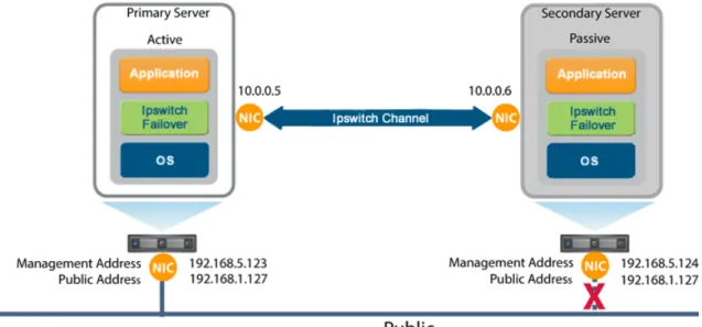
Communications
Ipswitch Failover communications consist of two crucial components, the Ipswitch Channel and the Public network.
To accommodate communications requirements, Ipswitch Failover can be configured with either a single NIC configured with both the Public IP address and the Ipswitch Channel IP address on the same NIC or multiple NICs. Separate NICs can be dedicated for the Public and Channel IP addresses, but this is not a requirement.
Figure 2: Communications Between Primary and Secondary Servers Ipswitch Channel
The first component is the Ipswitch Channel which provides communications between the active and passive servers. The Ipswitch Channel is used for control and data transfer from the active server to the passive server and for monitoring of the active server's status by the passive server.
The Channel IP addresses can be in the same or a different subnet as the Public IP address. NetBIOS will be filtered for the Ipswitch Channel on the active and passive servers to prevent server name conflicts.
The NICs that support connectivity across the Ipswitch Channel can be standard 10/100/1000 Base-T Ethernet cards providing a throughput of up to 1000 Mbits per second across standard Cat-5 cabling or virtual NICs configured on a virtual machine.
When configured for a WAN deployment, if the Channel IP addresses are in the same subnet as the Public IP Address, then they will be routed via the default gateway in a WAN deployment. Alternatively you can configure the Ipswitch Channel to use static routes over switches and routers to maintain continuous communications independent from corporate or public traffic.
Public Network
The second component is the Public network used by clients to connect to the active server. The Public network provides access to the Public IP address used by clients to connect to the active server.
The Public IP address is a static IP address that is only available on the currently active server and is the IP address a client uses to connect to the active server. It must be configured as a static IP address, that is, not DHCP (Dynamic Host Configuration Protocol) enabled. In the figure above, the IP address is configured as
192.168.1.127. The Public IP address is common to the active and passive servers in a LAN and is always available on the currently active server in the cluster. In the event of a switchover or failover, the Public IP address is blocked on the previously active server and is then available on the new active server. When configured, a Management IP address will provide access to a server regardless of the role of the server.
Management IP Address
After installation, all servers in the cluster can be configured with separate Management IP addresses that allow access to the server when the server is in the passive role. The Management IP address is a static IP address in a different subnet than the Public IP address or Ipswitch Channel IP address and is always available for administrators to access the server.
Ipswitch Failover Switchover and Failover Processes
Ipswitch Failover uses four different procedures – managed switchover, automatic switchover, automatic failover, and managed failover – to change the role of the active and passive servers depending on the status of the active server.
• Managed Switchover – You can click Make Active on the Ipswitch Failover Manager Server: Summary page or the Actions drop-down of the Ipswitch Failover Manager Failover Management Service UI to manually initiate a managed switchover. When a managed switchover is triggered, the running of protected applications is transferred from the active machine to the passive machine in the server pair. The server roles are reversed. • Automatic Switchover – Automatic switchover (auto-switchover) is similar to failover (discussed in the next
section) but is triggered automatically when system monitoring detects failure of a protected application. • Automatic Failover – Automatic failover is similar to automatic switchover (discussed above) but is triggered
when the passive server detects that the active server is no longer running properly and assumes the role of the active server.
• Managed Failover – Managed failover is similar to automatic failover in that the passive server automatically determines that the active server has failed and can warn the system administrator about the failure, but no failover actually occurs until the system administrator manually triggers this operation (the default configuration in a DR environment).
Chapter
2
Implementation
This chapter discusses the deployment options and prerequisites to successfully implement Ipswitch Failover and provides a step-by-step process to assist in selecting options required for installation.
Ipswitch Failover Implementation
Ipswitch Failover is a versatile solution that provides multiple configurations to suit user requirements. It can be deployed in a LAN for high availability and/or across a WAN to provide disaster recovery.
During the installation process, Failover Management Service performs a variety of checks to ensure the server meets the minimum requirements for a successful installation. A critical stop or warning message appears if the server fails a check. You must resolve critical stops before you can proceed with setup. Prior to installing Ipswitch Failover, select the deployment options you intend to use. The installation process will prompt you to select options throughout the procedure to create the configuration you want.
Environmental Prerequisites
Ipswitch Failover supports the following environments listed below.
Supported Environments
• Ipswitch Failover is supported on the following versions of Windows Server - Windows Server 2008 R2 Standard/Enterprise//Datacenter
- Windows Server 2012 Standard/Enterprise/Datacenter - Windows Server 2012 R2 Standard/Enterprise/Datacenter
Unsupported Environments
• Ipswitch Failover is not supported across the following:
- A server where Failover Management Service is already running - On a server deployed as a Domain Controller (DC)
- On a server deployed as a Global Catalog
- On a server deployed as a DNS (Domain Name System) Server
Minimal VMware Permissions Requirements:
1. Using the VMware vSphere Client, log into vCenter Server as an Administrator. 2. Navigate to Home > Roles.
3. Select the Read-only role.
4. Right-click the role and click Clone.
5. Rename the new role. For example, Ipswitch Failover. 6. Right-click the newly cloned role and select Edit Role. 7. Add the following privileges:
• Datastore > Allocate Space • Datastore > Browse Datastore • Extension
• Global > Log Event • Network > Assign Network
• Resource > Assign Virtual Machine to Resource Pool • Tasks
• Virtual Machine > Configuration
• Virtual Machine > Interaction > Configure CD Media • Virtual Machine > Interaction > Power On
• Virtual Machine > Interaction > Power Off • Virtual Machine > Inventory
• Virtual Machine > Provisioning
• Virtual Machine > Snapshot Management
8. Map the vCenter Server user account configured in Failover Management Service (FMS) to the newly created Ipswitch Failover role, at the vCenter Server level.
a) Select the top level for vCenter Server, then click the Permissions tab. b) Right-click and select Add Permission.
c) Add the vCenter Server FMS user (if not already present) and assign the newly created Ipswitch Failover role.
Note: You may need to bind the role at the host level (in Hosts and Cluster View) as well as the Datastore
permissions tab level (in Datastores & Datastore Clusters).
Pre-Install Requirements
The following provides a listing of pre-requisites that must be addressed prior to attempting an installation of Ipswitch Failover.
Action Server
An accessible version of vCenter Server 5.1 or later. If running on a Windows Server edition then it must be IFM Service
Action Server
vCenter Server Administrator level user credentials (equivalent with [email protected]) or a user configured with minimal permissions listed in the previous section. Where possible, we recommend vCenter Server Administrator level user credentials (equivalent with Administrator@vsphere)
For P2V installation, VMware Converter 5.5 must be available and configured prior to attempting installation of the Primary server.
Failover Management Service (FMS) supports most browsers used to connect to the FMS web interface but requires that the latest version of Adobe Flash Player be installed.
A local Administrator account (with full admin rights) is required for installation (NOT a domain account nested within groups).
Ipswitch recommends that User Account Control (UAC) be disabled during installation. If it is not possible to disable UAC for installation, open a command window with elevated permissions and launch the Ipswitch-Failover-n.n-nnnnn-x64.msi file from within the command window.
Ipswitch Failover requires that Microsoft™ .Net Framework 4.0 or later be installed prior to installation. Primary
Server If the Primary server has a pending reboot, it must be resolved prior to the deployment of Ipswitch Failover on to the server.
Ipswitch recommends that User Account Control (UAC) be disabled during installation. If it is not possible to disable UAC for installation, you must use the built-in local Administrator account during installation. Enter this account information on the Deploy Failover page.
A local Administrator account (with full admin rights) is required for installation (NOT a domain account nested within groups).
The server to be protected by Ipswitch Failover can NOT be any of the following:
• A server running Failover Management Service
• A server configured as a Domain Controller, Global Catalog, DHCP, or DNS These roles and services must be removed before proceeding with installation.
The Primary server can be Virtual or Physical but the Secondary server will always be created as a Virtual server.
Important: When installing in a Virtual-to-Virtual architecture, VMware Tools must be installed and running
on the Primary server before starting the Ipswitch Failover installation process.
Verify that all services to be protected have all three Recovery settings set to Take no Action.
Verify no other critical business applications except those to be protected by Ipswitch Failover are installed on the server.
Verify that there is a minimum of 2GB of available RAM in addition to any other memory requirements for the Operating System or installed applications. 512MB of RAM must remain available to Ipswitch Failover at all times.
Verify that a minimum 2GB of free disk space is available on the installation drive for Ipswitch Failover.
Note: Although Ipswitch Failover requires only 2GB of available disk space on the drive to receive the
Ipswitch Failover installation, once installed, the size of each send and receive queue is configured by default for 10GB. For Trio configurations the send and receive queues will by default require 20GB per server. You must ensure that sufficient disk space is available to accommodate the send and receive queues or modify the queue size configuration to prevent MaxDiskUsage errors.
Obtain and use local administrator rights to perform Ipswitch Failover installation.
Action Server
Apply the latest Microsoft security updates and set Windows Updates to manual.
All applications that will be protected by Ipswitch Failover must be installed and configured on the Primary server prior to installing Ipswitch Failover.
Verify that all services to be protected are running or set to Automatic prior to installation.
Note: During installation, protected services are set to manual to allow Ipswitch Failover to start and stop
services depending on the role of the server. The target state of the services is normally running on the active server and stopped on the passive.
Register this connection's address in DNS must be disabled on all NICs on the target server.
Note: If deploying in a DR configuration, replace the existing DNS "A" record for the Public IP address
with a static record and configure the TTL to 45 seconds. Otherwise, after installation, re-enable Register this connections's address in DNS.
File and Printer Sharing must be enabled and allowed access through all firewalls on the Primary target server prior to deployment.
Verify that the Server service is running prior to deployment to the target server.
When installing in a P2V environment, the specifications of the Secondary Ipswitch Failover virtual machine must match the Primary physical server as follows:
Secondary Server
• Similar CPU
• Identical Memory
• Enough disk space to host VM disks to match the Primary server
The Secondary Ipswitch Failover virtual machine must have sufficient priority in resource management settings so that other virtual machines do not impact its performance.
IP Address requirements: Public:
IP Addressing
• 1 each Public IP address - Failover Management Service
• 1 each Public IP address - Primary Server
• 1 each Public IP address - Secondary Server (only when deployed for DR)
Note: When deployed for HA or as part of a trio, the Primary and Secondary server will share a Public
IP address.
• 1 each Public IP address - Tertiary Server (only when deployed in a trio) Channel:
• 1 each Channel IP address - per server when deployed in a pair
• 2 each Channel IP addresses - per server when deployed in a trio
When deployed for HA in a LAN environment, Ipswitch Failover is normally configured so that both servers use the same Public IP address. Each server also requires a unique Ipswitch Channel IP address.
LAN
Note: After deployment, on the Public NIC, go to the Network Properties for TCP/IP4 and under Advanced
Properties, select Register this connection's address in DNS for the Public NIC.
When deployed in a WAN environment, persistent static routing configured for the channel connection(s) where routing is required.
Action Server
At least one Domain Controller at the Disaster Recovery (DR) site.
• If the Primary and DR site uses the same subnet:
- During installation, follow the steps for a LAN or vLAN on the same subnet.
- Both the Primary and Secondary servers in the pair use the same Public IP address.
• If the Primary and DR site use different subnets:
- During installation, follow the steps for a WAN.
- The Primary and Secondary servers in the Ipswitch Failover pair require a separate Public IP address and an Ipswitch Channel IP address.
- Provide a user account with rights to update DNS using the DNSUpdate.exe utility provided
as a component of Ipswitch Failover through the Failover Management Service User Interface tasks or Ipswitch Failover Manager Applications > Tasks > User Accounts.
- Ipswitch recommends integrating Microsoft DNS into AD so that DNSUpdate.exe can identify
all DNS Servers that require updating.
If using Windows Firewall, Failover Management Service can automatically configure the necessary ports for traffic. In the event that other than Windows Firewall is being used, configure the following specific ports to allow traffic to pass through:
Firewalls
• From VMware vCenter Server -> Failover Management Service
- TCP 443 / 9727 / 9728 / Ephemeral port range
• From VMware vCenter Server -> The protected virtual machine
- TCP 443 / Ephemeral port range
• From Failover Management Service -> VMware vCenter Server
- TCP 443 / 9727 / 9728 / Ephemeral port range
• From Failover Management Service -> The protected virtual machine
- TCP 7 / 445 / 135-139 / 9727 / 9728 / Ephemeral Port Range
• From the Protected Virtual Machine -> Failover Management Service
- TCP 7 / 445 / 135-139 / 9727 / 9728 / Ephemeral Port Range
• From the Protected Virtual Machine -> VMware vCenter Server
- TCP 443 / Ephemeral port range
• From Protected Virtual Machines -> VProtected Virtual Machines in Duo/Trio and back
- TCP 7 / 52267 / 57348 / Ephemeral port range
• From Management Workstation -> VProtected Virtual Machines in Duo/Trio and back
- TCP 52267 / 57348 / Ephemeral port range
For more detailed information, see IKB-2907 Firewall Configuration Requirements for Ipswitch Failover v9.0 and Later.
Note: The default dynamic ephemeral port range for Windows 2008 and 2012 is ports 49152 through 65535. Important: This list does not include the ports required for the MoveIT application.
Server Deployment Architecture Options
The selected server architecture affects the requirements for hardware and the technique used to clone the Primary server.
Virtual-to-Virtual
Virtual-to-Virtual is the supported architecture if applications to be protected are already installed on the production (Primary) server running on a virtual machine. Benefits to this architecture include reduced hardware cost, shorter installation time, and use of the VMware Cloning for installation.
The Secondary virtual machine will be an exact clone of the Primary server and thus automatically meet the minimum requirements for installation of the Secondary server.
Each virtual machine used in the Virtual-to-Virtual pair should be on a separate ESX host to guard against failure at the host level.
Physical-to-Virtual
The Physical-to-Virtual architecture is used when the environment requires a mix of physical and virtual machines. This architecture is appropriate to avoid adding more physical servers or if you plan to migrate to virtual technologies over a period of time.
The Secondary Ipswitch Failover virtual machine will be created from the Primary server.
• The specifications of the Secondary Ipswitch Failover virtual machine must match the Primary physical server as follows:
- Similar CPU - Identical Memory
• The Secondary Ipswitch Failover virtual machine must have sufficient priority in resource management settings so that other virtual machines do not impact its performance.
Cloning Technology Options
Cloning the Primary server to create a nearly identical Secondary or Tertiary server involves different technologies depending on the selected server architecture.
Cloning Technologies
The following cloning technologies are supported for creating cloned images for use as a Secondary or Tertiary server during the installation of Ipswitch Failover:
• VMware vCenter virtual machine cloning is used when deploying a standby HA or standby DR server in a Virtual-to-Virtual environment.
Important: When installing in a Virtual-to-Virtual architecture, VMware Tools must be installed and
running on the Primary server before starting the Ipswitch Failover installation process.
Note: VMware Converter must be configured prior to attempting installation of the Primary server.
Application Component Options
Ipswitch Failover can accommodate any of the supported plug-ins listed below:
Supported Plug-ins
Ipswitch Failover supports the following list of plug-ins which are installed automatically: • Ipswitch Failover for MOVEitCentral v8.0 for x86 and v8.1 for x64
• Ipswitch Failover for MOVEit DMZ v8.1 • Ipswitch Failover for SQL Server • Ipswitch Failover for MySQL • Ipswitch Failover for IIS • Ipswitch Failover for File Server • Ipswitch Failover for SystemMonitor
Additionally, Ipswitch Failover supports the Ipswitch for Business Application Plug-in which may be installed post deployment.
Networking Configuration
Networking requirements are contingent upon how Ipswitch Failover is deployed. To deploy as a High Availability (HA) solution, a LAN configuration is required. To deploy Ipswitch Failover for Disaster Recovery (DR), a WAN configuration is required. Each network configuration has specific configuration requirements to ensure proper operation.
Note: Ipswitch recommends that the Ipswitch Channel be configured on a different subnet than the Public
network. In the event that this is not possible, see IKB-2527 — Configuring Ipswitch Failover Channel and Public Connections to use the Same Subnet.
When Ipswitch Failover is installed using a single NIC configuration, upon completion of installation, Ipswitch recommends that you add an additional NIC to each server (Primary/Secondary/Tertiary) in order to provide network redundancy and then move the Ipswitch Channel configuration to the newly added NICs. For more information about adding additional NICs to Ipswitch Failover, see Adding an Additional Network Interface Card in this guide.
Local Area Network (LAN)
When deployed for HA in a LAN environment, Ipswitch Failover is configured so that both servers use the same Public IP address. Each server also requires an Ipswitch Channel IP address.
Wide Area Network (WAN)
Ipswitch Failover supports sites with different subnets. In this scenario, the Primary and Secondary servers in the Ipswitch Failover Pair or Secondary and Tertiary in a Trio will require unique Public IP addresses in each subnet and a unique Ipswitch Channel IP address in each subnet for each server.
WAN Requirements
WAN deployments require the following:
• Persistent static routing configured for the channel connection(s) where routing is required
Note: This requirement can be avoided if the channel IP addresses are in the same subnet as the Public
IP address in which case the default gateway can be used for routing. • One NIC (minimum)
• At least one Domain Controller at the Disaster Recovery (DR) site • If the Primary and DR site uses the same subnet:
- During install, follow the steps for a LAN or VLAN on the same subnet
- Both the Primary and Secondary servers in the pair use the same Public IP address • If the Primary and DR site use different subnets:
- During install, follow the steps for a WAN
- The Primary and Secondary servers in the Ipswitch Failover pair require a separate Public IP address and an Ipswitch Channel IP address
- Provide a user account with rights to update DNS using the DNSUpdate.exe utility provided as a component of Ipswitch Failover through the Failover Management Service User Interface tasks or Ipswitch Failover Manager Applications > Tasks > User Accounts
- Ipswitch recommends integrating Microsoft DNS into AD so that DNSUpdate.exe can identify all DNS Servers that require updating
- At least one Domain Controller at the DR site
- Refer to the following articles in the Ipswitch Knowledge Base:
Knowledge base article IKB-1425 – Configuring DNS with Ipswitch Failover in a WAN Environment Knowledge base article IKB-1599 – Configuring Ipswitch Failover to Update BIND9 DNS Servers
Deployed in a WAN
Bandwidth
Ipswitch Failover includes automatic bandwidth optimization in WAN environments. This feature compresses data transferred over the Ipswitch Channel, optimizing the traffic for low bandwidth connections causing some additional CPU load on the active server.
Determine the available bandwidth and estimate the required volume of data throughput to determine acceptable latency for the throughput. Additionally, the bandwidth can affect the required queue size to accommodate the estimated volume of data. Ipswitch recommends making a minimum of 1Mbit of spare bandwidth available to Ipswitch Failover.
Latency
Latency has a direct effect on data throughput. Latency on the link should not fall below the standard defined for a T1 connection (2-5ms for the first hop).
Ipswitch SCOPE Data Collector Service can assist in determining the available bandwidth, required bandwidth, and server workload. For more information about Ipswitch SCOPE Data Collector Service, contact Ipswitch Professional Services.
Network Interface Card (NIC) Configuration
Ipswitch Failover supports use of either multiple NICs or a single NIC.
This release of Ipswitch Failover adds very flexible support for configuring NICs with Public and Channel connections. Here are some possible scenarios:
• Single NIC Installation : Ipswitch Failover is installed on a server having a single NIC, which is shared by both the Public Network and the Ipswitch Channel. This can simplify the install process by avoiding down-time in adding a NIC.
• Adding a NIC post-installation . Using a single NIC results in a potential single point of failure. To prevent a single point of failure, additional NICs can be added post-installation, and the Public and Ipswitch Channel IP addresses distributed across these. See Adding a Network Card.
• Multiple NIC Installation. Ipswitch Failover can be installed on a server with multiple NICs. You can choose which NIC will be used for the Ipswitch Channel connection.
Primary Server
The Primary server is configured with the following connections:
• A Principal (Public) network connection configured with a static Principal (Public) IP address, network mask, gateway address, preferred DNS server address, and secondary (if applicable) DNS server address.
• Ipswitch Channel connection(s) configured with a static IP address in the same or a different subnet than the Principal (Public) IP address, and with a different IP address than the Secondary server channel, and network mask. No gateway or DNS server address is configured where a dedicated NIC is used. NetBIOS will be filtered on the passive server to prevent server name conflicts.
• The Register this connection's addresses in DNS check box must be cleared on the Ipswitch Channel connection(s) prior to installing Ipswitch Failover.
Secondary/Tertiary Server
The Secondary/Tertiary server will have the same number of NICs as the Primary server, with the same names and will be configured as follows:
• A Principal (Public) connection configured with a static IP address, network mask, gateway address, preferred DNS server address, and secondary (if applicable) DNS server address.
Note: If deploying as a pair in a WAN, the Principal (Public) IP address of the Secondary server may be
in a different subnet than the Primary server.
Note: If configured in a trio, the Primary and Secondary servers are configured for LAN deployment and
the Tertiary server is configured for a WAN deployment.
• Ipswitch Channel network connection(s) configured on the same or a separate dedicated NIC with a static IP address in the same or a different subnet than the Secondary/Tertiary Principal (Public) IP address, and with a different IP address than the Primary or Secondary (for Tertiary) server's Ipswitch Channel NIC, and
a network mask. A gateway address and DNS address are not configured by the user. NetBIOS will be filtered to prevent server name conflicts.
• The Register this connection's addresses in DNS check box must be cleared on the Ipswitch Channel connection(s) prior to installing Ipswitch Failover.
Firewall Configuration Requirements
When firewalls are used to protect networks, you must configure them to allow traffic to pass through specific ports for Ipswitch Failover installation and management. If using Windows Firewall, Failover Management Service can automatically configure the necessary ports for traffic. In the event that other than Windows Firewall is being used, configure the following specific ports to allow traffic to pass through:
• Ports 9727 and 9728 for managing Ipswitch Failover from the Failover Management Service • Port 52267 for the Client Connection port
• Port 57348 for the Default Channel port
Important: When installing on Windows Server 2008 R2, Microsoft Windows may change the connection type
from a Private network to an Unidentified network after you have configured the firewall port to allow channel communications resulting in the previously configured firewall changes to be reset for the new network type (Unidentified).
The firewall rules must be recreated to allow traffic to pass through for the Client Connection port and the Default Channel port. Ipswitch recommends that the firewall be configured to allow the Client to connect to the Client Connection port by process, nfgui.exe, rather than by a specific port. To enable Channel communications between servers, change the Network List Manager Policy so that the Ipswitch Channel network is identified as a Private Network, and not the default Unidentified Network, and configure the firewall to allow traffic to pass through on Port 57348, the Default Channel port.
Anti-Malware Recommendations
Consult with and implement the advice of your anti-malware provider, as Ipswitch guidelines often follow these recommendations. Consult the Ipswitch Knowledge Base for up to date information on specific anti-malware products.
Do not use file level anti-malware to protect application server databases, such as Microsoft SQL Server databases. The nature of database contents can cause false positives in malware detection, leading to failed database applications, data integrity errors, and performance degradation.
Ipswitch recommends that when implementing Ipswitch Failover, you do not replicate file level anti-malware temp files using Ipswitch Failover.
The file level anti-malware software running on the Primary server must be the same as the software that runs on the Secondary server. In addition, the same file level anti-malware must run during both active and passive roles.
Configure file level anti-malware to use the Management IP address on the passive server(s) for malware definition updates. If this is not possible, manually update malware definitions on the passive server(s).
• C:\Program Files\Ipswitch\Failover\r2\logs
• C:\Program Files\Ipswitch\Failover\r2\log
Any configuration changes made to a file level anti-malware product on one server (such as exclusions) must be made on the other server as well. Ipswitch Failover does not replicate this information.
Chapter
3
Installing Ipswitch Failover
This chapter discusses the installation process used to implement Ipswitch Failover on Windows Server 2008 R2, Windows Server 2012, and Windows Server 2012R2 when the Secondary or Tertiary server is virtual. Prior to installing Ipswitch Failover, you should identify the deployment options you want so that during the installation process you are prepared to select the required options to achieve your configuration goals.
After selecting implementation options, begin the installation process. During the installation process, Failover Management Service performs a variety of checks to ensure the target server meets the minimum requirements for a successful installation. Should the target server fail one of the checks, a critical stop or warning message appears. You must resolve critical stops before you can proceed with setup.
Installing Ipswitch Failover Management Service
Prerequisites
Prior to attempting installation of Failover Management Service, ensure that the server meets all of the pre-requisites stated in Pre-Install Requirements.
Procedure
To install the Ipswitch Failover:
1. Having verified all of the environmental prerequisites are met, download the Ipswitch Failover Management Service.msi file to an appropriate location.
Note: Install on any server running Windows Server 2008 R2 64-bit or later with connectivity to a vCenter
Server.
2. While logged in as the Local built-in Administrator or Domain built-in Administrator, double-click the
Ipswitch-Failover-[n]-[n]-[nnnnn]-x64.msi file to initiate installation of the Failover Management Service.
The Welcome page is displayed. 3. Click Next.
The End User License Agreement page is displayed.
4. Review the End User License Agreement and select I accept the terms in the License Agreement. Click Next. The Firewall Modification screen is displayed.
5. If using something other than Windows Firewall, manually configure Firewall Rules to allow TCP on Ports
9727 and 9728 at this time. If using Windows Firewall, the Inbound Firewall Rules are created automatically and no actions are necessary. Click Next.
The Administrator Credentials screen is displayed.
6. Enter a Username and Password with Administrator permissions for the target server. Click Next. The Ready to install Failover Management Service screen is displayed.
7. Click Install.
The Installing Failover Management Service screen is displayed. When the installation has finished installing the appropriate components, the Completed the Failover Management Service Setup Wizard screen is displayed. 8. Click Finish.
Once installation of the Failover Management Service is complete, the Failover Management Service User Interface will launch automatically.
9. Login to the Failover Management Service User Interface using a built-in local/domain administrator account. 10. Click on the vCenter button.
The Configure Connection to VMware vCenter Server dialog is displayed.
11. Enter the URL for the VMware vCenter Server. Enter a username and password for an Administrator account on the vCenter Server. Click Next.
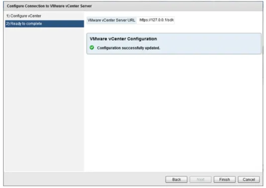
The Ready to complete page is displayed.
12. Click Finish to connect to the VMware vCenter Server.
Installing Ipswitch Failover
Prerequisites
Prior to attempting installation of Ipswitch Failover on the target Primary server, ensure that the server meets all of the pre-requisites stated in Pre-Install Requirements. During the installation process, Failover Management Service will install Ipswitch Failover on the target servers identified in the cluster and validate that the servers meet the minimum requirements for a successful installation.
Procedure
To install Ipswitch Failover on the Primary server:
1. Login to the Failover Management Service UI and select the Manage drop-down. Click on Deploy > Deploy to a Primary server.
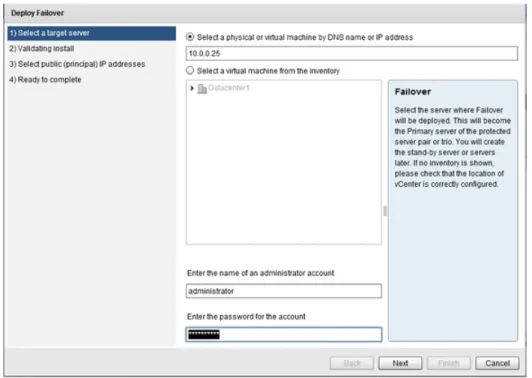
The Deploy Failover page is displayed.
2. Enter the DNS name or IP address of the target (Primary) server, or select a virtual server from the inventory. Enter credentials for a user that is a member of the local Administrator group on the target server and click Next.
The Validating Install page is displayed. The Failover Management Service automatically configures Windows firewalls to allow installation to continue and communications via the Ipswitch Channel and Ipswitch Failover. 3. Once the Validating Install page completes and displays that the server is a valid target, click Next.
The Select Public (Principal) IP Address page is displayed.
4. Validate the Public (Principal) IP address displayed and ensure the check box is selected for addresses that should be available for client connection. Click Next.
The Ready to Complete page is displayed. 5. Review the information and click Next.
The installation of the Primary server proceeds.
7. You have the following options:
• If the Primary server is physical, go to Step 8. • If the Primary server is virtual, go to Step 10.
8. Click on the Converter button. The Configure Connection to VMware vCenter Converter page is displayed. Provide the URL where the VMware vCenter Converter resides and provide the Username and Password with local Administrator permissions on the machine where VMware vCenter Converter is installed. Click Next.
The Ready to Complete screen is displayed. 9. Review the URL and if accurate, click Finish.
Note: The success or failure of connecting to the VMware Converter is indicated as a vSphere Task and
also by the icon shown next to the Converter button. 10. Navigate to Manage > Deploy.
11. Select one of the following depending on the environment you intend to support: • Create a Stand-by VM for High Availability, go to Step 12
• Create a Stand-by VM for Disaster Recovery, go to Step 16
• Create Secondary and Tertiary Stand-by VMs for HA and DR, go to Step 22
Note: You can also create a Stand-by VM for Disaster Recovery for an existing High Availability pair,
and vice-versa.
The Create ... dialog is displayed.
12. Select the Datacenter and Host where the Stand-by server will be created. Click Next. The Select Storage page is displayed.
13. Select a storage location for the virtual machine. Click Next. The Select Channel IP Addresses page is displayed.
14. Enter the Channel IP addresses used to replicate data for the Primary and Secondary servers and select the NIC to which these should be assigned. The Channel IP addresses will be automatically added to the NICs by Ipswitch Failover as a result of the installation process. Click Next.
The Ready to Complete dialog is displayed.
15. Click Finish to initiate the cloning process for creation of a Stand-by server.
Once cloning process is complete, automatic reconfiguration of the Stand-by server will take place requiring only a few minutes to finish. Once complete, perform Post Installation Configuration tasks as listed in this guide.
16. The Create a Stand-by VM for Disaster Recovery dialog is displayed. Select whether the Public (Principal) IP address will be identical to the Primary server or different. If using identical IP addresses, click Next. Otherwise, provide the IP address, NIC to which this should be assigned, Gateway, Preferred DNS Server, and the user account used for updating the DNS server. Click Next.
The Select channel IP addresses page is displayed.
17. Select a network adapter for the channel. Enter the channel IP addresses to be used for the Primary and Secondary servers, and then click Next.
The Select VM move type page is displayed
18. Select whether the new VM will be created at the DR site over the WAN or locally and the .vmdk files manually transported to the DR site, and then click Next.
The Select host page is displayed.
The Select Storage page is displayed.
20. Select a storage location for the virtual machine. Click Next. The Ready to Complete page is displayed.
21. Click Finish to initiate the cloning process for creation of a Stand-by server.
Once cloning process is complete, automatic reconfiguration of the Stand-by server will take place requiring only a few minutes to finish. Once complete, perform Post Installation Configuration tasks as listed in this guide.
22. The Create Secondary and Tertiary VMs for High Availability and Disaster Recovery dialog is displayed. Review the information in the right pane of the dialog, and then click Next.
The Select host page is displayed.
23. Select the Datacenter and Host where the Secondary Stand-by server will be created. Click Next. The Select Storage page is displayed.
24. Select a storage location for the virtual machine. Click Next.
The Configure Tertiary VM page is displayed. Review the information in the right pane and then click Next. The Select public IP address page is displayed.
25. Select whether the public (principal) IP address will be identical to the Primary server or different. If using identical IP addresses, click Next. Otherwise, provide the IP address, Gateway, Preferred DNS Server, and the user account used for updating the DNS server. Click Next.
The Select VM move type page is displayed.
26. Select whether the new VM will be created at the DR site over the WAN or locally and the .vmdk files manually transported to the DR site, and then click Next.
The Select host page is displayed.
27. Select the Datacenter and Host where the Stand-by server will be created. Click Next. The Select Storage page is displayed.
28. Select a storage location for the virtual machine. Click Next. The Configure channel networking page is displayed.
29. Review the information in the right pane of the page, and then click Next. The Primary-Secondary page is displayed.
30. Select a network adapter for the channel. Enter the channel IP addresses to be used for the Primary and Secondary servers, and then click Next.
The Secondary-Tertiary page is displayed.
31. Select a network adapter for the channel. Enter the channel IP addresses to be used for the Secondary and Tertiary servers, and then click Next.
The Tertiary-Primary page is displayed.
32. Select a network adapter for the channel. Enter the channel IP addresses to be used for the Tertiary and Primary servers, and then click Next.
The Ready to complete page is displayed.
33. Review the information on the Ready to complete page and if correct, click Finish. If incorrect, use the Back button to navigate back to the location of the incorrect information.
Using the Failover Management Service User Interface
The Failover Management Service is the primary tool used for deployment and normal daily control of Ipswitch Failover. Most routine operations can be performed from the Failover Management Service User Interface thereby providing a lightweight, easily accessible, method of conducting Ipswitch Failover operations.
Configure Connection to VMware vCenter Server
The Configure Connection to VMware vCenter Server feature provides the ability to connect to VMware vCenter Server and capitalize on vCenter Server features to create virtual Secondary servers from VMware virtual Primary Servers and virtual Tertiary servers from VMware virtual Secondary servers.
Procedure
To configure a connection to VMware vCenter Server:
1. Click the vCenter button to display the Configure Connection to VMware vCenter Server page. 2. Enter the URL for the VMware vCenter Server, the username, and the password for a user account with
administrator privileges on the VMware vCenter Server, and then click Next.
Figure 3: Configure vCenter
Figure 4: Ready to Complete
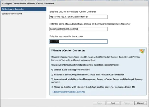
Configure VMware vCenter Converter
Use the Configure VMware vCenter Converter feature to convert physical Primary servers to virtual Secondary and/or Tertiary servers during the cloning process used by Ipswitch Failover to create the Secondary and/or Tertiary servers.
Prerequisites
VMware vCenter Converter 5.5 or later must be installed manually.
Procedure
To configure the VMware vCenter Converter:
Figure 5: Configure VMware vCenter Converter
2. Enter the URL to where VMware vCenter Converter resides.
3. Enter the Username and Password for an account with Administrator permissions on the virtual machine. Click Next.
Figure 6: Ready to Complete
Protected Servers
The Protected Servers pane provides a view of all servers that are currently protected by Ipswitch Failover and managed by Failover Management Service.
To view the status of a protected server, simply select the intended protected server.
Figure 7: Protected Servers
Manage
The Manage drop-down provides access to all of the key functions to deploy Ipswitch Failover and get Ipswitch Failover up and running. It provides the ability to Deploy, Manage, Integrate, and License Ipswitch Failover.
Deploy
The Deploy group is focused on deployment actions and provides the functions to deploy Ipswitch Failover as a Primary, Secondary, or Tertiary server.
Configure Windows Firewall for Deployment
Failover Management Service, by default, automatically configures Windows Firewall rules for RPC Dynamic (recommended). In the event that a non-Windows firewall is being used, you must manually configure firewall rules to allow for deployment and operations.
• Configure the following firewall rules:
• RPC Dynamic is required to allow remote deployment.
• Ports 9727, 9728 for management from Failover Management Service.
Figure 8: Configure Windows Firewall Settings Deploy to a Primary Server
Prerequisites
Prior to attempting installation of Ipswitch Failover on the Primary server, ensure that the server meets all of the pre-requisites stated in the Pre-Install Requirements section of the Ipswitch Failover Installation Guide.
Important: Ipswitch Failover requires that Microsoft™ .Net Framework 4 be installed prior to Ipswitch
Failover installation. If .Net Framework 4 is not installed, Ipswitch Failover will prevent installation until .Net Framework 4 is installed.
Procedure
To Deploy Ipswitch Failover:
1. Having verified all of the environmental prerequisites are met, click on Manage and navigate to Deploy > Deploy to a Primary Server.
The Deploy Failover page is displayed.
Note: When deploying a Primary server, use a built-in local administrator account to successfully deploy
Figure 9: Deploy Ipswitch Failover page
2. Enter the DNS name or IP address of the server that will be the Primary server, or select a virtual server from the inventory. Enter credentials for a user that is a member of the local Administrator group on the target server and click Next.
The Validating Install page is displayed. Ipswitch Failover automatically configures Windows firewalls to allow installation to continue and communications via the Ipswitch Channel and the Failover Management Service.
3. Once the Validating Install dialog completes and displays that the server is a valid target, click Next. The Select public (principal) IP addresses page is displayed.
Figure 11: Select public (principal) IP addresses page
4. Verify that the proper IP address for the Public (Principal) IP address is displayed and that the check box is selected. Click Next.
The Ready to complete page is displayed.
5. Review the information and click Finish. The installation of the Primary server proceeds.
6. Once installation of the Primary server is complete, in the Protected Servers pane, select the Primary server. The Server Summary page is displayed.
Upgrade the Selected Server
Failover Management Service provides a simple process incorporating a wizard to upgrade from previous versions of the product.
1. From the Manage drop-down, navigate to Deploy > Upgrade the selected server. The Upgrade Failover provide credentials page is displayed.
Figure 13: Provide credentials page
2. Enter the name of the local Administrator account and password. After confirming that no users are logged into the Primary, Secondary (or Tertiary) servers, select the check box.
3. Select to either upgrade all server nodes or only a specific server in the cluster. Click Next.
Note: Single node upgrades should only be used in the event the upgrade of the whole cluster has failed.
If you select to upgrade only a specific server in the cluster, you must configure a Management IP address on the target server prior to attempting the upgrade.
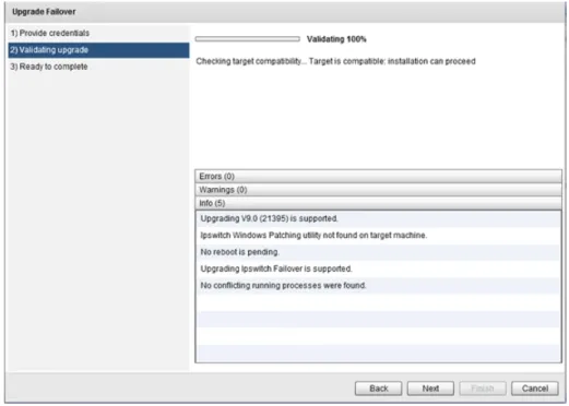
Figure 14: Validating upgrade page
4. Once validation is complete, click Next. The Ready to complete page is displayed.
Figure 15: Ready to complete page
5. Review the information and click Finish to initiate the upgrade of the selected servers.
Uninstall the Selected Server
Procedure
To uninstall the selected server:
1. Select the intended server and from the Manage drop-down, navigate to Deploy > Uninstall the Selected Server.
The Uninstall Selected Server dialog is displayed.
Figure 16: Uninstall the Selected Server
2. Select the Delete Secondary (and Tertiary) VMs (Recommended) option.
3. After verifying that no users are logged onto the Primary, Secondary, or Tertiary (if installed) servers, select the confirmation check box and provide an Administrator account valid on all servers. Click OK.
Ipswitch Failover is uninstalled from the Primary, Secondary and Tertiary (if installed) servers.
Create a Stand-by VM for High Availability
The Create a stand-by VM for high availability feature is used to create a Secondary server when deployed for high availability. Deploying for high availability means that failover will occur automatically when the active server fails. This feature can also be used to add a Stand-by VM for High Availability to an existing Disaster Recovery pair. In this case, the new VM will become the Secondary server and the existing server will be re-labeled as the Tertiary.
Procedure
To create a stand-by VM for high availability:
1. On the Failover Management Service User Interface, click the Manage drop-down and navigate to Deploy > Create a stand-by VM for high availability.
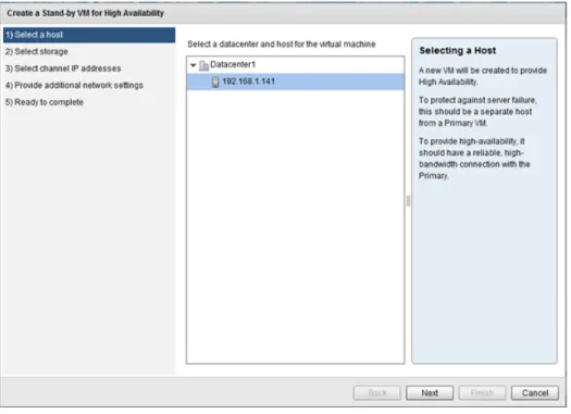
Figure 17: Create a stand-by VM for high availability
2. Select the Datacenter and Host where the Secondary server will be created and click Next. The Select Storage page is displayed.
Note: If the Primary server is a virtual machine, then the Secondary server should be on a separate host
to protect against host failure.
3. Select a storage location for the virtual machine. Click Next. The Select Channel IP Addresses page is displayed.
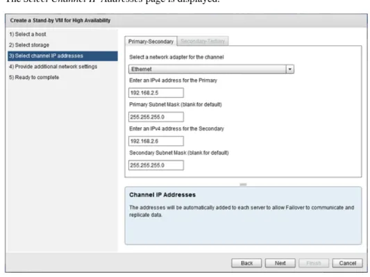
Figure 19: Select Channel IP Addresses
4. Select the NIC which is to host the Channel IP addresses. Enter the Channel IP addresses for the Primary and Secondary servers. Manually enter the subnet mask or leave blank to set to the default subnet mask. If you are adding high-availability to an existing DR pair, enter the IP addresses and associated information for the Secondary-Tertiary Channel. Click Next.
Note: If the IP addresses chosen are not already present on the server's NICs, they will be added
automatically.
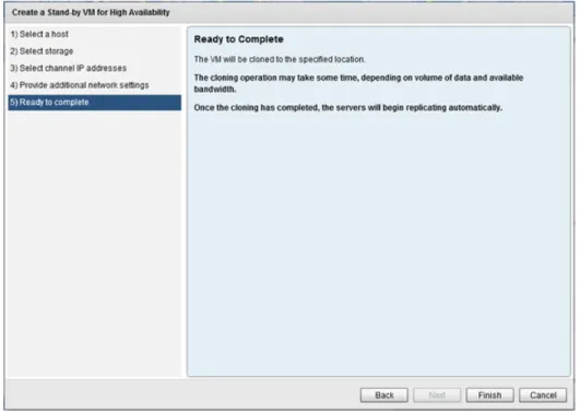
Figure 20: Ready to Complete
5. Click Finish to initiate installation of the Secondary server.
Once installation of the Secondary server is complete, automatic reconfiguration of the Secondary server will take place requiring only a few minutes to complete.
6. Once complete, perform Post Installation Configuration tasks as listed in the Ipswitch Failover Installation Guide.
Create a Stand-by VM for Disaster Recovery
The Create a Stand-by VM for Disaster Recovery feature is used to create a Secondary server when deployed for Disaster Recovery. A Secondary server created for Disaster Recovery will typically be located at a different site from that of the Primary server. By default, automatic failover is disabled between the active and passive servers.
Procedure
To create a stand-by VM for disaster recovery:
1. On the Failover Management Service User Interface, click the Manage drop-down and navigate to Deploy > Create a Stand-by VM for Disaster Recovery.
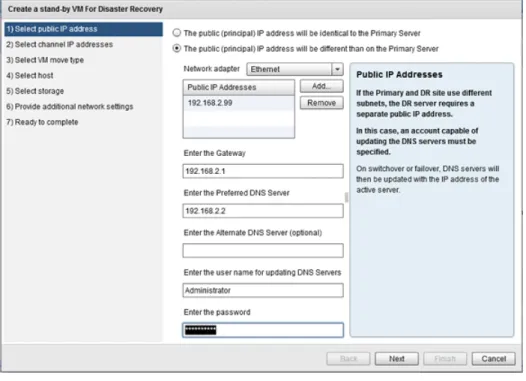
Figure 21: Select Public IP Address page
2. Select whether to use the same Public IP address for the Secondary server that is used for the Primary server or a different Public IP address. Add credentials to be used for updating DNS and Click Next.
The Select Channel IP Addresses page is displayed.
Figure 22: Select Channel IP Addresses page
pair, then enter the IP Addresses and associated information for the Primary-Tertiary and Secondary-Tertiary channels. Click Next.
The Select VM Move Type page is displayed.
Figure 23: Select VM Move Type page
4. Select whether to clone the Primary server to create a Secondary server and power-on the Secondary server or to clone the Primary server to create the .vmdk files to be ported manually to the DR site. Click Next.
Note: If you have selected to move the .vmdk files, this refers to where the files will be created, not the final destination.
Figure 24: Select Host page
5. Select a Datacenter and Host for the virtual machine. Click Next. The Select Storage page is displayed.
Figure 25: Select Storage page
6. Select the storage location for the virtual machine. Click Next. The Ready to Complete page is displayed.
Figure 26: Ready to Complete page
7. Review the information on the Ready to Complete page and if accurate, click Finish to create the Secondary server.
Create Secondary and Tertiary VMs for HA and DR
This feature works to extend capabilities of Ipswitch Failover to incorporate both High Availability and Disaster Recovery by deploying both a Secondary server (for HA) and a Tertiary server (for DR).
Procedure
To deploy Secondary and Tertiary VMs for High Availability and Disaster Recovery:
1. On the Ipswitch Failover Management Service, navigate to the Manage > Deploy drop-down and select Create Secondary and Tertiary VMs for HA and DR.
Figure 27: Configure Secondary VM page
2. Review the information on the page and then click Next. The Select host page is displayed.
The Select storage page is displayed.
Figure 29: Select storage page
4. Select the intended datastore for the Secondary VM, and then click Next. The Configure Tertiary VM page is displayed.
5. Review the contents of the page and then click Next. The Select public IP address page is displayed.
Figure 31: Select public IP address page
6. If the public IP address will be different than the Primary server, select which NIC this should be assigned to and add a static IP address in a separate subnet in the Public IP Addresses field. Additionally, add the Gateway IP, Preferred DNS server IP, and the user name and password of an account used for updating DNS servers. Click Next.
Figure 32: Select VM move type page
7. Review the definitions of the options and then select whether the VM will be transferred manually or not. Click Next.
The Select host page is displayed.
8. Click on the appropriate Datacenter to display all available hosts. Select the intended host for the Tertiary server and then click Next.
The Select storage page is displayed.
Figure 34: Select storage page
9. Select the intended datastore for the Tertiary VM, and then click Next. The Configuring Channel Communications page is displayed.
Figure 35: Configure channel networking page
10. Review the contents of the page and then click Next. The Primary-Secondary page is displayed.
Figure 36: Primary-Secondary page
11. Select the appropriate network adapter and then enter the channel IP addresses for Primary-Secondary communications. Click Next.