Axial Piston Variable Pump
A10VSO
Data sheet
Series 31
Size NG18 to 140
Nominal pressure 280 bar
Peak pressure 350 bar
Open circuit
Features
Variable axial piston pump of swashplate –
design for hydrostatic drives in open circuits The flow is proportional to the drive speed and –
displacement.
The flow is infinitely variable through adjustment of the –
swashplate angle. 2 case drain ports –
Good suction characteristics –
Permissible continuous pressure 280 bar –
Low noise level –
Long service life –
Axial and radial loading of drive shaft possible –
High power to weight ratio –
Wide range of controls –
Short response times –
The through drive is suitable to mount additional gear or –
piston pumps of up to the same displacement size, i.e. 100% through drive torque.
RE 92711/06.09 1
/40
Replaces: 10.07 and
RE 92712/10.07
Contents
Ordering code for standard program 2
Technical data 5
Technical data standard units 6
Technical data High-Speed-Version 7
Technical data 8
Characteristics for pumps with pressure control 9
DG – two-point control, directly operated 10
DR – Pressure control 11
DRG – Pressure control, remote 12
DFR/DFR1 – Pressure and flow control 13
DFLR – Pressure/flow/power control 14
FHD-displacement control, pilot pressure dependent with
pressure control 15
Dimensions, size 18 to 140 16
Through drive dimensions 30
Overview of attachements 35
Combination pumps A10VSO + A10VSO 36
Installation instructions 37
Version 18 28 45 71 100 140
01 HFA, HFB and HFC -Fluids (with the exception of Skydrol) –
E
High-Speed-Version – – H
Axial piston unit 18 28 45 71 100 140
02 Swashplate design, variable A10VS
Operation mode
03 Pump, open circuit O
Size
04 Displacement Vg max in cm3 18 28 45 71 100 140
Control device 18 28 45 71 100 140
05
Two point control, directly operated DG
Pressure control DR
remotely controlled DRG
with flow control
X - T open DFR
X - T closed
with flushing function DFR1
electric displacement control – FE11)
electric displacement control with press. control DFE11)
electric pressure control, inverse proportional curve ED2)
Pressure, flow and power control – DFLR
Displacement control, pilot pressure dependent with pressure control – FHD
Series
06 Series 3, Index 1 31
Direction of rotation
07 Viewed from drive shaft clockwise R
counter clockwise L
Seals
08 FKM (Fluor-caoutchouc) V
Drive shaft 18 28 45 71 100 140
09
Splined shaft, ANSI B92.1a-1976, standard shaft S
Similar to „S“ however for higher drive torque – – R
Parallel keyed shaft to DIN 6885 P
Mounting flange 18 28 45 71 100 140
10 ISO 3019-2 – 2-bolt – A
ISO 3019-2 – 4-bolt – – – – – B
A10VS O
/
31
–
V
01 02 03 04 05 06 07 08 09 10 11 12
Ordering code for standard program
1) See also RE 30030 2) See also RE 92707
A10VS O
/
31
–
V
01 02 03 04 05 06 07 08 09 10 11 12
Ordering code for standard program
Service line ports 18 28 45 71 100 140
11
SAE flanged ports at opposite sides,
Metric mounting bolts ▲3) 12
SAE flanged ports at opposite sides,
Metric mounting bolts – – – – – 42
Through drive 18 28 45 71 100 140
12
Without through drive N00
Flange SAE J744 Coupler for splined shaft4)
82-2 (A) 5/8 in 9T 16/32DP K01 82-2 (A) 3/4 in 11T 16/32DP K52 101-2 (B) 7/8 in 13T 16/32DP – K68 101-2 (B) 1 in 15T 16/32DP – – K04 127-2 (C) 1 1/4 in 14T 12/24DP – – – K07 127-2(C) 1 1/2 in 17T 12/24DP – – – – K24 152-4 (D) 1 3/4 in 13T 8/16DP – – – – – K17 Dia. 63, metric
4-bolt Keyed dia. 25 – K57
Flange ISO 3019-2 ISO 80, 2-bolt 3/4 in 11T 16/32DP KB2 ISO 100, 2-bolt 7/8 in 13T 16/32DP – KB3 ISO 100, 2-bolt 1 in 15T 16/32DP – – KB4 ISO 125, 2-bolt 1 1/4 in 14T 12/24DP – – – KB5 ISO 125, 2-bolt 1 1/2 in 17T 12/24DP – – – – KB6 ISO 180, 4-bolt 1 3/4 in 13T 8/16DP – – – – – KB7
3) Observe information on page 23
4) Coupler for splined shaft to ANSI B92.1a-1976 (spline execution to SAE J744)
Technical data
Hydraulic fluid
Prior to project design please observe the extensive informa-tion on the selecinforma-tion of hydraulic fluids in our data sheets RE 90220 (mineral oil), RE 90221 (ecologically acceptable fluids) and RE 90223 (HF-fluids) .
When using HF- or ecologically acceptable fluids possible li-mitations on the technical data may be applicable, if necessary please consult us (when ordering please state the type of fluid to be used in clear text). For operation on Skydrol fluid please consult us.
Operating viscosity range
In order to obtain optimum efficiency and service life, we re-commend that the operating viscosity (at operating temperature) be selected within the range
nopt = opt. operating viscosity 16 ... 36 mm2/s
referred to the reservoir temperature (open circuit).
Limits of viscosity range
For extreme operating conditions the following limits apply:
nmin = 10 mm2/s
short term (t ≤ 1 min)
at max.permissible case drain temperature of 90 °C. Please note, that the max. case drain temperature of 90 °C is also not exceeded in certain areas (eg. bearing area). The temperature in the bearing area is approx. 5 K higher than the average case drain temperature.
nmax = 1000 mm2/s
short term (t ≤ 1 min) on cold start
(tmin = p ≤ 30 bar, n ≤ 1000 rpm, -25 °C)
At temperatures between -25 °C and -40 °C special measures may be required for certain installation positions, please contact us for further information.
For detailed information on operation at very low temperatures see RE 90300-03-B.
Selection diagram
Notes on the selction of hydraulic fluid
In order to select the correct fluid, it is necessary to know the operating temperature in the tank (open circuit) in relation to the ambiet temperature.
The hydraulic fluid should be selected so that within the operating temperature range, the operating viscosity lies within the optimum range (nopt) (see shaded section of the selction di-agram). We recommend that the higher viscosity grade should be selected in each case.
Example: At an ambient temperature of X °C the fluid temperature in the tank is 60 °C. In the optimum viscosity ran-ge (nopt; shaded area) this corresponds to viscosity grades VG
46 or VG 68; VG 68 should be selected.
Important
The case drain temperature is influenced by pressure and speed and is typically higher than the tank temperature. However max. temperature at any point in the system may not exceed 90 °C.
If the above mentioned conditions cannot be kept due to extreme operating parameters or high ambient temperatures please consult us.
Filtration of fluid
The finer the filtration the better the achieved cleanliness of the fluid and the longer the service life of the axial piston unit. In order to ensure a reliable functioning of the axial piston unit it is necessary to determine the fluid cleanliness class through a gravimetric evaluation; a cleanliness level of at least 20/18/15 to ISO 4406 is required.
If the above mentioned cleanliness classes cannot be met please consult us.
tmin = -40 °C t in °C tmax = +90 °C 5 10 40 60 20 100 200 400 600 1000 1600 2500-40° -20° 0° 20° 40° 60° 80° 100° nopt. 16 36 5 1600 -40° -25° -10° 0° 10° 30° 50° 70° 90° VG 22VG 32VG 46VG 6 8 VG 1 00
Fluid temperature range
Viscosity n [ mm 2/s ] Temperature range
Technical data
Operating pressure range
Direction of flow
S to B
Pressure at suction port S (inlet) Inlet pressure
pabs min ________________________________ 0,8 bar absolute
pabs max ________________________________10 bar1) absolute Minimum permissible inlet pressure at port S at increased drive speed
In order to prevent damage to the pump (through cavitation) it is necesssary to maintain a minimum inlet pressure. This minimum required inlet pressure level depends on the drive speed and the pump displacement. These values do not apply however to the High-Speed version (see table of values on page 7). 1,4 1,6 1,2 1,0 0,9 0,8 1,0 0,9 0,8 0,7 1,2 1,1 1,0 0,9 Speed n/n max Displacement Vg/Vg max
Case drain pressure
Maximum case drain pressure (at ports L, L1):
Maximum 0,5 bar higher than the inlet pressure at port S, but not higher than 2 bar absolut.
pL max abs _______________________________________ 2 bar1)
Pressure at service line port (pressure port) B
Nominal pressure pnom _________________ 280 bar absolute
Peak pressure pmax ____________________ 350 bar absolute
Total duration of exertion __________________________300 h Single duration of exertion ________________________ 2,5 ms
Minimum outlet pressure _______________________10 bar1)
Rate of pressure change RA ________________ 16000 bar/s
pnom Dt
Dp
time t
Pressure p
To safeguard against over pressure pump safety blocks to RE 25880 and RE 25890 for direct mounting onto the SAE flange ports can be ordered separately.
Definition
Nominal pressure pnom
The nominal pressure corresponds to the maximum design pressure.
Peak pressure pmax
The peak pressure corresponds to the maximum pressure within the individual operating period. The total of the individual operating periods must not exceed the total operating period.
Minimum pressure (high-pressure side)
Minimum pressure in the pump outlet side (port B) that is required in order to prevent damage to the axial piston unit.
Rate of pressure change RA
Maximum permissible pressure build-up and pressure reduc-tion speed with a pressure change over the entire pressure range.
Pressure p
t1 t2
tn
Individual operating period
Minimum pressure (in pump outlet) Peak pressure pmax
Nominal pressure pnom
Time t Total operating period= t1 + t2 + ... + tn
1) Other datas on request.
Inlet pressure p
abs
[
bar
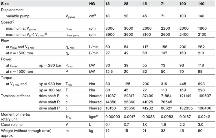
Table of values
(theoretical values, without considering efficiencies and tolerances; values rounded)Size NG 18 28 45 71 100 140
Displacement
variable pump Vg max cm3 18 28 45 71 100 140
Speed1)
maximum at Vg max nmax rpm 3300 3000 2600 2200 2000 1800
maximum at Vg < Vg max2) nmax perm. rpm 3900 3600 3100 2600 2400 2100
Flow
at nmax and Vg max qv max L/min 59 84 117 156 200 252
at n= 1500 rpm qv L/min 27 42 68 107 150 210
Power
at nmax Dp = 280 bar Pmax kW 30 39 55 73 93 118
at n= 1500 rpm P kW 12,6 20 32 50 70 98
Torque
at Vg max and Dp = 280 bar Tmax Nm 80 125 200 316 445 623
Dp = 100 bar T Nm 30 45 72 113 159 223
Torsional stiffness drive shaft S c Nm/rad 11087 22317 37499 71884 121142 169537
drive shaft R c Nm/rad 14850 26360 41025 76545 – –
drive shaft P c Nm/rad 13158 25656 41232 80627 132335 188406
Moment of inertia
rotary unit JTW kgm2 0.00093 0.0017 0.0033 0.0083 0.0167 0.0242
Case volume V L 0.4 0.7 1.0 1.6 2.2 3.0
Weight (without through drive) approx.
m kg 12 15 21 33 45 60
1) Values shown are valid for an absolute pressure (pabs) of 1 bar at inlet port S and use with mineral oil
(with a specific weight of 0,88kg/L).
2) Values are valid for Vg≤ Vg max or increase of inlet pressure p abs at inlet port S (see diagram page 5)
Note
Exceeding the maximum or falling below the minimum permissible values can lead to a loss of function, a reduction in operational service life or total destruction of the axial piston unit. The permissible values can be determined through calculation.
Determination of size
Flow qV =
Vg • n • hV
[L/min] Vg = Geometr. displacement per revolution in cm3
1000 Dp = Pressure differential in bar
Torque T = Vg • Dp [Nm] n = Speed in rpm
20 • p • hmh hV = Volumetric efficiency
Power P = 2p • T • n = qV • Dp [kW] hmh = Mechanical-hydraulic efficiency
60000 600 • ht ht = Overall efficiency (ht = hV • hmh)
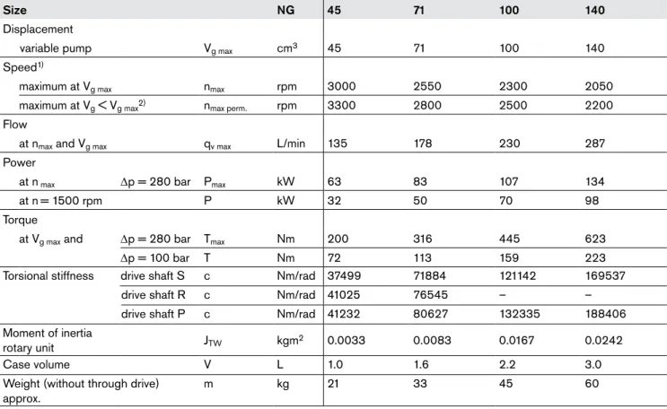
Table of values
(theoretical values, without considering efficiencies and tolerances; values rounded)Size NG 45 71 100 140
Displacement
variable pump Vg max cm3 45 71 100 140
Speed1)
maximum at Vg max nmax rpm 3000 2550 2300 2050
maximum at Vg < Vg max2) nmax perm. rpm 3300 2800 2500 2200
Flow
at nmax and Vg max qv max L/min 135 178 230 287
Power
at n max Dp = 280 bar Pmax kW 63 83 107 134
at n= 1500 rpm P kW 32 50 70 98
Torque
at Vg max and Dp = 280 bar Tmax Nm 200 316 445 623
Dp = 100 bar T Nm 72 113 159 223
Torsional stiffness drive shaft S c Nm/rad 37499 71884 121142 169537
drive shaft R c Nm/rad 41025 76545 – –
drive shaft P c Nm/rad 41232 80627 132335 188406
Moment of inertia
rotary unit JTW kgm2 0.0033 0.0083 0.0167 0.0242
Case volume V L 1.0 1.6 2.2 3.0
Weight (without through drive) approx.
m kg 21 33 45 60
1) Values shown are valid for an absolute pressure (pabs) of 1 bar at inlet port S and use with mineral oil
(with a specific weight of 0,88kg/L).
2) Don´t exceed the maximum flow (qv max).
The pump sizes 45, 71, 100 and 140 are optionally available in a in High-Speed version.
In comparison with the standard units, pumps in this version can be operated at higher input speeds without any change in outer dimensions.
Note
Exceeding the maximum or falling below the minimum permissible values can lead to a loss of function, a reduction in operational service life or total destruction of the axial piston unit. The permissible values can be determined through calculation.
Technical data
Permissible loading of drive shaft
Size NG 18 28 45 71 100 140
Max. radial load. at
X/2 Fq max N 350 1200 1500 1900 2300 2800
Max. axial load. Fax N 700 1000 1500 2400 4000 4800
Fq
X X/2 X/2
± Fax
Permissible input and through drive torques
Size NG 18 28 45 71 100 140
Torque, max.
(at Vg max and Dp = 280 bar1))
Tmax Nm 80 125 200 316 445 623
Max. permissible input torque2)
at drive shaft S to TE perm Nm 124 198 319 626 1104 1620
SAE J744 (ANSI B92.1a-1976) in 3/4 7/8 1 1 1/4 1 1/2 1 3/4
at drive shaft R similar to TE perm Nm 160 250 400 644 – –
SAE J744 (ANSI B92.1a-1976) in 3/4 7/8 1 1 1/4 – –
at drive shaft P TE perm Nm 88 137 200 439 857 1206
DIN 6885 mm 18j6 22j6 25j6 32j6 40k6 45k6
Max. through drive torque.
at drive shaft S TD perm Nm 108 160 319 492 778 1266
at drive shaft R TD perm Nm 120 176 365 548 – –
at drive shaft P TD perm Nm 88 137 200 439 778 1206
1) Without considering efficiencies 2) For drive shaft free of radial load
Distribution of torques
2. Pumpe
1. Pumpe
T
ET
DT
1T
2 1. Pumpe 2. Pumpe60 80 100 120 140 160 180 200 220 240 260 40 20 0 30 40 50 60 70 80 90 100 110 120 130 20 10 0 0 50 100 150 200 250 280 60 80 100 120 140 160 180 200 40 20 0 30 40 50 60 70 80 90 100 20 10 0 0 50 100 150 200 250 280
Characteristics for pumps with pressure control
Drive power and flow
(Operating fluid: hydraulic fluid to ISO VG 46 DIN 51519, t = 50°C)
60 40 20 0 30 20 10 0 0 50 100 150 200 250 280 Size 18 n = 1500 rpm n = 3300 rpm Size 100 n = 1500 rpm n = 2000 rpm Size 140 n = 1500 rpm n = 1800 rpm Size 28 n = 1500 rpm n = 3000 rpm Size 45 n = 1500 rpm n = 2600 rpm Size 71 n = 1500 rpm n = 2200 rpm 60 80 90 40 20 0 30 40 20 10 0 0 50 100 150 200 250 280 60 80 100 110 40 20 0 30 40 50 60 20 10 0 0 50 100 150 200 250 280 60 80 100 120 140 160 40 20 0 30 40 50 60 70 80 20 10 0 0 50 100 150 200 250 280
Operating pressure p [bar]
Operating pressure p [bar]
Operating pressure p [bar]
qv qv qv qv qv qv Pqv max Pqv max Pqv max Pqv max Pqv max Pqv max Pqv Null Pqv Null Pqv Null Pqv Null Pqv Null Pqv Null
Operating pressure p [bar]
Operating pressure p [bar]
Operating pressure p [bar]
Flow q V [ L/min ] Flow q V [ L/min ] Flow q V [ L/min ] Flow q V [ L/min ] Flow q V [ L/min ] Flow q V [ L/min ] Drive power P [ kW] Drive power P [ kW] Drive power P [ kW] Drive power P [kW] Drive power P [ kW] Drive power P [ kW]
DG – two-point control, directly operated
The pump can be set to a minimum swivel angle by connecting an external control pressure to port X.
This will supply control fluid directly to the stroking piston; a minimum pressure of pst≥ 50 bar is required.
The pump can only be switched between Vg max or Vg min.
Please note, that the required control pressure at port X is directly dependent on the actual operating pressure pB in port
B. (see switching pressure diagram). Control pressure pst in X = 0 bar Vg max
Control pressure pst in X ≥ 50 bar Vg min
The max. permissible switching pressure pst = 120 bar.
Switching pressure diagram
Ports
B Outlet port
S Inlet port
L, L1 Case drain port (L1 plugged)
X Control pressure port (plugged)
X L B S L1 0 50 70 140 210 280 120 100 50 Req . control pressure pst [ bar ]
Operating pressure pB [bar]
DR – Pressure control
Ports
B Outlet port
S Inlet port
L, L1 Case drain port (L1 plugged)
Controller data
Hysteresis and repetititive accuracy Dp__________ max. 3 bar
Pressure rise, max
Size 18 28 45 71 100 140
Dp bar 4 4 6 8 10 12
Pilot fluid consumption _______________max. approx. 3 L/min Flow loss at qVmax see page 9.
The DR-pressure control limits the maximum pressure at the pump outlet within the pump‘s control range. The pump therefore supplies only the amount of fluid as required by the actuators. This maximum pressure level can be set steplessly at the control valve.
Static characteristic (at n1 = 1500 rpm; tfluid = 50°C) 35 280 Flow qv [L/min] Operating pressure p B [ bar ]
Hysteresis and pressure rise
D pmax Setting range
L
B
S
L
1 Schematic DR size 18 to 100 Size 140The DR-pressure control (see page 11) is overriding this DRG-remote setting of max. outlet pressure.
A pressure relief valve can be externally piped to port X for remote setting of pressure below the setting of the DR control valve spool. This relief valve is not included in the pump supply. The differential pressure at the DRG-control spool is set as standard to 20 bar. This results in a pilot fluid flow to the relief valve of approx. 1,5 L/min at port X. If another setting is required (range from 10 to 22 bar) please state in clear text. As a separate relief valve we can recommend:
DBDH 6 (hydraulic) to RE 25402 or
DBETR-SO 381 with orifice dia. 0,8 mm in P (electric) to
RE 29166.
The max. lenght of piping should not exceed 2 m.
Static characteristic
(at n1 = 1500 rpm; tfluid = 50°C)
Controller data
Hysteresis Dp ___________________________ maximum 3 bar Pressure rise maximum
Size 18 28 45 71 100 140
Dp bar 4 4 6 8 10 12
Pilot fluid consumption _________________ approx. 4,5 L/min Flow loss at qv max see page 9.
20 280
DRG – Pressure control, remote
Flow qv [L/min] qv min qv max Operating pressure p B [ bar ]
Hysteresis and pressure rise
D pmax Setting range L B S L1 X Schematic DRG size 18 to 100 Ports B Outlet port S Inlet port
L, L1 Case drain port (L1 plugged)
X Pilot pressure port
Details of pilot pressure port X
Size 18 to 100 with adapter
Size 140 without adapter
not in scope of supply
not in scope of supply
Size 140
X
B
In additon to the pressure control function, the pump flow may be varied by means of a differential pressure over an orifice or valve spool installed in the service line to the actuator. The pump flow is equal to the actual required flow by the actuator, regardless of changing pressure levels.
The pressure control overrides the flow control function.
Note
The DFR1-valve version has no connection between X and the tank (pump housing).
Unloading the LS-pilot line must be possible in the valve system.
Because of the flushing function sufficient unloading of the X-line must also be provided.
Static characteristic
Flow controller at n1 = 1500 rpm; tfluid = 50°C)
Static characteristic at variable speed
DFR/DFR1 – Pressure and flow control
Ports
B Outlet port
S Inlet port
L, L1 Case drain port (L1 plugged)
X Pilot pressure port
Details of pilot pressure port X
Size 18 to 100 with adapter
Size 140 without adapter
Differential pressure Dp:
Standard setting: 14 bar. If another setting is required, please state in clear text.
Unloading port X to tank (with outlet port B closed) results in a zero stroke (standby) pressure of p = 18 ± 2 bar (dependent on the Dp setting).
Controller data
Data pressure control DR see page 11.
Maximum flow deviation measured with drive speed n = 1500 rpm.
Size 18 28 45 71 100 140
Dqv max L/min 0,9 1,0 1,8 2,8 4,0 6,0
Pilot flow consumption DFR max. approx. 3...4,5 L/min Pilot flow consumption DFR1 max. approx. 3 L/min
35
280
Flow qv [L/min] Flow q v [ L/min ] qv min qv max Operating pressure p B [ bar ] Dqv see table D qv see t able Setting range Speed n [rpm] X L B S L1 Schematic DFR size 18 to 100 closed in DFR1 valve closed in DFR1 valve not in scope of supply not in scope of supply Size 140In order to achieve a constant drive torque with varying opera-ting pressures, the swivel angle and with it the output flow from the axial piston unit is varied so that the product of flow and pressure remains constant.
Flow control is possible below the power control curve.
Static characteristic
at 1500 min-1
The power characteristic is factory set, please state power requirements when ordering, eg. 20 kW at1500 rpm.
Controller data
Technical data of pressure control see page 11. Technical data of flow control see page 13.
Beginning of control _______up to 50 bar and above 240 bar Pilot fluid consumption _____________ max. approx. 5,5 L/min Flow loss at qv max see page 9.
0 100 0 50 100 150 200 250 280 300 0 100 ∆qV Schematic DFLR size 28 to 100 not in scope of supply
DFLR – Pressure/flow/power control
X
L
B
S
L
1 not in scope of supply Size 140 X L B S L1 Ports B Outlet port S Inlet portL, L1 Case drain port (L1 plugged)
X Pilot pressure port Maximum power curve Minimum power curve Operating pressure p [ bar ] Torque T [ Nm ] Flow qv [%]
18 20 40 60 80 100 12 6 35 280 Schematic FHD size 28 to 100
FHD-displacement control,
pilot pressure dependent with pressure control
Size 140
Ports
B Outlet port
S Inlet port
L, L1 Case drain port (L1 plugged)
Mst Gauging port pilot support pressure (plugged) Y Pilot support pressure
X Pilot pressure port The swivel angle of the pump and hence the displacement or
flow, is dependent on the pilot pressure pSt X in port X.
A constant pressure pY = 35 bar is required at port Y. An
overriding pressure control is integrated and can be steplessly set at the control valve.
Please indicate setting values in clear text.
Controller data
Hysteresis ± 2 % of Vg max
External pilot fluid consumption
in Y _________________________ max. approx. 3 to 4,5 L/min Pressure rise Dp_____________________________ max. 4 bar Minimum system pressure pmin _____________________18 bar
Flow loss at qv max see page 9.
Static characteristic
(at n1 = 1500 rpm; tfluid = 50° C)
Hysteresis and pressure rise Dp
Displacement V/Vg
g max
[%]
Pilot pressure pSt X [bar]
Operating pressure p [bar] Setting range
Y
M
StX
L
B
S
L
1 Y MSt X L B S L1195 63 63 W V 145 X L L1 108 43 Ø8 0h8 6.3 83 11.5 52.4 26.2 S S Ø25 47 .6 Ø20 B B 22.2 L 126 40 152 66 11 109 max . 1 10 64 69 109 45° 45° X
Dimensions, size 18
Before finalising your design please request acertified installation drawing. Dimensions in mm
Flange ISO 3019-2 80-2
Valve mounting for counter clockwise rotation
DFR/DFR1
Pressure/flow control; clockwise rotation
View V View W
Ports
Designation Port for Standard Size 1) Peak pressure
[bar] 2) State
B Service line (standard pressure range)
Fixing thread SAE J518 DIN 13 3/4 in M10; 17 deep 350 O
S Suction (standard pressure range)
Fixing thread SAE J518 DIN 13 1 in M10; 17 deep 5 O
L Case drain DIN 3852 M16x1,5 2 O 3)
L1 Case drain DIN 3852 M16x1,5 2 plugged 3)
X Pilot pressure DIN 3852 M14x1,5; 12 deep 350 O
X Control press. for DG control DIN 3852 G 1/4 in 120 O
1) For the max. tightening torques the instructions on page 40 must be observed.
2) Application dependent pressure spikes can occur.. Please consider this when selecting measuring equipment or fittings 3) Dependent on the installation position, port L or L1 must be connected
3 G 1/ 4 in 25 +0.4 8912 97 X 148
126
max
. 1
10
X X108
126
40
109
max
. 1
10
XDimensions size 18
S Splined shaft 3/4 in 11T 16/32 DP1) SAE J744 - 19-4 (A-B) P Keyed shaft R Splined shaft 3/4 in 11T 16/32 DP1) SAE J744 - 19-4 (A-B)Before finalising your design please request a certified installation drawing. Dimensions in mm
Valve mounting for counter clockwise rotation
Valve mounting for counter clockwise rotation
Valve mounting for counter clockwise rotation
Drive shafts
DRG
pressure control, remote to mounting flange face
to mounting flange face
DR
pressure control
DG
Two point control, directly operated
38 30 22 14 1/ 4-20U N C -2B Ø3 /4in 14 21 38 ø3 /4 in 1/ 4-20U N C -2B 36 28 2 25 Ø1 8j6
For details of hydraulic connections see page 16
Centering 2)
R 3.15 x 6.7 DIN 332
1) ANSI B92.1a-1976, 30° pressure angle, flat base, flank centering, fit class 5 2) Axial retention of coupling half eg. via clamp coupling or clamping bolt
usable spline lenght
X
S
58. 7 Ø32 30.2B
22.2 Ø20 47 .6 Ø1 00 h8 80 80 206 14 40 X L L L1 164 6.3 9.5 W V 90 118 136 119.3 74 83.5 140 164 max . 1 10 40 74 14 45° 45° Ø1 74 S BDimensions, size 28
S Splined shaft 7/8 in 13T 16/32 DP4) SAE J744 - 22-4 (B) R Splined shaft 7/8 in 13T 16/32 DP4) SAE J744 - 22-4 (B)Before finalising your design please request a certified installation drawing. Dimensions in mm
View V
View W
DFR/DFR1
Pressure/flow control; clockwise rotation
Drive shafts
41 33.1 25.1 16 1/ 4-20U N C -2B Ø7 /8 in 16 25 41 ø7 /8 in 1/ 4-20U N C -2Busable spline lenght
Valve mounting for counter clockwise rotation
Ports
Designation Port for Standard Size 1) Peak press.
[bar] 2) State
B Service line (standard pressure range)
Fixing thread SAE J518 DIN 13 3/4 in M10; 17 deep 350 O
S Inlet (standard pressure range
Fixing thread SAE J518 DIN 13 1 1/4 in M10; 17 deep 5 O
L, L1 Case drain (L1 plugged) DIN 3852 M18x1,5; 12 deep 2 O 3)
X Pilot pressure DIN 3852 M14x1,5; 12 deep 350 O
X Control pressure for DG control DIN 3852 G 1/4 in 120 O
Y Pilot support pressure DIN 3852 M14x1,5; 12 deep max. 35 O
MB Meassuring outlet pressure SAE 3852 G 1/4 in 350 plugged
Mst Measuring pilot support pressure DIN 3853/ISO 8434
DIN 3861
Tube dia.8 mm max 18 closed
1) For the max. tightening torques the instructions on page 40 must be observed.
2) Application dependent pressure spikes can occur.. Please consider this when selecting measuring equipment or fittings 3) Dependent on the installation position, port L or L1 must be connected
O = Must be connected (plugged on delivery)
P Keyed shaft 36 16 2 32 M6 Ø22 j6 46
4) ANSI B92.1a-1976, 30° pressure angle, flat base, flank centering, fit class 5
Flange ISO 3019-2 100-2
Dimensions, size 28
Before finalising your design please request a certified installation drawing. Dimensions in mmDRG
Pressure control, remote
DR
Pressure control
FHD
Displ. control, pilot press. dependent with pressure controlDG
Two point control, directly operated
DFLR
Pressure/flow/power controlX
136
max
. 1
10
X 118 136 119 max . 1 10 40 135.5 119 max .11 0 40 198 Xto mounting flange face to mounting flange face
136 119 158 47 86 48 118 49 169 Mst Y 13 7. 5 124 X Mst MB 40 max . 1 10 L 3 G 1/ 4 in 25 +0.4 99.5 103.5 12 X 158
Valve mounting for counter clockwise rotation
Valve mounting for counter clockwise rotation
Valve mounting for counter clockwise rotation
Valve mounting for counter clockwise rotation
Valve mounting for counter clockwise rotation
W
V
X 35.7 Ø40 69.9S
B
Ø25 52. 4 26.2 129 146 133 90 90 max . 1 10 40 140 9.5L
L
X
L1
Ø1 00 h8 219 224 184 96 6.3 184 45 14.3 80.5 93.5 14 83 45° 45°Dimensions, size 45
S Splined shaft 1 in 15T 16/32 DP4)SAE J744 - 25-4 (B-B) R Splined shaft 1 in 15T 16/32 DP
4)
SAE J744 - 25-4 (B-B)
Before finalising your design please request a certified installation drawing. Dimensions in mm
DFR/DFR1
Pressure/flow control; clockwise rotation
Drive shafts
45.9 38 30 16 1/ 4-20U N C -2B Ø1 in 16 29.5 45.9 ø1in 1/4-20U N C -2B usable spline lenght View V View WValve mounting for counter clockwise rotation
Ports
Designation Port for Standard Size 1) Peak press.
[bar] 2) State
B Service line (standard pressure range)
Fixing thread SAE J518 DIN 13 1 in M10; 17 deep 350 O
S Inlet (standard pressure range)
Fixing thread SAE J518 DIN 13 1 1/2 in M12; 20 deep 5 O
L Case drain DIN 3852 M22x1,5 2 O 3)
L1 Case drain DIN 3852 M22x1,5 2 plugged 3)
X Pilot pressure DIN 3852 M14x1,5; 12 deep 350 O
X Control pressure for DG control DIN 3852 G 1/4 in 120 O
Y Pilot support pressure DIN 3852 M14x1,5; 12 deep max. 35 O
MB Measuring outlet pressure SAE 3852 G 1/4 in 350 plugged
Mst Measuring pilot support pressure DIN 3853/ISO 8434
DIN 3861 Tube dia. 8 mm max. 18 closed
1) For the max. tightening torques the instructions on page 40 must be observed.
2) Application dependent pressure spikes can occur.. Please consider this when selecting measuring equipment or fittings 3) Dependent on the installation position, port L or L1 must be connected
O = Must be connected (plugged on delivery)
P Keyed shaft 42 19 3 36 M8 Ø25 j6 52 4) ANSI B92.1a-1976, 30° pressure angle, flat base, flank centering, fit class 5
Flange ISO 3019-2 100-2
G
1/
4 in
25
+0.4173
110
117
X
3
12
Z 34 91 .5 134 146 129 174 MB MB B Y Mst 49 40 11 2 13 7 X X 187 30 55Dimensions, size 45
DRG
Pressure control, remote
DR
Pressure control
FHD
Displ. control, pilot press. dependent with press. controlDG
Two point control, directly operated
DFLR
Pressure/flow/power controlBefore finalising your design please request a certified installation drawing. Dimensions in mm
X
129
146
133
max
. 1
10
40
X
to mounting flange face to mounting flange face
View Z X
146
max
. 1
10
40 129X
11 2 213 146Valve mounting for counter clockwise rotation
Valve mounting for counter clockwise rotation
Valve mounting for counter clockwise rotation
Valve mounting for counter clockwise rotation
Valve mounting for counter clokwise rotation
L 77 .8 Ø50 S 42.9 Ø25 52.4 26.2 B 257 V W 92 max . 1 10 143 107.5 160 40 5318 Ø1 25 h8 18 98 180 210 L1 L 10 4 10 4 161 6 115 12.7 45° 45° X 217 X
Dimensions , size 71
Before finalising your design please request acertified installation drawing. Dimensionsin mm
DFR/DFR1
Pressure/flow control, port plate 42; clockwise rotation
View V
View W
Valve mounting for counter clockwise rotation
Ports
Designation Port for Standard Size 1) Peak press.
[bar] 2)
State
B Service line (Standard pressure range)
Fixing thread SAE J518 DIN 13 1 in M10; 17 deep 350 O
S Inlet (standard pressure range)
Fixing thread SAE J518 DIN 13 2 in M12; 20 deep 5 O
L Case drain DIN 3852 M22x1,5 2 O 3)
L1 Case draint DIN 3852 M22x1,5 2 plugged 3)
X Pilot pressure DIN 3852 M14x1,5; 12deep 350 O
X Control pressure for DG control DIN 3852 G 1/4 in 120 O
Y Pilot support pressure DIN 3852 M14x1,5; 12 deep max. 35 O
MB Measuring outlet pressure SAE 3852 G 1/4 in 350 plugged
Mst Measuring pilot support pressure DIN 3853/ISO 8434
DIN 3861
Tube dia. 8 mm max. 18 closed
1) For the max. tightening torques the instructions on page 40 must be observed.
2) Application dependent pressure spikes can occur.. Please consider this when selecting measuring equipment or fittings 3) Dependent on the installation position, port L or L1 must be connected
O = Must be connected (plugged on delivery)
S Splined shaft 1 1/4 in 14T 12/24 DP4)
SAE J744 - 32-4 (C) R Splined shaft 1 1/4 in 14T 12/24 DP
4) SAEJ744 - 32-4 (C)
Drive shafts
55.4 47.5 39.5 19 5/ 16-1 8U N C -2B Ø1 1/ 4in 19 38 55.4 ø1 1 /4in 5/ 16-1 8U N C -2Busable spline lenght
P Keyed shaft 50 22 2.5 45 M1 0 Ø32 j6 60
4) ANSI B92.1a-1976, 30° pressure angle, flat base, flank centering, fit class 5
Flange ISO 3019-2 125-2
L
77
.8
Ø50
S
42.9
Ø25
SAE 1in
(SAE 1 1/4in)
52.4
26.2
B
257
217
V
W
L
10
4
10
4
X
58.
7
30.2
Dimensions, size 71
Before finalising your design please request acertified installation drawing. Dimensions in mm
DFR/DFR1
Pressure/flow control, port plate 12
not for new applications
View VView W
Ports
Designation Port for Standard Size 1) Peak press.
[bar] 2)
State
B Service line (standard pressure range)
Fixing thread SAE J518 DIN 13 1 in (+ 1 1/4 in) M10; 17 deep 350 (250) O
S Inlet (standard pressure range
Fixing thread SAE J518 DIN 13 2 in M12; 20 deep 5 O
L Case drain DIN 3852 M22x1,5 2 O 3)
L1 Case drain DIN 3852 M22x1,5 2 plugged 3)
X Pilot pressure DIN 3852 M14x1,5; 12 deep 350 O
X Control pressure for DG control DIN 3852 G 1/4 in 120 O
Y Pilot support pressure DIN 3852 M14x1,5; 12 deep max. 35 O
MB Measuring outlet pressure SAE 3852 G 1/4 in 350 plugged
Mst Measuring pilot support pressure DIN 3853/ISO 8434
DIN 3861
Tube dia. 8 mm max. 18 closed
1) For the max. tightening torques the instructions on page 40 must be observed.
2) Application dependent pressure spikes can occur.. Please consider this when selecting measuring equipment or fittings 3) Dependent on the installation position, port L or L1 must be connected
O = Must be connected (plugged on delivery)
Note
At pressure port „B“ there are two SAE flanged ports available, each offset by 90°.
SAE 1 1/4 inch, standard pressure range, 3000 psi, for
pressures up to 250 bar.
SAE 1 inch, standard pressure range, 5000 psi, for
pressures up to 350 bar.
For operating pressures above 250 bar the standard pressure SAE 1 inch port must be used.
Dimensions, size 71
DRG
Pressure control, remote, port plate (12) 42
DR
Pressure control, port plate (12) 42
DG
Two point control, directly operated, port plate (12) 42
Before finalising your design please request a certified installation drawing. Dimensions in mm
L 110 max 143 160 40 161
X
Xto mounting flange face to mounting flange face
L 110 max 160 X L 201 12 3 G 1/ 4in 25 +0.4 127.5 123.5 X Valve mounting for counter clockwise rotation
Valve mounting for counter clockwise rotation
Valve mounting for counter clockwise rotation
FHD
Displacement control, pilot press. dependent with press. control; port plate (12) 42
DFLR
Pressure/flow/power control port plate (12) 42
L 242 143 159.5 12 4 X 40 L 103.5 30 143 148 160 161 MB 201 13 7. 5 12 4 Y Mst 49 69 40 69 218 X Mst
Valve mounting for coun-ter clockwise rotation
Valve mounting for counter clockwise rotation
X Ø32 66 .7 31.8 B S 88.9 Ø6 0 50.8 40 148.4 164.9 317 329 10 0 10 0 180 210 118 17 .5 15 2 106 95 W V X L L1 6 229 20 95 275 175 12.7 max . 1 10 Ø1 25 h8 45°
Dimensions, size 100
Before finalising your design please request acertified installation drawing. Dimensions in mm
DFR/DFR1
Pressure/flow control; clockwise rotation
View V
View W
Valve mounting for counter clockwise rotation S Splined shaft 1 1/2 in 17T 12/24 DP4) SAE J744 - 38-4 (C-C)
Drive shafts
61.9 54 43.6 28 7/ 16-1 4U N C -2B Ø1 1 /2in P Keyed shaftPorts
Designation Port for Standard Size 1) Peak press.
[bar] 2) State
B Service line (high pressure range)
Fixing thread SAE J518 DIN 13 1 1/4 in M14; 19 deep 350 O
S Inlet (standard pressure range
Fixing thread SAE J518 DIN 13 2 1/2 in M12; 17 deep 5 O
L Case drain DIN 3852 M27x2 2 O 3)
L1 Case drain DIN 3852 M27x2 2 plugged 3)
X Pilot pressure DIN 3852 M14x1,5; 12 deep 350 O
X Control pressure for DG control DIN 3852 G 1/4 in 120 O
Y Pilot support pressure DIN 3852 M14x1,5; 12 deep max. 35 O
MB Measuring outlet pressure SAE 3852 G 1/4 in 350 plugged
Mst Measuring pilot support pressure DIN 3853/ISO 8434
DIN 3861 Tube dia. 8 mm max. 18 closed
1) For the max. tightening torques the instructions on page 40 must be observed.
2) Application dependent pressure spikes can occur.. Please consider this when selecting measuring equipment or fittings 3) Dependent on the installation position, port L or L1 must be connected
O = Must be connected (plugged on delivery)
66 28 1.5 68 M1 2 Ø40 j6 80
4) ANSI B92.1a-1976, 30° pressure angle, flat base, flank centering, fit class 5
Flange ISO 3019-2 125-2
Dimensions, size 100
Before finalising your design please request a certified installation drawing. Dimensions in mmDRG
Pressure control, remote
DR
Pressure control
DG
Two point control, directly operated
to mounting flange face to mounting flange face
X
40
148
165
X
228
max
. 1
10
X165
max
. 1
10
268 12 25 +0.4 R 1/ 4in 3 128.5 132.5 XValve mounting for coun-ter clockwise rotation
Valve mounting for counter clockwise rotation
Valve mounting for coun-ter clockwise rotation
FHD
Displ. control, pilot press. dependent, with press. control
DFLR
Pressure/flow/power control148
40
164.5
12
9
17
.5
15
2
X
308
275 275 86 MST MB X 228 268 12 9 10 8.5 49 148 165 153 40 12 9Valve mounting for counter clockwise rotation
Valve mounting for counter clockwise rotation
L
88.9
66
.7
S
B
Ø32
31.8
Ø63
50.8
11
0
11
0
275
158.4
20
0
131
20.6
Y
V
W
45°
21
78
Ø1
80
h8X
L
1L
L
337
244
11
8.5
12
6
183
209
11
2
26
10
8
158.4
200
173
12.7
6.4
Dimensions, size 140
Before finalising your design please request acertified installation drawing. Dimensions in mm
DFR/DFR1
Pressure/flow control; clockwise rotation
View V
View W
View Y Name plate
Valve mounting for counter clockwise rotation S Splined shaft 1 3/4 in 13T 8/16 DP1) SAE J744 - 44-4 (D)
Drive shafts
75 67 53 32 1/2-1 3U N C -2B Ø1 3 /4inPorts
Designation Port for Standard Size 1) Peak pressure
[bar] 2) State
B Service line (high pressure range)
Fixing thread SAE J518 DIN 13 1 1/4 in M14; 19 deep 350 O
S Inlet (standard pressure range)
Fixing thread SAE J518 DIN 13 2 1/2 in M12; 17 deep 5 O
L Case drain DIN 3852 M27x2 2 O 3)
L1 Case drain DIN 3852 M27x2 2 plugged 3)
X Pilot pressure DIN 3852 M14x1,5; 12 deep 350 O
X Pilot pressure for DG control DIN 3852 M14x1,5; 12 deep 120 O
MH Measuring high pressure DIN 3852 M14x1,5; 12 deep 350 plugged
Y Pilot support pressure DIN 3852 M14x1,5; 12 deep max. 35 O
Mst Measuring pilot support pressure DIN 3853/ISO 8434
DIN 3861 Tube dia. 8 mm max. 18 closed
1) For the max. tightening torques the instructions on page 40 must be observed.
2) Application dependent pressure spikes can occur.. Please consider this when selecting measuring equipment or fittings 3) Dependent on the installation position, port L or L1 must be connected
O = Must be connected ( closed with protective covers on delivery)
P Keyed shaft 77 36 1.5 80 M1 6 Ø45 j6 92
4) ANSI B92.1a-1976, 30° pressure angle, flat base, flank centering, fit class 5
Flange ISO 3019-2 180-4
Dimensions, size 140
Before finalising your design please request a certified installation drawing. Dimensions in mmL 10 8 11 2 28 153 12 158 MH X 2.6 268
DRG
Pressure control, remote
DR
Pressure control
DG
Two point control, directly operated to mounting flange face
to mounting flange face L
170
26 1
26
Valve mounting for counter clockwise rotation
Valve mounting for counter clockwise rotation L 12 6 56 292 X 170 144 Valve mounting for counter
clockwise rotation L 49 11 9 15 0 13 9 184 210 26 X 99 Mst Y 244 268
FHD
Displ. control, pilot press. dependent with press. control
DFLR
Pressure/flow/power control
Valve mounting for counter clockwise rotation
Valve mounting for counter clockwise rotation L 13 9.5 X 314 10 8 56 183 209
A4 10 ø101. 6 +0.050 +0.020 A5 ø146 A B 45° A3 A2 A1 A5
B
45° ø106.5A
A4 10 ø82.55 +0.050 +0.020 A3 A2 A1Through drive dimensions
K01 Flange SAE J744 - 82-2 (A)
coupler for splined shaft to ANSI B92.1a-1976 5/8in 9T 16/32 DP1) (SAE J744 - 16-4 (A))
K52 Flange SAE J744 - 82-2 (A)
coupler for splined shaft to ANSI B92.1a-1976 3/4in 11T 16/32 DP1) (SAE J744 - 19-4 (A-B))
K68 Flange SAE J744 - 101-2 (B)
coupler for splined shaft to ANSI B92.1a-1976 7/8in 13T 16/32 DP1) (SAE J744 - 22-4 (B))
Size A1 A4 A5 18 182 42 M10; 14 deep 28 204 47 M10; 14,5 deep 45 229 53 M10; 14,5 deep 71 267 61 M10; 17 deep 100 338 65 M10; 17 deep 140 350 77 M10; 17 deep Size A1 A2 A3 A4 A5 18 182 39 17,5 43 M10; 14,5 deep 28 204 39 17,5 47 M10; 16 deep 45 229 39 17,5 53 M10; 16 deep 71 267 39 17,5 61 M10; 20 deep 100 338 39 17,5 65 M10; 20 deep 140 350 39 17,5 77 M10; 17 deep Size A1 A2 A3 A4 A5 28 204 42 16,5 47 M12; through bore 45 229 42 16,5 53 M12; 18 deep 71 267 42 16,5 61 M12; 20 deep 100 338 42 16,5 65 M12; 20 deep 140 350 42 16,5 77 M12; 20 deep A4 A1 9 10 ø82.55 +0.050 +0.020 A5
B
45° ø106.5A
to mounting flange face
to mounting flange face
to mounting flange face
Before finalising your design please request a certified installation drawing. Dimensionsin mm
omitted on size 28 omitted on
size 28
A5 A B 45° ø181 A4 A3 A1 13 ø127 +0.050 +0.020 13 B 45° ø181 ø127 +0.050 +0.020 A3 A A2 A4 A1 A2 B 45° ø146 A3 10 ø101.6 +0.050 +0.020 A A4 A1
Through drive dimensions
K04 Flange SAE J744 - 101-2 (B)coupler for splined shaft to ANSI B92.1a-1976 1in 15T 16/32 DP1) (SAE J744 - 25-4 (B-B))
K07 Flange SAE J744 - 127-2 (C)
coupler for splined shaft to ANSI B92.1a-1976 1 1/4in 14T 12/24 DP1) (SAE J744 - 32-4 (C))
K24 Flange SAE J744 - 127-2 (C)
coupler for splined shaft to ANSI B92.1a-1976 1 1/2in 17T 12/24 DP1) (SAE J744 - 38-4 (C-C))
Size A1 A2 A3 A4 A5 71 267 56,5 17,9 61 M16; through bore 100 338 56,5 17,9 65 M16; through bore 140 350 56,5 17,9 77 M16; 24 deep Size A1 A3 A4 A2 45 229 18 47 M12; 18 deep 71 267 18 47 M12; 20 deep 100 338 18 47 M12; 20 deep 140 350 18 47 M12; 20 deep Size A1 A3 A4 A5 100 338 8 65 M16; through bore 140 350 8 77 M16; 24 deep
to mounting flange face
to mounting flange face
omitted on size 71 omitted on size 71
to mounting flange face
Before finalising your design please request a certified installation drawing. Dimensions in mm
13 ø152. 4 +0.07 +0.02 161.6 161.6 A B A5 A4 A3 A1 A2 A3 A1 9 ø63 H7 M8 45° B A 28. 3 +0. 2 ø80 8JS8 ø25H7
Through drive dimensions
K17 Flange SAE J744 - 152-4 (D)coupler for splined shaft to ANSI B92.1a-1976 1 3/4in 13T 8/16 DP1) (SAE J744 - 44-4 (D))
K57 Metric 4-bolt flange for mounting a radial piston pump R4 (see RE 11263) coupler for metric keyed shaft
Size A1 A3 A4 A5
140 350 8 77 M16;
through bore
to mounting flange face
to mounting flange face
Before finalising your design please request a certified installation drawing. Dimensions in mm
Size A1 A2 A3 28 232 75 9 45 257 81 9 71 283 77 9 100 354 81 9 140 366 93 9
A
B
10 Ø1 00 +0.050 +0.020A
5A
2A
1A
3 45° Ø140A
B
10 Ø1 00 +0.050 +0.020A
5A
2A
1A
3 45° Ø140Through drive dimensions
Before finalising your design please request acertified installation drawing. Dimensions in mm KB2 Flange ISO 3019-2 - 80A2SW
coupler for splined shaft to ANSI B92.1a-1976 3/4in 11T 16/32 DP1) (SAE J744 - 19-4 (A-B))
KB3 Flange ISO 3019-2 - 100A2SW
coupler for splined shaft to ANSI B92.1a-1976 7/8in 13T 16/32 DP1) (SAE J744 - 22-4 (B))
KB4 Flange ISO 3019-2 - 100A2SW
coupler for splined shaft to ANSI B92.1a-1976 1in 15T 16/32 DP1) (SAE J744 - 25-4 (B-B))
Size A1 A2 A3 A5 28 204 42 16,5 M12; through bore 45 229 42 16,5 M12; through bore 71 267 42 16,5 M12; 20 deep 100 338 42 16,5 M12; 20 deep 140 350 42 16,5 M12; 20 deep Size A1 A2 A3 A5 45 229 47 18 M12; through bore 71 267 47 18 M12; 20 deep 100 338 47 18 M12; 20 deep 140 350 47 18 M12; 20 deep
A
B
10 Ø8 0 +0.050 +0.020A
5A
2A
4A
1A
3 45° Ø109to mounting flange face
to mounting flange face
to mounting flange face
1) 30° pressure angle, flat base, flank centering, fit class 5
Size A1 A2 A3 A4 A5 18 182 39 17,5 43 M10; 14,5 deep 28 204 39 17,5 47 M10; 16 deep 45 229 39 17,5 53 M10; 16 deep 71 267 39 17,5 61 M10; 20 deep 100 338 39 17,5 65 M10; 20 deep 140 350 39 17,5 77 M10; 17 deep
A
B
A
1A
5A
2A
3Ø1
80
+0.050 +0.02010
158.4
158.4
A
B
A
5A
1A
2A
3180
Ø1
25
+0.050 +0.02010
45°
Through drive dimensions
Before finalising your design please request acertified installation drawing. Dimensions in mm KB5 Flange ISO 3019-2 - 125A2SW
coupler for splined shaft to ANSI B92.1a-1976 1 1/4in 14T 12/24 DP1) (SAE J744 - 32-4 (C))
KB6 Flange ISO 3019-2 - 125A2SW
coupler for splined shaft to ANSI B92.1a-1976 1 1/2in 17T 12/24 DP1) (SAE J744 - 38-4 (C-C))
KB7 Flange ISO 3019-2 - 180B4HW
coupler for splined shaft to ANSI B92.1a-1976 1 3/4in 13T 8/16 DP1) (SAE J744 - 44-4 (D))
A
B
A
5A
1A
2A
3180
Ø1
25
+0.050 +0.02010
45°
to mounting flange face
to mounting flange face
to mounting flange face
Size A1 A2 A3 A5 71 267 56,5 17,9 M16; through bore 100 338 56,5 17,9 M16; through bore 140 350 56,5 17,9 M16; 24 deep Size A1 A2 A3 A5 100 338 65 8 M16; through bore 140 350 77 8 M16; 24 deep Size A1 A2 A3 A5 140 350 77 8 M16; through bore
omitted on size71 omitted on size71
Overview of attachements
SAE-mounting flange
Through drive - A10V(S)O Mounting option - 2. pump Through
drive availa-ble on size Flange
(SAE-J744) Coupler for splined shaft Code A10V(S)O/31 Size (shaft) A10V(S)O/52 (53) Size (shaft) Gear pump
82-2 (A) 16-4 (5/8 in) K01 18 (U) 10 (U) (18 (U)) Series F 18 to140
19-4 (3/4 in) K52 18 (S, R) 10 (S) (18 (S, R)) Series F 18 to140
101-2 (B) 22-4 (7/8 in) K68 28 (S, R) 28 (S, R) Series N, G 28 to 140 45 (U, W)1) 45 (U, W)1) 25-4 (1 in) K04 28 (S, R) 45 ( S, R) 28 to 100 45 (S, R) 63 (U, W)2) 127-2 (C) 32-4 (1 1/4 in) K07 71 (S, R) 85 (U, W)3) 71 to 140 100 (U)3) 38-4 (1 1/2 in) K24 100 (S) 85 (S) 100 to 140 152-4 (4-bolt D) 44-4 (1 3/4 in) K17 140 (S) 140
1) Not with K68-through drive on main pump size 28 2) Not with K04-through drive on main pump size 45 3) Not with K07-through drive on main pump size 71
ISO-mounting flange
Through drive - A10V(S)O Mounting option - 2. pump Through
drive availa-ble on size Flange
(ISO 3019-2 ) Coupler for splined shaft Code A10V(S)O/31 Size (shaft) A10V(S)O/52 (53) Size (shaft) Gear pump
ISO 80, 2-bolt 19-4 (3/4 in) KB2 18 (S, R) 10 (S) (18 (S, R)) 18 to 140
ISO 100, 2-bolt 22-4 (7/8 in) KB3 28 (S, R) 28 (S, R) Series N, G 28 to 140
25-4 (1 in) KB4 45 (S, R) 45 (S, R) 45 to 140
ISO 125, 2-bolt 32-4 (1 1/4 in) KB5 71 (S, R) 85 (S) 71 to 140
38-4 1 (1/2 in) KB6 100 (S) 100 to 140
ISO 180, 4-bolt 44-4 (1 3/4 in) KB7 140 (S) 140
Keyed shaft
Through drive - A10V(S)O Mounting option - 2. pump Through
drive availa-ble on size Coupler for Keyed shaft Code A10V(S)O/31 Size (shaft) A10V(S)O/52 (53) Size (shaft)
Radial piston pump
Combination pumps A10VSO + A10VSO
The use of combination pumps offers the possibility of inde-pendent pump circuits without the need for a splitter gearbox. When ordering combination pumps the designations for the 1. and the 2. pump must be joined by a „+“ sign.
Example:
A10VSO 100DR/31R-PSC12K07 + A10VSO 71DR/31R-PSC12N00
If a gear pump or a radial piston pump must be factory-moun-ted please consult us.
The A10V(S)O axial piston unit can be supplied with a through drive according to the ordering code on page 3. The through drive version is designated by the code numbers (K01-K24). If no other pumps are factory-mounted , the simple type designa-tion is sufficient.
The delivery of a pump with through drive includes the shaft coupler, the seal and if applicable an adapter flange. Every through drive is closed with a non protective cover upon delivery. Prior to start up this cover must be replaced by a pressure tight cover (or a 2nd pump).
Through drives can be ordered with a pressure tight cover. Please indicate in clear text.
Permissible moment of inertia
It is permissible to combine two single pumps of the same size (tandem pump) and operate the combination with a max. permissi-ble dynamic acceleration of 10g (98.1 m/s2) without additional support.
Size 18 28 45 71 100 140
Permissible moment of inertia
static Tm Nm 500 880 1370 2160 3000 4500 dynamic at 10g (98.1 m/s2) Tm Nm 50 88 137 216 300 450 Weight m kg 12 15 21 33 45 60 To center of gravity L1 mm 90 110 130 150 160 160 l1 l2 l3 m1 m2 m3 m1, m2, m3 Weight of pump [kg] l1, l2, l3 To center of gravity [mm] Tm = (m1• l1 + m2• l2 + m3• l3) • 1 [Nm] 102
General
The pump housing must be filled with fluid during commissioning and operation and must be deaerated. This must also be the case after prolonged periods of standstill since the system can empty itself through the hydraulic lines.
This is especially important with the mounting position „shaft end upwards or downwards“: make sure that the housing is com-pletely filled with fluid, to prevent the bearings and shaft seal from running dry and overheating.
Connect the highest one of the case drain ports with tubing of the light series wall thickness and the largest size corresponding to the port size. In order to attain the lowest noise level, all connections (suction, pressure, pilot, and case drain) must be linked by flexible members to tank and try to avoid mounting above the reservoir.
In case of combination pumps with different case drain pressures it is necessary that each pump has its own case drain line. In every operating condition the inlet and the case drain lines must always enter the reservoir below the minimum fluid level (ht min= 200 mm). The permissible suction height h depends on the overall suction pressure losses, but may never exceed
hSmax = 800 mm. The minimum inlet pressure at port S may not fall below the minimum value of pabs min = 0.8 bar under any static
or dynamic condition.
Installation position
See the following examples1 to 15. Recommended positions: 1 and 3. For more installation position please consult us.
Mounting below the reservoir (Standard)
This is the case whenever the pump is mounted below the min. fluid level. The pump can be installed next to or underneath the reservoir.
Mounting above reservoir
Installation above the reservoir means that the pump is mounted above the min. fluid level. The use of a check valve in the case drain line is only permissible in individual cases and only after consulting us.
Position Air bleed Filling
1, 3 and 5 F S + L, L1 (F)
2 and 4 F S + L, L1 (F)
Position Air bleed Filling
6, 8 and 10 F L, L1 (F) 7 and 9 F S + L, L1 (F)
Installation instructions
L L1 S ht min 200 mm ht min 200 mm SB SBmin. 200 mm min. 200 mm min. 200 mm min. 200 mm min. 200 mm
F 1 F L L1 S ht min 200 mm SB F 3 5 2 L L1 S ht min 200 mm SB F 4 L L1 S ht min 200 mm SB F L L1 S X h min 100 mm h min 100 mm h min 100 mm h min 100 mm h min 100 mm L L1 S F hs max 800 mm htmin 200 mm hs max 800 mm min. 200 mm SB SB S min. 200 mm min. 200 mm min. 200 mm F 6 7 L L1 L L1 S F hs max 800 mm h800 mms max SB SB S F 8 9 L L1 hs max 800 mm SB S min. 200 mm F 10 L L1 X
h min 100 mm hh tminmin 200 mm100 mm
htmin 200 mm htmin 200 mm
htmin
200 mm h min 100 mm h min 100 mm h min 100 mm
L/L1 = case drain port, F = air bleed- or. fill port, S = inlet port, SB = baffle plate, ht min = minimum permissible immersion depth,
Installation instructions
Inside the reservoir
Mounting inside the reservoir. This means that the pump is mounted within the fluid volume.
L L1 S ht min h min 100 mm
min. 200 mm min. 200 mm min. 200 mm min. 200 mm min. 200 mm
SB 11 L L1 S h t min SB 13 L L1 S h t min SB 12 L L1 S h t min SB 14 15 L L1 S h t min SB X h min 100 mm h min 100 mm h min 100 mm h min 100 mm
L/L1 = case drain port, F = air bleed or fill port, S = inlet port, SB = baffle plate, ht min = minimum permissible immersion depth,
ht max = maximum permissible suction height
Position Air bleed Filling
11, 13 and 15 L, L1 L, L1
© This document, as well as the data, specifications and other information set forth in it, are the exclusive property of Bosch Rexroth AG. It may not be reprodu-ced or given to third parties without its consent.
The data specified above only serve to describe the product. No statements concerning a certain condition or suitability for a certain application can be de-rived from our information. The information given does not release the user from the obligation of own judgment and verification. It must be remembered that our products are subject to a natural process of wear and aging.
Subject to change.
Bosch Rexroth AG Hydraulics Axial Piston Units An den Kelterwiesen 14 72160 Horb, Germany Telefon +49 (0) 74 51 92-0 Telefax +49 (0) 74 51 82 21 [email protected] www.boschrexroth.com/ics
General instructions
The pump A10VSO was designed for operation in open loop circuits –
Systems design, installation and commissioning requires trained technicians or tradesmen. –
All hydraulic ports can only be used for the fastening of hydraulic service lines. –
During and shortly after operation of a pump the housing and especially a solenoid can be extremely hot, avoid being burned; –
take suitable safety measures (wear protective clothing).
Dependent on the operating conditions of the axial piston pump (operating pressure, fluid temperature) deviations in the perfor-–
mance curves can occur. Pressure ports:
–
All materials and port threads are selected and designed in such a manner, that they can withstand the peak pressures. The machine and system manufacturer must ensure, that all connecting elements and hydraulic lines are suitable for the actual operating pressures.
Pressure cut off and pressure control are not suitable for providing system protection against excessive pressures. A suitable –
overall main line relief valve must be incorporated. All given data and information must be adhered to. –
The following tightening torques are valid: –
- Female threads in the axial piston unit:
the maximum permissible tightening torques MGMax are maximum values for the female threads in the pump casting and may
not be exceeded. Value see table below. - Fittings:
please comply with the manufacturer‘s information regarding the max. permissible tightening torques for the used fittings. - Fastening bolts:
for fastening bolts to DIN 13 we recommend to check the permissible tightening torques in each individual case to VDI 2230. - Plugs:
for the metal plugs, supplied with the axial piston unit the following min. required tightening torques MV apply (see table).
Thread size in ports Maximum permissible tightening torque M
G max
Min. required tightening
torque MV
Across the flats in Allan screw G1/4 in DIN 3852 70 Nm 7/8-14 UNF-2B ISO 11926 40 Nm 15 Nm 3/16 in 1 1/16-12 UNF-2B ISO 11926 360 Nm 147 Nm 9/16 in M14x1,5 DIN 3852 80 Nm 35 Nm 6 mm M16x1,5 DIN 3852 100 Nm 50 Nm 8 mm M18x1,5 DIN 3852 140 Nm 60 Nm 8 mm M22x1,5 DIN 3852 210 Nm 80 Nm 10 mm M27x2 DIN 3852 330 Nm 135 Nm 12 mm