© 2015-2016 Cisco and/or its affiliates. All rights reserved. This document is Cisco Public Information. Page 1 of 129
Design and Configuration Guide:
Best Practices for Virtual Port
Channels (vPC) on Cisco Nexus
7000 Series Switches
Revised: November 2015
© 2015-2016 Cisco and/or its affiliates. All rights reserved. This document is Cisco Public Information. Page 2 of 129
Contents
Introduction ... 4
vPC Description and Terminology ... 5
Benefits of vPC ... 5
NX-OS Version Requirement for vPC ... 6
NX-OS License Requirement for vPC ... 6
Components of vPC ... 7
vPC Data-Plane Loop Avoidance ... 8
vPC Deployment Scenarios ... 9
Single-Sided vPC ... 10
Double-Sided vPC ... 11
Multilayer vPC for Aggregation and DCI ... 12
Best Practices for Building a vPC Domain ... 14
Building a vPC Domain... 14
vPC Domain Identifier ... 15
vPC System-Mac and vPC Local System-Mac ... 16
Cisco Fabric Services (CFS) Protocol ... 21
Checking vPC Configuration Consistency When You Build a vPC Domain ... 23
Configuration Parameters That Must Be Identical (Type-1 Consistency Check) ... 23
Configuration Parameters That Should Be Identical (Type-2 Consistency Check) ... 26
Building a vPC Domain: Guidelines and Restrictions ... 27
Best Practices for vPC Components Configuration ... 28
Recommendation for vPC VLAN Configuration ... 28
Recommendations for vPC Peer-Keepalive Link Configuration ... 28
vPC Peer-Keepalive Link Using mgmt0 Cisco Nexus 7000 Series Pairs with Dual Supervisors Each . 30 vPC Peer-Keepalive Link and VRF ... 31
Recommendations for vPC Peer-Link Configuration... 31
vPC Systems Behavior When a vPC Peer-Link Goes Down ... 35
Recommendations for vPC Peer-Link Configuration with Systems Containing Only One M1 10-Gbps Module ... 36
vPC Object Tracking ... 36
Recommendations for vPC Member Port Configuration ... 38
Best Practices for vPC in Mixed Chassis Mode (M1/F1 Ports in Same System or VDC) ... 41
Layer 3 Internal Proxy Routing ... 41
vPC in Mixed Chassis Mode ... 42
vPC Mixed Chassis Mode with Peer-Link on F1 and Only One M1 Line Card ... 45
Best Practices for Attaching a Device to vPC Domain ... 46
How to Attach Devices to a vPC Domain ... 46
Access Device Dual-Attached to vPC Domain ... 47
Single-Sided vPC with 16-Way Port-Channel... 48
Double-Sided vPC with 32-Way Port-Channel ... 49
Access Device Single-Attached to vPC Domain ... 54
Best Practices for Data Center Interconnect and Encryption ... 58
Multilayer vPC for Aggregation and DCI ... 59
Dual Layer 2 /Layer 3 pod Interconnect ... 61
Best Practices for Spanning Tree Protocol Interoperability ... 62
About Spanning Tree Protocol Interoperability with vPC ... 62
© 2015-2016 Cisco and/or its affiliates. All rights reserved. This document is Cisco Public Information. Page 3 of 129
Recommended Spanning Tree Protocol Configuration with vPC ... 63
STP Interoperability with vPC - Blueprint Diagram ... 65
vPC and Spanning Tree Protocol Bridge Protocol Data Units ... 66
vPC Peer-Switch ... 67
Bridge Assurance and vPC ... 72
NX-OS and IOS Internal VLAN Range Allocation ... 73
Best Practices for Layer 3 and vPC... 74
About Layer 3 and vPC ... 74
Layer 3 and vPC: Guidelines and Restrictions ... 75
Layer 3 and vPC Interactions: Supported Designs ... 77
Layer 3 and vPC Interactions: Unsupported Designs ... 81
vPC and L3 Backup Routing Path ... 84
Best Practices for HSRP/VRRP and vPC ... 85
HSRP/VRRP active/active with vPC ... 85
HSRP/VRRP Guidelines and Restrictions ... 87
vPC and HSRP/VRRP Object Tracking ... 88
vPC and HSRP/VRRP in the Context of DCI ... 89
Best Practices for Network Services and vPC ... 93
Network Services Chassis with VDC Sandwich Design ... 93
Network Services Appliances in Transparent Mode with vPC ... 95
Configuring Cisco ASA Service Appliance in Transparent Mode with vPC ... 96
Network Services Appliances in Routed Mode with vPC ... 100
Configuring Cisco ASA Service Appliance in Routed Mode with vPC ... 102
Best Practices for Multicast and vPC... 106
Pre-building Shorted Path for Multicast with vPC (PIM pre-build-spt) ... 109
Best Practices for FEX and vPC ... 111
Best Practices for VDC and vPC ... 114
Best Practices for ISSU (In-Service Software Upgrade) with vPC ... 116
vPC System NX-OS Upgrade (or Downgrade) ... 117
vPC Enhancements ... 118
vPC Peer-Gateway ... 119
vPC Peer-Gateway Exclude-Vlan ... 120
vPC ARP Sync ... 121
vPC Delay Restore ... 121
vPC Graceful Type-1 Checks ... 122
vPC Auto-Recovery ... 123
vPC Orphan Ports Suspend ... 125
© 2015-2016 Cisco and/or its affiliates. All rights reserved. This document is Cisco Public Information. Page 4 of 129
Introduction
This guide provides best practices for using virtual Port Channels (vPCs) on Cisco Nexus® 7000 Series Switches.
Use this document in conjunction with the complete Cisco Nexus 7000 Series documentation, which you will find at: http://www.cisco.com/en/US/products/ps9402/tsd_products_support_series_home.html.
vPC user guide is located at the following link (CCO):
http://www.cisco.com/en/US/docs/switches/datacenter/sw/6_x/nx-os/interfaces/configuration/guide/if_vPC.html. (vPC user guide is contained within NX-OS interface configuration guide).
The best practices in this document follow a consistent pattern that makes the information in each section easy to find. Best practices for vPCs are organized in the following ways:
● vPC description and Terminology
● vPC deployment scenario
● Best Practices for Building a vPC Domain
● Best Practices for vPC Components Configuration
● Best practices for vPC in mixed chassis mode (M1/F1 ports in same system or VDC)
● Best practices for attaching a device to vPC domain
● Best practices for Data Center Interconnect and Encryption
● Best Practices for Spanning Tree Protocol Interoperability
● Best practices for Layer 3 and vPC
● Best practices for HSRP/VRRP and vPC
● Best practices for Network Services and vPC
● Best practices for Multicast and vPC
● Best practices for FEX and vPC
● Best practices for VDC and vPC
This document also covers ISSU operations related to vPC and give details about latest vPC enhancements (object-tracking, peer-gateway, peer-switch, reload restore, delay restore, graceful type-1 check, auto-recovery, orphan ports suspend, host vPC).
vPC scalability numbers are published at the following link (CCO):
http://www.cisco.com/en/US/docs/switches/datacenter/sw/verified_scalability/b_Cisco_Nexus_7000_Series_NX-OS_Verified_Scalability_Guide.html#reference_32EB4DB289634F6FA8885FDFD8E71F5F.
Take into consideration these scale numbers to design properly a network based on vPC technology.
Note: This document does not cover the following topic:
© 2015-2016 Cisco and/or its affiliates. All rights reserved. This document is Cisco Public Information. Page 5 of 129
vPC Description and Terminology
Benefits of vPC
vPC is a virtualization technology that presents both Cisco Nexus 7000 Series paired devices as a unique Layer 2 logical node to access layer devices or endpoints. vPC belongs to Multichassis EtherChannel [MCEC] family of technology.
A virtual port channel (vPC) allows links that are physically connected to two different Cisco Nexus 7000 Series devices to appear as a single port channel to a third device. The third device can be a switch, server, or any other networking device that supports link aggregation technology.
vPC provides the following technical benefits:
● Eliminates Spanning Tree Protocol (STP) blocked ports
● Uses all available uplink bandwidth
● Allows dual-homed servers to operate in active-active mode
● Provides fast convergence upon link or device failure
● Offers dual active/active default gateways for servers
vPC also leverages native split horizon/loop management provided by port-channeling technology: a packet entering a port-channel cannot immediately exit that same port-channel.
By using vPC, users get the immediate operational and architectural advantages:
● Simplifies network design
● Build highly resilient and robust Layer 2 network
● Enables seamless virtual machine mobility and server high-availability clusters
● Scales available Layer 2 bandwidth, increasing bisectional bandwith
● Grows the size of the Layer 2 network
Figure 1. Creating a Single Logical Node through vPC (virtual Port Channel) Technology
© 2015-2016 Cisco and/or its affiliates. All rights reserved. This document is Cisco Public Information. Page 6 of 129 ● vPC uses all port-channel member links available so that in case an individual link fails, hashing algorithm
will redirect all flows to the remaining links.
● vPC domain is composed of two peer devices. Each peer device processes half of the traffic coming from the access layer. In case a peer device fails, the other peer device will absorb all the traffic with minimal convergence time impact.
● Each peer device in the vPC domain runs its own control plane, and both devices work independently. Any potential control plane issues stay local to the peer device and does not propagate or impact the other peer device.
From a Spanning-Tree standpoint, vPC eliminates STP blocked ports and uses all available uplink bandwidth. Spanning-Tree is used as a fail safe mechanism and does not dictate L2 path for vPC-attached devices. Withing a vPC domain, user can connect access devices in multiple ways: vPC-attached connections leveraging active/active behavior with port-channel, active/standby connectivity using spanning-tree, single attachment without spanning-tree running on the access device.
All these connectivity configurations are fully supported and will be detailed in the following document.
NX-OS Version Requirement for vPC
vPC technology is supported since NX-OS 4.1.3. (i.e since the inception of NEXUS 7000 platform).
NX-OS appropriate version depends on line cards configuration (M1, F1 or F2), chassis type (7010, 7018 or 7009) and Fabric Module generation (FM generation 1 [46Gbps per module] or generation 2 [110Gbps per module]). Please refer to the following URL to check the recommended NX-OS version:
http://www.cisco.com/en/US/docs/switches/datacenter/sw/nx-os/recommended_releases/recommended_nx-os_releases.html.
[Minimum Recommended Cisco NX-OS Releases for Cisco Nexus 7000 Series Switches]. NX-OS release notes for each code release can be found at this location:
http://www.cisco.com/en/US/products/ps9402/prod_release_notes_list.html.
NX-OS License Requirement for vPC
vPC feature is included in the base NX-OS software license.
Hot Standby Router Protocol (HSRP), Virtual Router Redundancy Protocol (VRRP), Link Aggregation Control Protocol (LACP) are also included in this base license.
Layer 3 features like Open Shortest Path First (OSPF) protocol or Intermediate-System-to-Intermediate System (IS-IS) protocol require LAN_ENTERPRISE_SERVICES_PKG license.
© 2015-2016 Cisco and/or its affiliates. All rights reserved. This document is Cisco Public Information. Page 7 of 129
Components of vPC
Table 1 lists important terms you need to know to understand vPC technology. These terms are used throughout this guide.
Table 1. vPC Terms
Term Meaning
vPC The combined port-channel between the vPC peers and the downstream device. A vPC is a L2 port type: switchport mode trunk or switchport mode access
vPC peer device A vPC switch (one of a Cisco Nexus 7000 Series pair).
vPC domain Domain containing the 2 peer devices.
Only 2 peer devices max can be part of same vPC domain.
vPC member port One of a set of ports (that is, port-channels) that form a vPC (or port-channel member of a vPC).
vPC peer-link Link used to synchronize the state between vPC peer devices. It must be a 10-Gigabit Ethernet link. vPC peer-link is a L2 trunk carrying vPC VLAN.
vPC peer-keepalive link The keepalive link between vPC peer devices; this link is used to monitor the liveness of the peer device.
vPC VLAN VLAN carried over the vPC peer-link and used to communicate via vPC with a third device. As soon as a VLAN is defined on vPC peer-link, it becomes a vPC VLAN
non-vPC VLAN A VLAN that is not part of any vPC and not present on vPC peer-link.
Orphan port A port that belong to a single attached device. vPC VLAN is typically used on this port.
Cisco Fabric Services (CFS) protocol
Underlying protocol running on top of vPC peer-link providing reliable synchronization and consistency check mechanisms between the 2 peer devices.
© 2015-2016 Cisco and/or its affiliates. All rights reserved. This document is Cisco Public Information. Page 8 of 129
Figure 2. vPC Components
Best practices to build vPC peer-link and vPC peer-keepalive link will be described in the section “Best Practices for Building a vPC Domain”.
Recommendations to connect an orphan port to vPC domain will be described in the section “ Best practices for attaching a device to vPC domain”.
vPC Data-Plane Loop Avoidance
vPC performs loop avoidance at data-plane layer instead of control plane layer for Spanning Tree Protocol. All logics are implemented directly in hardware on vPC peer-link ports, avoiding any dependancy to CPU utilization. vPC peer devices always forward traffic locally when possible. vPC peer-link does not typically forward data packets and it is usually considered as a control plane extension in a steady state network (vPC peer-link used to synchronize information between the 2 peer devices as mac address, vPC member state information, IGMP). vPC loop avoidance rule states that traffic coming from vPC member port, then crossing vPC peer-link is NOT allowed to egress any vPC member port; however it can egress any other type of port (L3 port, orphan port, …). The only exception to this rule occurs when vPC member port goes down. vPC peer devices exchange member-port states and reprogram in hardware the vPC loop avoidance logic for that particular vPC. The peer-link is then used as backup path for optimal resiliency. Traffic need not ingress a vPC member port for this rule to be applicable. The vPC loop avoidance rulle exception is depicted in the figure below:
© 2015-2016 Cisco and/or its affiliates. All rights reserved. This document is Cisco Public Information. Page 9 of 129
Figure 3. vPC Loop Avoidance Rule Exception
vPC Deployment Scenarios
vPC is typically used at the access or aggregation layer of the data center. At access layer, it is used for active/active connectivity from network endpoint (server, switch, NAS storage device.) to vPC domain. At aggregation layer, it is used for both active/active connectivity from network endpoint to vPC domain and active/active default gateway for L2/L3 boundary.
However, because vPC provides capabilites to build a loop free topology, it is also commonly used to interconnect two separate data centers together at layer 2, allowing extension of VLAN across the 2 sites.
© 2015-2016 Cisco and/or its affiliates. All rights reserved. This document is Cisco Public Information. Page 10 of 129
The 2 common deployment scenarios using vPC technology are listed as below:
● Inside Data Center:
◦ Single-sided vPC (access layer or aggregation layer)
◦ Double-sided vPC, also called multilayer vPC (access layer using vPC interconnected to aggregation layer using vPC)
● Across Data Center i.e vPC for Data Center Interconnect (DCI):
◦ Multilayer vPC for Aggregation and DCI
◦ Dual Layer 2 /Layer 3 Pod Interconnect
Single-Sided vPC
Figure 4 shows a single-sided vPC topology. In single-sided vPC, access devices are directly dual-attached to pair of Cisco Nexus 7000 Series Switches forming the vPC domain.
Figure 4. Single-Sided vPC Topology
The access device can be any endpoint equipement (L2 switch, rack-mount server, blade server, firewall, load balancer, network attached storage [NAS] device). Only prerequisite for the access device is to support port-channeling (or link aggregation) technology:
● LACP mode active
● LACP mode passive
● Static bundling (mode ON) Strong Recommendation:
Use LACP protocol when connecting access device to vPC domain.
Depending on type of line card used for vPC member ports, maximum number of port-channel member ports can vary from 16 to 32:
● vPC with Cisco Nexus M1 Series module line-card: 16 active member ports (8 on peer device 1 and 8 on peer device 2)
© 2015-2016 Cisco and/or its affiliates. All rights reserved. This document is Cisco Public Information. Page 11 of 129 ● vPC with Cisco Nexus F1/F2 Series module line card: 32 active member ports (16 on peer device 1 and 16
on peer device 2)
Beginning with Cisco NX-OS Software Release 4.1(3)N1(1a), the Cisco Nexus 5000 Series is capable of
supporting 16 active member ports per port-channel. As Figure 5 shows, connecting the Cisco Nexus 5000 Series to a vPC domain gives a compelling topology where vPC can be sized up to 160 Gbps (16 x 10-Gbps ports).
Figure 5. 16-Way Port-Channel in Single-Sided vPC Topology
Note: Although not displayed in Figure 4 or 5, orphan ports or active/standby attached devices (that is, using Spanning Tree Protocol) are fully supported in a vPC topology.
Double-Sided vPC
Figure 6 shows a double-sided vPC topology. This topology superposes two layers of vPC domain and the bundle between vPC domain 1 and vPC domain 2 is by itself a vPC.
vPC domain at the bottom is used for active/active connectivity from enpoint devices to network access layer. vPC domain at the top is used for active/active FHRP in the L2/L3 boundary aggregation layer.
© 2015-2016 Cisco and/or its affiliates. All rights reserved. This document is Cisco Public Information. Page 12 of 129
Figure 6. Double-Sided vPC Topology
Benefits of double-sided vPC over single-sided vPC topology are listed below:
● Enables a larger Layer 2 domain.
● Provides a higher resilient architecture. In double-sided vPC, two access switches are connected to two aggregation switches whereas in single-sided vPC, one access switch is connected to two aggregation switches.
● Provides more bandwidth from the access to aggregation layer. Using a Cisco Nexus F1 or F2 Series modules line card for vPC and Cisco Nexus 5000 Series Switches with Release 4.1(3)N1(1a) or later, a vPC with 32 active member ports (that is, 320 Gbps) can be instantiated.
Configuration sample for double-sided vPC is provided in the “attaching to vPC” section.
Multilayer vPC for Aggregation and DCI
vPC provides capabilities to build a loop-free topology, and as such it makes the technology a good fit for Data Center Interconnect (DCI) deployments. In this scenario, a dedicated layer of vPC domain (adjacent to aggregation layer which also runs vPC) is used to interconnect the 2 data centers together.
© 2015-2016 Cisco and/or its affiliates. All rights reserved. This document is Cisco Public Information. Page 13 of 129
The design is called multilayer vPC for aggregation and DCI, as shown in Figure 7.
Figure 7. vPC for Data Center Interconnect: Multilayer vPC for Aggregation and DCI
Another design is to interconnect directly between vPC aggregation layer, without using any dedicated vPC layer for DCI. This design is referred to as dual Layer 2 /Layer 3 pod interconnect and is shown in Figure 8.
© 2015-2016 Cisco and/or its affiliates. All rights reserved. This document is Cisco Public Information. Page 14 of 129
Figure 8. vPC for Data Center Interconnect: Dual Layer 2 /Layer 3 Pod Interconnect
vPC as DCI technology is intended to interconnect two data centers in maximum. If you need to interconnect more than 2 data centers, recommendation is to use Overlay Transport Virtualization (OTV) solution.
“Best practices for Data Center Interconnect and Encryption” section will describe vPC used as DCI technology. Strong Recommendation:
Use vPC to interconnect a maximum of 2 data centers. Use OTV when more than 2 data centers need to be interconnected.
Best Practices for Building a vPC Domain
Building a vPC Domain
A vPC domain defines the grouping of switches participating in the vPC. As of today, only two Cisco NEXUS 7000 Series Switches can form a vPC domain.
From a configuration standpoint, vPC domain provides context to define global vPC system parameters.
User enters into vPC domain sub-commands to configure vPC options and features like peer-gateway, peer-swtich and so on.
The process of building a vPC domain involves multiple steps that should be completed in the following order: 1. Globally configure a vPC domain identifier on both vPC devices. The domain ID must be the same on both
peer devices.
2. Configure vPC peer-keepalive link on both peer devices and ensure that the vPC peer-keepalive link is operational. If not, vPC domain cannot successfully be formed.
© 2015-2016 Cisco and/or its affiliates. All rights reserved. This document is Cisco Public Information. Page 15 of 129
3. Configure or reuse an ISL (Inter Switch Link) L2 trunk port-channel between the vPC peer devices. Configure the port-channel as a vPC peer-link on both peer devices and ensure that the port-channel is operational. 4. Configure or reuse port-channels from the access devices to Cisco Nexus 7000 Series forming vPC domain.
Then configure a unique logical vPC and join the port-channels across different vPC peer devices.
vPC Domain Identifier
vPC domain identifier is defined by the command vpc domain <domain-id>. It must be identical across the 2 peer devices.
There are some situations where vPC domain ID must be configured with caution. Typical case deals with double-sided vPC topology (shown in Figure 9) where Cisco Nexus 5000 vPC layer is connected to Cisco Nexus 7000 vPC layer using a vPC. In this scenario, vPC domain identifiers must be different on both layers because this information is used as part of the LACP protocol. Using the same vPC domain identifiers will generate continous flaps on vPC interconnecting the NEXUS 5000 to NEXUS 7000.
Figure 9. Using a Different vPC Domain Identifier in Double-Sided vPC Topology
In case of vPC use for DCI purposes, vPC domain identifiers also must be different across the 2 data centers (same reason as previously, vPC domain identifier is used as part of the LACP protocol).
If user absolutely wants to use the same domain-id on both vPC domains, then knob system-mac (under vPC domain configuration context) must be used to force different vPC system-mac values.
Required Recommendation:
© 2015-2016 Cisco and/or its affiliates. All rights reserved. This document is Cisco Public Information. Page 16 of 129
vPC System-Mac and vPC Local System-Mac
Once configured, both peer devices use the vPC domain ID to automatically assign a unique vPC system MAC address, as defined below:
vPC system-mac = 00:23:04:ee:be:<vpc domain-id in hexadecimal>
For instance, vPC domain 10 will result in vPC system-mac of 00:23:04:ee:be:0a.
vPC system mac is then identical on both peer devices. This is the foundation for L2 virtualization technique with vPC: when vPC systems need to present itself as a unique logical device, it will use this unique and shared information across the 2 peer devices.
Note: It is possible to configure manually vPC system-mac value with the command system-mac inside vPC domain configuration context.
vPC local system mac is owned by each peer devices so it is unique per device. vPC local system mac is derived from system or VDC mac address (show vdc command to view it). vPC local system mac is used whenever vPC systems do not need to present itself as a unique logical device. This is for instance the case with orphan ports. The show commands to visualize vPC domain ID, vPC system mac and vPC local system mac are:
show vpc and show vpc role.
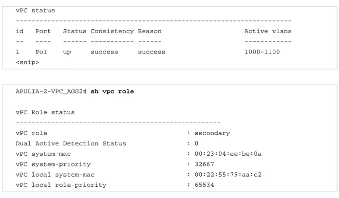
Sample output of these commands are shown below: APULIA-2-VPC_AGG2# sh vpc
Legend:
(*) - local vPC is down, forwarding via vPC peer-link
vPC domain id : 10
Peer status : peer adjacency formed ok vPC keep-alive status : peer is alive Configuration consistency status : success
Type-2 consistency status : success Type-2 consistency reason : success
vPC role : secondary Number of vPCs configured : 6
Track object : 1 Peer Gateway : Enabled Dual-active excluded VLANs : -
vPC Peer-link status
--- id Port Status Active vlans
-- ---- --- --- 1 Po10 up 1-20,23-24,40,50,100,200,300,400-401,501,600,1000-1100
© 2015-2016 Cisco and/or its affiliates. All rights reserved. This document is Cisco Public Information. Page 17 of 129 vPC status
--- id Port Status Consistency Reason Active vlans -- ---- --- --- --- --- 1 Po1 up success success 1000-1100 <snip>
APULIA-2-VPC_AGG2# sh vpc role
vPC Role status
---
vPC role : secondary
Dual Active Detection Status : 0
vPC system-mac : 00:23:04:ee:be:0a
vPC system-priority : 32667
vPC local system-mac : 00:22:55:79:aa:c2
vPC local role-priority : 65534
check that vPC local system mac is derived from system or VDC mac address: APULIA-2-VPC_AGG2# sh vdc
vdc_id vdc_name state mac lc
--- --- --- --- ---
2 VPC_AGG2 active 00:22:55:79:aa:c2 m1 f1 m1xl
vPC system-mac and vPC local system-mac are both used in the LACP protocol as the LACP system ID. However, vPC system-mac is used only with vPC attached access devices while vPC local system-mac is used with single attached devices (orphan port or active/standby with or without STP)
Figure 10 illustrates how vPC system-mac and vPC local system-mac are used.
In this figure, the Cisco Nexus 5000 Series device 1 (5K_1) is forming a local port-channel with the Cisco Nexus 7000 Series device 1 (7K_1). As a result, 7K_1 will use its vPC local system-mac to exchange LACP information with 5K_1.
On the contrary, the Cisco Nexus 5000 Series device 2 (5K_2) is forming a vPC with the Cisco Nexus 7000 Series device 1 (7K_1) and Cisco Nexus 7000 Series device 2 (7K_2). As a result, both 7K_1 and 7K_2 will use their common vPC system-mac to exchange LACP information with 5K_2.
© 2015-2016 Cisco and/or its affiliates. All rights reserved. This document is Cisco Public Information. Page 18 of 129
Figure 10. Use of vPC System-Mac and vPC Local System-Mac
show lacp neighbor on 5K_1 displaysLACP system ID used by 7K_1 (which is the vPC local system-mac): 5K_1# sh lacp neighbor interface port-channel 1
Flags: S - Device is sending Slow LACPDUs F - Device is sending Fast LACPDUs A - Device is in Active mode P - Device is in Passive mode port-channel1 neighbors
Partner's information
Partner Partner Partner
Port System ID Port Number Age Flags
Eth1/4 32667, 0-22-55-79-ab-42 0x4206 18999 SA
LACP Partner Partner Partner
Port Priority Oper Key Port State
32768 0x8001 0x3d
Partner's information
Partner Partner
Partner
Port System ID Port Number Age Flags Eth1/5 32667,0-22-55-79-ab-42 0x4208 18999 SA
LACP Partner Partner Partner
Port Priority Oper Key Port State
32768 0x8001 0x3d
show lacp neighbor on 5K_2 displaysLACP system ID used by 7K_1 and 7K_2 (which the common vPC system-mac):
© 2015-2016 Cisco and/or its affiliates. All rights reserved. This document is Cisco Public Information. Page 19 of 129 5K_2# sh lacp neighbor interface port-channel 1
Flags: S - Device is sending Slow LACPDUs F - Device is sending Fast LACPDUs A - Device is in Active mode P - Device is in Passive mode port-channel1 neighbors
Partner's information
Partner Partner Partner
Port System ID Port Number Age Flags Eth1/1 32667,0-23-4-ee-be-a 0x4206 18999 SA
LACP Partner Partner Partner
Port Priority Oper Key Port State
32768 0x8001 0x3d
Partner's information
Partner Partner Partner
Port System ID Port Number Age Flags
Eth1/2 32667,0-23-4-ee-be-a 0x4208 18999 SA
LACP Partner Partner Partner Port Priority Oper Key Port State 32768 0x8001 0x3d
vPC Role
There are two defined vPC roles: primary and secondary.
vPC role defines which of the two vPC peer devices processes Bridge Protocol Data Units (BPDUs) and responds to Address Resolution Protocol (ARP).
Use role priority <value> command (under vPC domain configuration context) to force vPC role to primary for a dedicated peer device.
<value> ranges from 1 to 65535 and the lowest value will dictate the primary peer device.
In case of tie (same role priority value defined on both peer devices), lowest system mac will dictate the primary peer device.
To know which of the 2 peer devices is primary or secondary, use show vpc role command: APULIA-1-VPC_AGG1# sh vpc role
vPC Role status
---
vPC role : primary
Dual Active Detection Status : 0
© 2015-2016 Cisco and/or its affiliates. All rights reserved. This document is Cisco Public Information. Page 20 of 129
vPC system-priority : 32667
vPC local system-mac : 00:22:55:79:ab:42
vPC local role-priority : 2
APULIA-2-VPC_AGG2# sh vpc role
vPC Role status
---
vPC role : secondary
Dual Active Detection Status : 0
vPC system-mac : 00:23:04:ee:be:0a
vPC system-priority : 32667
vPC local system-mac : 00:22:55:79:aa:c2
vPC local role-priority : 65534
General Recommendation:
For ease of operations, define vPC primary peer device on the left Nexus 7000 series device. Define vPC secondary peer device on the right Nexus 7000 series device.
vPC role (primary or secondary) matters for the behavior in a peer-link failure. As Figure 11 illustrates, when a peer-link failure occurs, only the secondary peer device shuts its vPC member ports to down state and in addition shuts all its vPC VLAN interface (or SVIs - Switch Virtual Interface) [SVI associated to vPC VLAN].
Figure 11. vPC Peer-Link Failure - Behavior On Secondary Peer Device
vPC also adds the concept of operationa role: operational primary and operational secondary. vPC primary or secondary role is dictated by the CLI configuration with role priority command.
© 2015-2016 Cisco and/or its affiliates. All rights reserved. This document is Cisco Public Information. Page 21 of 129
Once vPC domain is powered up, vPC role is always equal to vPC operational role. However, as the network lives and encounters some operational events, the operational role may afterwards differ from the original vPC role. The following sequence shows an example of divergence between vPC role and vPC operational role:
Figure 12. vPC Role and vPC Operational Role
Event 1: vPC devices powered up 7K_1: vPC role = primary 7K_2: vPC = secondary Event 2: 7K_1 reloads and recovers 7K_1: vPC role = primary, operational
secondary
7K_2: vPC role = secondary, operational primary
Event 3: 7K_2 reloads and recovers 7K_1: vPC role = primary 7K_2: vPC role = secondary
vPC role is nonpreemptive so vPC operational role is the most relevant of the 2 information.
Note: To preempt manually the operational primary role for a vPC peer device, administrator must perform following procedure: Log in to the peer device you want to change to operational primary role and configure role priority with a lower value than the other peer device. Then bounce the vPC peer-link (shut, then no shut) to force the change.
Be careful that this operation is disruptive as operational secondary peer device will shut its vPC member ports once peer-link is down.
CLI alias facility can be used to automate the sequence of commands to change vPC operational role: cli alias name vpcpreempt conf t; vpc domain 1; role priority 1; int po 1; shut; no sh
Cisco Fabric Services (CFS) Protocol
Cisco Fabric Services (CFS) protocol provides reliable synchronization and consistency check mechanisms between the 2 peer devices and runs on top of vPC peer-link. The protocol was first implemented on MDS products (network storge devices) and then ported to NEXUS 7000.
Cisco Fabric Services (CFS) protocol performs the following functions:
● Configuration validation and comparison (consistency check)
● Synchronization of MAC addresses for vPC member ports
© 2015-2016 Cisco and/or its affiliates. All rights reserved. This document is Cisco Public Information. Page 22 of 129 ● Spanning Tree Protocol management
● Synchronization of HSRP and IGMP snooping
Cisco Fabric Services is enabled by default when vPC feature is turned on.
There is no specific Cisco Fabric Services configuration to implement. Figure 13 shows the Cisco Fabric Services message path in a vPC domain.
Cisco Fabric Services messages are encapsulated in standard Ethernet frames that are delivered between peers exclusively on the peer-link. Cisco Fabric Services messages are tagged with CoS = 4 for reliable communication.
Figure 13. CFS Message Path in a vPC Domain
To check the Cisco Fabric Services application for vPC and Cisco Fabric Services status, use show cfs application and show cfs status commands, as follows:
7K1# sh cfs application
--- Application Enabled Scope
--- arp Yes Physical-eth
pim Yes Physical-eth stp Yes Physical-eth vpc Yes Physical-eth igmp Yes Physical-eth l2fm Yes Physical-eth
7K1# sh cfs status
Distribution: Enabled
Distribution over IP: Disabled
IPv4 multicast address: 239.255.70.83 IPv6 multicast address: ff15::efff:4653
© 2015-2016 Cisco and/or its affiliates. All rights reserved. This document is Cisco Public Information. Page 23 of 129 Distribution over Ethernet: Enabled
Checking vPC Configuration Consistency When You Build a vPC Domain
This section contains recommendations to help ensure that there are no incompatible parameters when building a vPC domain.
Both switches in the vPC domain maintain distinct control planes. Cisco Fabric Services protocol will take care of state synchronization between both peers (including the MAC address table, Internet Group Management Protocol (IGMP) state, vPC states and so on.)
System configuration must be kept in sync. Currently this is a manual process (configuration is done separately on each device) with an automated consistency check to help ensure correct network behavior.
There are two types of consistency checks:
● Type 1 - Puts peer device or interface into a suspended state to prevent invalid packet forwarding behavior. With vPC Graceful Consistency check, suspension occurs only on the secondary peer device.
● Type 2 - Peer device or Interface still forward traffic. However they are subject to undesired packet forwarding behavior.
Type 1 and Type 2 consistency check apply both for global configuration and for vPC interface configuration.
Configuration Parameters That Must Be Identical (Type-1 Consistency Check)
After you enable vPC feature and configure vPC peer-link on both peer devices, Cisco Fabric Services messages provide a copy of the configuration on the local vPC peer device to the remote vPC peer device. The system then determines whether any of the crucial configuration parameters differ on the two devices.
Many global configuration parameters must be identical as well as vPC interfaces parameters in the same vPC domain.
The devices automatically check for compatibility. The per-interface parameters must be consistent per interface, and the global parameters must be consistent globally.
When Type 1 inconsistency check is detected, radical actions are taken:
For global configuration type 1 inconsistency check, all vPC member ports are set to down state. For vPC interface configuration type 1 inconsistency check, the misconfigured vPC is set to down state. Since NX-OS version 5.2, graceful consistency check has been introduced to soften vPC system reaction in occurrence to type 1 consistency check:
For global configuration type 1 inconsistency check, only vPC member ports on secondary peer device are set to down state.
For vPC interface configuration type 1 inconsistency check, only vPC member ports on secondary peer device are set to down state.
Enter the show vpc consistency-parameters command to display the global configuration values and vPC interfaces parameters. The displayed output are only those configurations that would limit the vPC from coming up.
© 2015-2016 Cisco and/or its affiliates. All rights reserved. This document is Cisco Public Information. Page 24 of 129
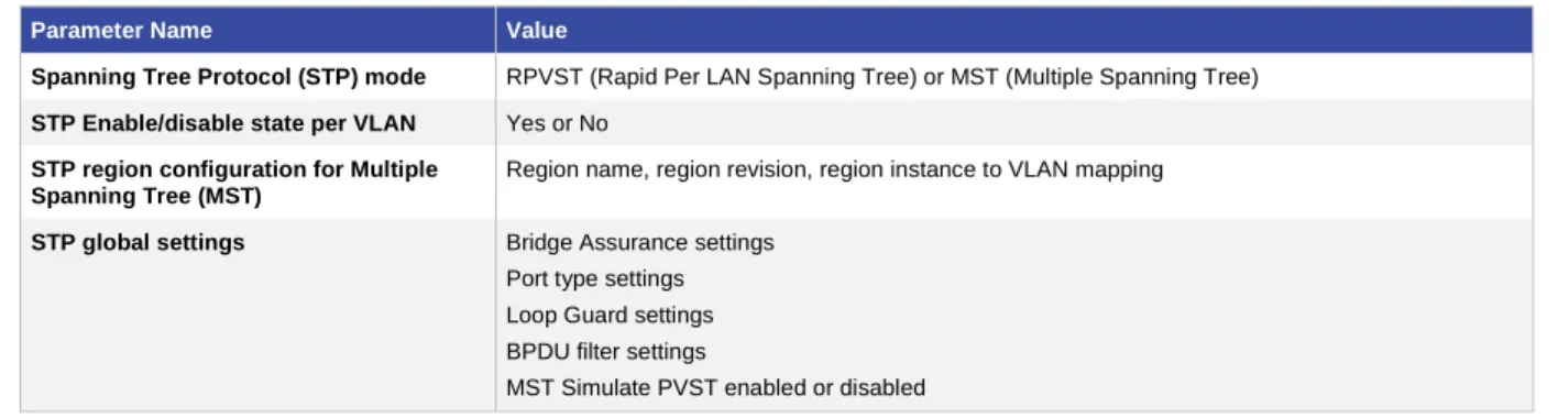
Table 2 lists global configuration parameters that are taken into account for type-1 consistency check.
Table 2. Global configuration Type-1 Consistency Check
Parameter Name Value
Spanning Tree Protocol (STP) mode RPVST (Rapid Per LAN Spanning Tree) or MST (Multiple Spanning Tree)
STP Enable/disable state per VLAN Yes or No
STP region configuration for Multiple Spanning Tree (MST)
Region name, region revision, region instance to VLAN mapping
STP global settings Bridge Assurance settings Port type settings Loop Guard settings BPDU filter settings
MST Simulate PVST enabled or disabled
show vpc consistency-parameters global command displays global type 1 consistency parameters. An example of output is shown below:
7K1# sh vpc consistency-parameters global
Legend:
Type 1: vPC will be suspended in case of mismatch
Name Type Local Value Peer Value
--- ---- --- ---
STP Mode 1 Rapid-PVST Rapid-PVST
STP Disabled 1 None None STP MST Region Name 1 "" "" STP MST Region Revision 1 0 0 STP MST Region Instance to 1
VLAN Mapping
STP Loopguard 1 Disabled Disabled STP Bridge Assurance 1 Enabled Enabled STP Port Type, Edge 1 Normal, Disabled, Normal, Disabled, BPDUFilter, Edge BPDUGuard Disabled Disabled STP MST Simulate PVST 1 Enabled Enabled Interface-vlan admin up 2 200,3966-3967 200,3966-3967 Interface-vlan routing 2 1,40,200,3966-3967 1,40,200,3966-3967 capability
Allowed VLANs - 1-20,23-24,40,50,100,2 1-20,23- 24,40,50,100,2
00,300,501,600,1000-11
00,300,501,600,1000-11
© 2015-2016 Cisco and/or its affiliates. All rights reserved. This document is Cisco Public Information. Page 25 of 129 Local suspended VLANs - - -
Table 3 lists the per vPC interface parameters that are taken into account for type-1 consistency check.
Table 3. Per vPC Interface Type-1 Consistency Check
Parameter Value
Port-channel LACP mode ON, ACTIVE, PASSIVE
Link speed per port-channel Speed in mbps
Duplex mode per port-channel Half duplex or full duplex
Switchport mode per port-channel Trunk or access Native VLAN
STP interface settings Port type setting Loop Guard Root Guard
MST Simulate PVST Enable or disable
MTU per port-channel Maximum transmission Unit (MTU) value
show vpc consistency-parameters interface port-channel <id> command displays per vPC interface type 1 consistency parameters.
An example of output is shown below:
7K1# sh vpc consistency-parameters interface port-channel 80
Legend:
Type 1 : vPC will be suspended in case of mismatch
Name Type Local Value Peer Value --- ---- --- --- STP Port Type 1 Default Default STP Port Guard 1 None None STP MST Simulate PVST 1 Default Default
lag-id 1 [(7f9b, [(7f9b,
0-23-4-ee-be-a,8050, 0-23-4-ee-be-a, 8050,
0, 0), (8000, 0, 0), (8000,
0-22-90-c2-8-3e, 1, 0, 0-22-90-c2-8-3e, 1, 0,
0)] 0)]
mode 1 active active Speed 1 1000 Mb/s 1000 Mb/s Duplex 1 full full Port Mode 1 trunk trunk Native Vlan 1 1 1
MTU 1 1500 1500
Allowed VLANs - 100,200,300 100,200,300
© 2015-2016 Cisco and/or its affiliates. All rights reserved. This document is Cisco Public Information. Page 26 of 129
Configuration Parameters That Should Be Identical (Type-2 Consistency Check)
When Type 2 inconsistency check is detected, moderate action or no action are taken:
For global configuration type 2 inconsistency check, all vPC member ports remain in up state and vPC systems trigger to protective actions.
For vPC interface configuration type 2 inconsistency check, the misconfigured vPC remains in up state. However, depending on the discrepancy type, vPC systems will trigger protective actions. The most typical one deals with allowed VLAN in vPC interface trunking configuration. In that case, vPC systems will disable from the vPC interface VLAN that do not match on both sides.
Table 4 lists type 2 consistency check parameters.
Some global configuration consistency check parameters appear in sh vpc consistency-parameters global (mentioned above). However, most of vPC interface parameters (for type 2 consistency check) do not appear in sh vpc consistency-parameters interface port-channel command.
If any of the parameters listed in Table 3 is not configured identically on both vPC peer devices, the inconsistent configuration can cause undesirable behavior in the traffic flow.
Table 4. Type-2 Consistency Parameters
Parameter Description
MAC aging timers MAC aging timer for a particular VLAN should be the same on both vPC peer devices.
Static MAC entries Static MAC entries in a particular VLAN should be applied on both vPC peer devices.
VLAN interface (switch virtual interface [SVI])
Each peer device must have a VLAN interface configured for the same VLAN on both ends, and this VLAN interface must be in the same operational state.
Access Control List (ACL) configurations and parameters
ACL configurations should be identical on both vPC peer devices.
Quality of Service (QoS) configuration and parameters
QoS configuration should be identical on both vPC peer devices.
Spanning Tree Protocol interface settings
Bridge Protocol Data Unit (BPDU) filter Link type (auto, point-to-point, shared) Cost
Port-priority
STP interface settings should be identical on both vPC peer devices.
VLAN database You must create all VLANs on both the primary and secondary vPC peer devices, or the VLAN will be suspended. Those VLANs configured on only one peer device do not pass traffic using the vPC or vPC peer-link.
Port security Network Access Control (NAC) Dynamic ARP Inspection (DAI) IP source guard (IPSG)
Port security settings should be identical on both vPC peer devices.
Cisco TrustSec Cisco TrustSec configuration should be identical on both vPC peer devices.
Dynamic Host Configuration Protocol (DHCP) snooping
DHCP snooping configuration should be identical on both vPC peer devices.
Internet Group Management Protocol (IGMP) snooping
IGMP snooping configuration should be identical on both vPC peer devices.
Hot Standby Router Protocol (HSRP)
© 2015-2016 Cisco and/or its affiliates. All rights reserved. This document is Cisco Public Information. Page 27 of 129
Parameter Description
Protocol Independent Multicast (PIM)
PIM configuration should be identical on both vPC peer devices.
Gateway Load-Balancing Protocol (GLBP)
GLBP configuration should be identical on both vPC peer devices.
All routing protocol configurations Routing configuration should be consistent on both vPC peer devices.
General Recommendation:
To help ensure that all the configuration parameters are compatible, we recommend that you display the configurations for each vPC peer device once you configure the vPC.
Building a vPC Domain: Guidelines and Restrictions
To build a vPC domain, use the following configuration guidelines:
● You must enable feature vPC (conf t; feature vpc) before you can start configuring a vPC domain.
● You must configure peer-keepalive link before peer-link in order for vPC system to come up.
● You must configure both vPC peer devices; the configuration is not sent from one device to the other.
● To configure double-sided vPC topology, you must assign a unique vPC domain ID for each respective vPC layer.
● To use vPC in a DCI topology, you must assign a unique vPC domain ID for each respective data center.
● Check that the necessary configuration parameters are consistent on both sides of the vPC peer-link.
● We recommend that you activate the LACP feature and configure vPC member ports with LACP mode set to ACTIVE.
● All ports for a given vPC peer must be in the same VDC.
● Only Layer 2 port channels (switchport mode trunk or switchport mode access) can be configured on vPC member ports.
● PIM SM (Sparse Mode) is fully interoperable with vPC. The software does not support PIM BiDIR or PIM SSM (Source Specific Multicast) with vPC.
● The software does not support DAI (Dynamic ARP Inspection) or IPSG (IP Source Guard) in a vPC environment.
● DHCP relay and DHCP snooping are supported with vPC.
● The software does not support Cisco Fabric Services regions with vPC.
● Port security is not supported on vPC member ports.
● Configure a separate Layer 3 link for routing from the vPC peer device (backup routing path), rather than using vPC peer-link and SVI for this purpose.
● We recommend that you create an additional Layer 2 trunk port-channel as an interswitch link to transport non-vPC VLAN traffic.
Note: When using vPC, it is a best practice to use default timers for HSRP (Hot Standby Router Protocol), VRRP (Virtual Router Redundancy Protocol) and PIM (Protocol Independent Multicast) configurations.
© 2015-2016 Cisco and/or its affiliates. All rights reserved. This document is Cisco Public Information. Page 28 of 129
Best Practices for vPC Components Configuration
The following sections provide recommendations to configure the different vPC components: vPC VLAN, vPC Peer-keepalive link, vPC peer-link, vPC member ports.
Specific consideration for vPC peer-link using only 1 10G module in the chassis is also discussed in this chapter.
Recommendation for vPC VLAN Configuration
vPC VLAN is a VLAN that is allowed on vPC member port and vPC peer-link.
The first step to make a switch working is to create the VLAN database. Enter the following command in global configuration mode:
N7k(config) # vlan <vlan-id range>
When configuring large number of VLAN in vPC environment, it is recommended to configure the VLANs using range command, instead of individually configuring one VLAN at a time.
If you need to name the different VLAN, create first all the VLAN using range command. Exit from global configuration mode to make effective VLAN creation. Then name each VLAN as needed.
Strong Recommendation:
When configuring large number of VLAN in vPC environment, it is recommended to configure the VLANs using range command, instead of individually configuring one VLAN at a time.
Recommendations for vPC Peer-Keepalive Link Configuration
vPC peer-keepalive link is a Layer 3 link that joins one vPC peer device to the other vPC peer device, as illustrated in Figure 14.
Figure 14. vPC Peer-Keepalive Link
The vPC peer-keepalive link carries periodic heartbeat between vPC peer devices. It is used at the boot up of the vPC systems to guarantee both peer devices are up before forming vPC domain and also when vPC peer-link fails to down state; in the latter case, vPC peer-keepalive link is leveraged to detect split brain scenario (both vPC peer devices are active-active) [when vPC peer-link is down, there is no more real time synchronization between the 2
© 2015-2016 Cisco and/or its affiliates. All rights reserved. This document is Cisco Public Information. Page 29 of 129
peer devices so vPC systems must react to this active-active situation; this is done by shutting down vPC member ports on secondary peer device].
In term of data structure, a vPC peer-keepalive message is a User Datagram Protocol (UDP) message on port 3200 that is 96 bytes long, with a 32-byte payload. Keepalive messages can be captured and displayed using the onboard Wireshark Toolkit.
Table 5 lists default values for vPC peer-keepalive link timers and Figure 15 illustrates the vPC timers concept.
Table 5. Default Values for vPC Peer-Keepalive Links
Timer Default value
Keepalive interval 1 seconds
Keepalive hold timeout (on vPC peer-link loss) 3 seconds
Keepalive timeout 5 seconds
Figure 15. vPC Timers Concept
Keepalive Hold Timeout
This timer gets started once the vPC peer-link goes to down state. During this time period, the secondary vPC peer device will ignore any peer-keepalive hello messages (or the lack of). This is to assure that network convergence can happen before any action is taken.
Keepalive Timeout
During this time period, the secondary vPC peer device will look for vPC peer-keepalive hello messages from the primary vPC peer device. If a single hello is received, the secondary vPC peer concludes that there must be a dual active scenario and therefore will disable all its vPC member ports (that is, all port-channels that carry the keyword vpc).
Command line configuration to modify vPC timers is (under vPC domain configuration context):
N7k(config-vpc-domain)# peer-keepalive destination ipaddress [source ipaddress | hold-timeout secs | interval msecs {timeout secs}]
The show vpc peer-keepalive command displays all information about peer-keepalive link, as follows: 7K1# sh vpc peer-keepalive
© 2015-2016 Cisco and/or its affiliates. All rights reserved. This document is Cisco Public Information. Page 30 of 129 vPC keep-alive status : peer is alive
--Peer is alive for : (22) seconds, (255) msec --Send status : Success
--Last send at : 2011.06.07 15:24:28 339 ms --Sent on interface : Eth1/24
--Receive status : Success
--Last receive at : 2011.06.07 15:24:27 597 ms --Received on interface : Eth1/24
--Last update from peer : (0) seconds, (857) msec
vPC Keep-alive parameters
--Destination : 192.168.100.2 --Keepalive interval : 1000 msec --Keepalive timeout : 5 seconds --Keepalive hold timeout : 3 seconds --Keepalive vrf : peerkeepalive --Keepalive udp port : 3200
--Keepalive tos : 192
Strong Recommendations:
When building a vPC peer-keepalive link, use the following in descending order of preference:
1. Dedicated link(s) (1-Gigabit Ethernet port is enough) configured as L3. Port-channel with 2 X 1G port is even better.
2. Mgmt0 interface (along with management traffic)
3. As a last resort, route the peer-keepalive link over the Layer 3 infrastructure
WARNING: Do not configure vPC peer-keepalive link on top of vPC peer-link; peer-keepalive messages must not be carried over vPC peer-link to avoid fate sharing in case peer-link goes down.
Note: If you are using a pure Cisco Nexus F1 Series system or VDC (that is, only F1 line cards used in the chassis or only F1 ports in the VDC), the peer-keepalive link can be formed with mgmt0 interface or 10-Gigabit Ethernet front panel port. In the latter case, use the management command under the SVI to enable it for inband management (otherwise, the SVI is brought down because no M1 modules exist in the system or VDC).
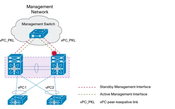
vPC Peer-Keepalive Link Using mgmt0 Cisco Nexus 7000 Series Pairs with Dual Supervisors Each When using dual supervisors and mgmt0 interfaces to carry the vPC peer-keepalive link, do not connect mgmt0 ports in back-to-back mode across the two switches (i.e mgmt0 on supervisor 1 of peer device 1 connected directly to mgmt0 on supervisor 1 of peer device 2 and so on). Reason is that active supervisor owns control of mgmt0 port and in case of supervisor switchover, keep-alive connectivity may be broken (active supervisor on peer device 1 sending keep-alive to standby supervisor on peer device 2).
© 2015-2016 Cisco and/or its affiliates. All rights reserved. This document is Cisco Public Information. Page 31 of 129
Best practice is to insert a L2 switch between the different supervisors to avoid this kind of situation as depicted in figure 16.
Figure 16. vPC Peer-Keepalive Link Using mgmt0 and Dual Supervisors
Strong Recommendation:
When using mgmt0 port for vPC peer-keepalive link in a dual supervisor configuration, always use an intermediate L2 switch to interconnect the different supervisors together.
vPC Peer-Keepalive Link and VRF
By default, vPC peer-keepalive is placed in VRF management.
If needed, vPC peer-keepalive can be placed in another VRF using the following command (under vPC domain configuration context):
N7k(config-vpc-domain)# peer-keepalive destination <destination IP> source <source IP> vrf <VRF name> General Recommendation:
Create a dedicated VRF for vPC peer-keepalive link (for instance VRF PKL-VRF)
Recommendations for vPC Peer-Link Configuration
The vPC peer-link is a standard 802.1Q trunk that can perform the following actions:
● Carry vPC and non-vPC VLANs.
● Carry Cisco Fabric Services messages that are tagged with CoS=4 for reliable communication.
● Carry flooded traffic from the other vPC peer device.
© 2015-2016 Cisco and/or its affiliates. All rights reserved. This document is Cisco Public Information. Page 32 of 129
It is at the vPC peer-link level that we implement vPC loop avoidance mechanism (data plane layer). This is done in hardware, without any software sollicitation.
Figure 17 shows vPC peer-link component in a vPC domain.
Figure 17. vPC Peer-Link
Strong Recommendations:
When building a vPC peer-link, follow these guidelines:
● Ensure that member ports are 10-Gigabit Ethernet interfaces.
● Use a minimum of two 10-Gigabit Ethernet ports. vPC peer-link member ports can be scaled up to line card capacity in regards to port-channel (M1 line card supports up to 8 members ports while F1 and F2 support up to 16 member ports).
● Use at least 2 different line cards to increase high availability of peer-link.
● Use dedicated 10-Gigabit Ethernet ports with M1 32 10G line card. Do not use shared mode ports.
● Split vPC and non-vPC VLANs on different interswitch port channels (use vPC peer-link to carry vPC VLAN and the other interswitch port-channel to carry non-vPC VLAN).
● Do not insert any device between vPC peers. A peer-link is a point-to-point link.
vPC peer-link is supported on all shipping 10G line card. It is not supported on any 1G line card nor on any FEX ports (including the 2232 model which has 10G front panel ports).
Table 6 list all line cards that are able to support vPC peer-link
Table 6. Supported line cards for vPC peer-links.
Line Card Part Number Line Card Description
N7K-M132XP-12 N7K-M132XP-12L
32 10-Gigabit Ethernet port M1- Series
N7K-M108X2-12L 8 10-Gigabit Ethernet port M1- Series
N7K-F132XP-15 32 1/10-Gigabit Ethernet port F1 Series
© 2015-2016 Cisco and/or its affiliates. All rights reserved. This document is Cisco Public Information. Page 33 of 129
vPC Peer-link can be formed with M1 ports on both sides (M1 to M1), or F1 ports on both sides (F1 to F1), or F2 ports on both sides (F2 to F2). It is mandatory that both sides of vPC peer-link are strictly identical.
As a consequence, it is not possible to mix F1 port on 1 side and M1 port on the other side (for instance). The M132XP and M108X2 (that is, a 32 10-Gigabit Ethernet line card and 8 10-Gigabit Ethernet line card, respectively) can form a port-channel together. However, be aware of the requirement that ports on M132XP can form a port-channel with ports on M108X2 only if the port is configured in dedicated mode.
This is consistent with vPC peer-link recommendations: vPC peer-link member ports should have full 10-Gigabit Ethernet capability - in other words, no oversubscription.
Supported and unsupported configurations are depicted in figure 18 and 19.
© 2015-2016 Cisco and/or its affiliates. All rights reserved. This document is Cisco Public Information. Page 34 of 129
Figure 19. Unsupported Configurations for vPC Peer-Links (Both Sides Must Be of Same Port Type)
It is not possible to mix different port type inside the same vPC peer-link side (for example bundling M1 port and F1 port on same side of the vPC peer-link) because each port type have different hardware characteristics (in terms of forwarding, queuing, and security).
This rule does not only apply to vPC peer-link; this is a generic statement for port-channel.
Note: In case of mixed chassis mode (that is, with an M1 and F1 ports in the same system or same VDC) and vPC peer-link on F1 ports, be careful if you use the vPC peer-gateway feature and backup routing path capability. Starting with Cisco NX-OS Release 5.1.3, a knob is available to exclude specific VLANs from the peer-gateway. These VLANs are typically used for backup routing paths. The command is:
N7k(config-vpc-domain)# peer-gateway exclude-vlan <VLAN list>
The knob is not useful in the other configurations of vPC systems and vPC peer-link. More details are provided in the peer-gateway section of this document.
For unicast traffic, vPC peer devices always use local forwarding preference using vPC member port. vPC peer-links is usually not loaded with unicast traffic unless vPC member port fail on 1 side of vPC domain. For multicast traffic, a copy of the stream is replicated on vPC peer-link (except when vPC peer-link is built with F2 ports as the line card do not support dual DR [Designated Router] in multicast environment).
This type of traffic needs to be taken into account when dimensioning the vPC peer-link. To view statistics for vPC peer-link, use the command show vpc statistics peer-link.
© 2015-2016 Cisco and/or its affiliates. All rights reserved. This document is Cisco Public Information. Page 35 of 129
One important aspect related to vPC peer-link is VLAN pruning. For a vPC VLAN to become operational, it must be defined on vPC peer-link using the command:
N7k(config)# interface port-channel 1 (int Po1: vPC peer-link)
N7k(configif)# switchport trunk allowed vlan <VLAN-id list>
Of course, vPC VLAN has previously been allowed (i.e pruned) on vPC member port. Required Recommendation:
Always perform VLAN pruning on vPC peer-link with allowed list of vPC VLAN. vPC VLAN must have been pruned on vPC member port previously.
vPC Systems Behavior When a vPC Peer-Link Goes Down
When vPC peer-link fails down and vPC peer-keepalive link is still up, the vPC secondary peer device performs the following operations:
● Suspends its vPC member ports
● Shuts down the SVI associated to the vPC VLAN
This protective behavior from vPC allows to redirect all southbound and northbound traffic to primary peer device. Note that when vPC peer-link is down, both vPC peer devices cannot synchronize each other anymore so designed protection mechanism leads to isolate one of the peer device (in occurrence the secondary peer device) from the data path.
Figure 20 illustrates what happens when a vPC peer-link fails down
Figure 20. vPC Peer-Link Down - Behavior on Secondary Peer Device
If orphan ports are connected to vPC secondary peer device, they become isolated once peer-link is down. In a VXLAN + vPC implementation, when a vPC peer-link shuts down, all Layer 2 or Layer 3 orphan receivers behind the non-forwarder (shut down vPC peer-link) will not receive any traffic.
To maintain Layer 3 connectivity to these orphan ports, a command is available to prevent the SVI (associated to vPC VLAN) from being shut down: dual-active exclude interface-vlan.
© 2015-2016 Cisco and/or its affiliates. All rights reserved. This document is Cisco Public Information. Page 36 of 129
Use this command to keep desired SVI in UP state when vPC peer-link goes down:
N7k(config-vpc-domain)# dual-active exclude interface-vlan <VLAN list>
VLAN listed in the knob must be associated to vPC VLAN. Using a non-vPC VLAN has no effect since SVI associated to these VLAN are not shut down when vPC peer-link goes down.
Recommendations for vPC Peer-Link Configuration with Systems Containing Only One M1 10-Gbps Module
Some Cisco Nexus 7000 Series Switch configurations have only one M1 10-Gbps module and several 1-Gbps modules. Problems may occur if these Switches are defined as Layer 2/Layer 3 boundary (that is, same 10-Gbps line card used for both Layer 3 uplinks connectivity and for vPC peer-link).
For this type of configuration, it is necessary to use vPC Object Tracking feature (available since NX-OS 4.2) vPC Object Tracking
vPC object tracking is used to track failure of all modules on a Cisco Nexus 7000/7700 Series switch on wich peer-link and uppeer-links are hosted. It is also used when the L3 core peer-links and vPC peer-peer-link interfaces are localised on the same module and it fails.
Without the vPC object tracking feature enabled, if the module/modules fails on the vPC primary device that hosts the peer-link and ulinks, it will lead to a complete traffic blackhole even though the vPC secondary device is up and running.
This happens because the module hosting the peer-link fails and the peer-link goes down and vPC secondary device suspends all vPC (vPC loop prevention). The vPC’s on the vPC primary will be still up but as the
module/modules hosting the uplinks have failed, therefore the uplinks will be down and traffic (south to north) will be dropped.
Figure 21 illustrates the effect of the vPC Object Tracking feature.
© 2015-2016 Cisco and/or its affiliates. All rights reserved. This document is Cisco Public Information. Page 37 of 129
The vPC Object Tracking feature suspends the vPCs on the impaired device so that traffic can be diverted over the remaining vPC peer.
To use vPC object tracking, track both Peer-link interfaces and L3 core interfaces as a list of Boolean objects. Note that the Boolean AND operation is not supported with vPC object tracking.
The vPC object tracking configuration must be applied on both vPC peer devices.
Following configuration sample shows the different commands needed to activate vPC object tracking: ! Track the vpc peer link
track 1 interface port-channel11 line-protocol
! Track the uplinks to the core
track 2 interface Ethernet1/1 line-protocol track 3 interface Ethernet1/2 line-protocol
! Combine all tracked objects into one.
! “OR” means if ALL objects are down, this object will go down ! ==> we have lost all connectivity to the L3 core and the peer link
track 10 list boolean OR object 1
object 2 object 3
! If object 10 goes down on the primary vPC peer,
! system will switch over to other vPC peer and disable all local vPCs
vpc domain 1 track 10
Strong Recommendation:
© 2015-2016 Cisco and/or its affiliates. All rights reserved. This document is Cisco Public Information. Page 38 of 129
Recommendations for vPC Member Port Configuration
By definition, a vPC member port is a port-channel member of a vPC, as illustrated in Figure 22.
Figure 22. vPC Member Port
Port-channel defined as vPC member port always contains the keywords vpc <vpc id>.
Port-channel member port contain from 1 member port up to the hardware limit of the line card (M1 series line card support up to 8 member ports while F1 and F2 series line card support up to 16 member ports).
A Layer 2 port-channel only is supported with vPC (no Layer 3). The port-channel can be configured in access or trunk switchport mode. Any VLAN allowed in the vPC member port is by definition called vPC VLAN. The vPC VLAN must then be allowed on vPC peer-link.
Note: Whenever a vPC VLAN is defined on vPC member port, it MUST be defined also on vPC peer-link. Not defining a vPC VLAN on vPC peer-link will will make the VLAN not operational. Required Recommendation:
Any vPC VLAN allowed on vPC member port MUST be allowed on vPC peer-link. Below is a sample configuration of vPC member port:
7K1:
interface port-channel201 switchport mode trunk
switchport trunk native vlan 100 switchport trunk allowed vlan 100-105 vpc 201
7K2:
interface port-channel201 switchport mode trunk
switchport trunk native vlan 100 switchport trunk allowed vlan 100-105 vpc 201
© 2015-2016 Cisco and/or its affiliates. All rights reserved. This document is Cisco Public Information. Page 39 of 129
Use the following recommendations to build properly vPC member port: Strong Recommendations:
● The configuration of vPC member port must match on both vPC peer devices.
● If there is an inconsistency, a VLAN or the entire port channel may suspend (depending on type-1 or type-2 consistency check for the vPC member port). For instance, a MTU mismatch will suspend the vPC member port.
● Use same vPC ID as port-channel ID for ease of configuration, monitoring, and troubleshooting.
● With the M1 Series line card: There can be up to eight active ports bundled in the same vPC member port (allowing as a result a 16-way port channel to be built for the whole vPC).
● With F1 and F2 Series line card: There can be up to 16 active ports bundled in the same vPC member port (allowing as a result a 32-way port channel to be built for the whole vPC).
● Do not mix different port types (M1 port, F1 port or F2 port) in the same vPC member port. This is not allowed by the software.
● Both sides of the vPC member ports (i.e vPC member port on 7K1 and vPC member port on 7K2) must be of same port type (M1 port or F1 port or F2 port).
A vPC can be formed with same port type on both sides (i.e on both vPC peer devices):
If vPC member port uses M1 ports type on peer device 1, then vPC member port on peer device 2 must use M1 ports type as well. Same statement applies for F1 and F2 ports type.
It is not possible to mix different port types on same vPC member port (also true for port-channel) because these ports have different hardware characteristics (in terms of forwarding, queuing, and security).
© 2015-2016 Cisco and/or its affiliates. All rights reserved. This document is Cisco Public Information. Page 40 of 129
Supported and unsupported vPC member port configurations are depicted in Figures 23 and 24:
Figure 23. Supported Configurations for vPC Member Ports
Figure 24. Unsupported Configurations for vPC Member Ports
Note: M132XP and M108X2 (32 10-Gigabit Ethernet line cards and 8 10-Gigabit Ethernet line cards,
respectively) can form a port-channel together and then can co-exist in the same vPC member port. However, be aware of the requirement that ports on M132XP can form a port-channel or vPC member port with ports on M108X2 only if M132XP ports are configured in dedicated mode.