IP Camera
(HD Cloud IP Camera)
User Manual for WEB Client
Note: To protect your privacy, please change the initial password after login in. Please keep your user name and password safely.
Manual Version:
Version Time Description
V1.0 May 30th,2013 /
V1.1 Sept. 5th,2013 Added scheduled recording function and APP push
notification
V1.2 Dec. 27th,2013 Increased account registration and single device
management password
V1.3 Mar. 29th,2014 Added add device wizard, WPS function, Auto mode
Contents
1.Introduction... 1
2.Installation...1
2.1. Camera installation and login... 1
2.2. Wireless Installation guide... 3
3.Home page... 4
3.1. Camera guide... 4
3.2 Camera status...6
3.3 Account settings... 7
3.4 Image setting & PTZ control... 8
3.5 Mode selection...9
3.6 Interface button...9
3.7 Playback...9
4.Information... 11
4.1 Alarm information review...11
5. Settings... 12
5.1 About... 12
5.2 Nickname...12
5.3 Admin password... 13
5.4 Guest password...14
5.5 Network... 14
5.6 OSD... 17
5.7 Micro SD card... 18
5.8 Camera alarm settings... 19
5.9 Scedule recording... 20
5.10 Date/Time... 21
7. Wireless basis... 26
1. Introduction
Thanks for buying our products. Cloud IP camera has a variety of functions, which dedicates to the office and home solutions. Unlike traditional IP Camera, cloud camera uses P2P technology, plug and play (no need to do port forwarding, DNS, or IP address setting). By using WIFI/3G remote monitoring,Cloud
Camera realizes real-time control at any place and any time. 720P HD makes image clear and smooth. Cloud IP camera also has motion detection function, making it cost-effective for home and public security.
This manual is only for reference, any update please open www.myannke.com to download newest manual version.
2. Installation
2.1. Camera installation and login
Step one: Connect power and network
Please refer to "Quick Installation Guide” for installation Step two: Login
1: Open www.myannke.com on browser, and put in camera ID and password (each IP CAM have a unique ID number and password).
Note: The user can click on the login screen of the "Register" button to register a user account, login to add / manage multiple cameras.
2: On the video viewing screen.
Language Registeratio
n
Enter the ID number or registered account
Password
Login
ID login page
3: Install the plug-in:
Note: If the image blurs when you watch, probably run the focal during
transportations or human factors of the camera lens, the focal length of the lens caused by out of focus, the user can put the camera on the 3 meters for
Registered account login page
Play
Install video plug Account settings
Real-time viedo
Live view shoot
reference, swing the camera lens back and forth a few times till the image in best performance.
2.2. Wireless Installation Considerations
Wireless Camera promises you in the wireless network coverage area to use wireless connection to access the network. However, the wireless signals need to pass through walls, ceilings and other objects, thickness and location of limits Wi-Fi range. The network ranges depending on your room or office types of materials and radio frequency noise. Please follow these basic guidelines to maximize wireless range:
1. Make sure the walls, ceilings between routers and your IP Cameras have as fewer as you can, each wall or ceiling can weaken adapter 3-90 feet (1-30 meters) of the wireless transmission range.
2. Please pay attention to the straight-line distance between the devices. 1.5 feet thick (0.5 meters) of the wall at a 45degree appears to be almost 3 feet (1 meter) thick. When turning to the 2degree, the thickness of the wall will reach 42 feet (14 meters). Put the machine straight through a wall or ceiling (instead of at an angle) for better reception.
3. Building Materials make a difference. Metal door or aluminum studs may weaken the wireless signal. The access points, wireless routers and other networking devices where the signal passes through drywall or not open
doorways. Materials and objects such as glass, steel, metal, band insulator, water (fish tanks), mirrors, file cabinets, brick, and concrete will degrade your wireless signal.
4. Keep your product away from the electronic devices that generate RF noise and appliances at least 3-6 feet or 1-2 meters from the outside position.
5. If you are using 2.4GHz cordless phones or other radio transmitting source devices (such as microwave ovens), your wireless connection may degrade dramatically or drop completely. Make sure your 2.4GHz phone base is as far away from wireless devices. Even if the phone is not in use, the base will still transmit signals.
3. Homepage
3.1 Add Camera Wizard1. Add online cameras
3. Enter Cloud IP Cam password and click add device.
4. Enter Cloud IP Cam password and click revise button.
Attention: 1. the 4th step is based on the Cam’s initial password, if the initial password is not “admin”, this step can be cancelled.
2. The 5th step, after choosing Wi-Fi and enter password, when applying, please check the STATE1 ( ) light flashing status. Before pulling the cable please make sure the STATE1 ( ) flash 3 times for every 3 seconds.
5. After choosing Wi-Fi, enter the password and click apply.
6. Add IP Cam Successfully.
3.2
Camera status
1. You can see the online status of every camera you added, which can be divided into 3 statuses.
•Green color indicates that your camera is online.
• Yellow color means the camera online; however, password has been changed. You need to enter the new password to access the camera. •Red indicates the camera is offline and not able to
access remotely.
If the camera is offline, please try the following methods: • Make sure the camera's network connection is normal. • Try to restart your network router.
• Please check the camera's cable connections to ensure they are connected. • Make sure the camera STATE2 ( )the green light flashes every 3 times
every 3 seconds.
If you still can not access your camera, please restart the camera or press the RESET shortly backing to the factory settings.
2. : Add or delete online cameras.
3.3
Account settings
1. Set video size:User can choose the resolution of the images.
2. Password:User can modify the admin account (The visitors login the account
by administrator password can modify the information of the account). 3. Guest Password: The visitors who login the account by guest password can
only watch and rotating screen, which can't modify the information of the account.
4. Exit: Exit Video Interface.
1. Brightness / Contrast / Saturation / Sharpness: video images can adjust the parameters of the corresponding
(Such as the right to adjust these parameters will result in poor image quality display we may not recommend users adjust of these parameters).
2. : Click "Reset", you can restore brightness / contrast / saturation / sharpness
back to the factory settings.
3. : IP CAM can control PTZ up / down / left / right rotation. 4. : Display and hide the status bar icons.
5. Machine Turnover: When the machine is hosting, the picture is turnover, when choosing Machine Turnover, the picture will turn back.
6. Supply frequency: Please choose the right Supply frequency based on the local area. (China rated frequency is 50Hz).
3.5 Mode selections
1. Automatically: Infrared lamp’s on and off is based on the environment around the photosensitive sensor.
2. Daytime: IP camera is switch into daytime mode, infrared lamp is off. 3. Night: IP camera is switch into night mode, infrared lamp is on.
3.6 Button page
1. Video Play / Stop: Click buttons to play or stop the video.
2. Temporary manual recording button (the file recorded to micro SD card): Click the buttons on the audio / video recording, recording icon indicates .NOTE: This video button function applies only to temporary manually recording.
4. Voice intercom: Click buttons, camera and computer microphone / speakers are turned on; the two sides’ voices can be heard.
3.7. Playback
Micro SD card stores the video files.
1. Select the camera in the camera list.
2. In the image on the right can find more information. Video files and file details.
2. Video files and catalog
1. Camera list
4. Information
4.1
Alarm Information Checking
1. Information checking
2. Open the image
5
.
Management
This section shows the configuration of the IP Cam.
5.1 About
Basic information about the camera is displayed.
Model: The camera version number.
Software Version: Camera current software version number.
Plug-in version: watch current video cameras plug-in version number. Device ID: camera ID.
5.2 Nickname
Nickname: User can modify the name of the camera.
5.3 Admin Password
Admin Password: Enter the current login password (default password is admin). New Password: Enter the new admin password.
(To protect your privacy, please change the initial password after logging. Please keep the user name and password.)
New Password confirmation: Re-enter the current camera modified login password.
Click "Apply" to save your changes.
5.4 Guest Password
Admin Password: Enter the administrator password of the current camera. Guest Password: Enter guest password (Default password is admin). New Password Confirmation: Re-enter the new guest password again. Click "Apply" to save your changes.
5.5 Network
NIC: Ethernet (wired) or wireless networks.
1. Ethernet:
Effective when connected to a wired network.
Start Status: The current Ethernet situation is enable or disable.
Mac Address: The current Ethernet Mac address. Automatically obtain an IP address (cameras default): When selected, the camera
Automatically get to the router connected to it is
automatically assigned to Its associated IP address / gateway / subnet mask information.
Obtain DNS Service Address automatically: After clicking, IP Cam will automatically obtain DNS by router.
By using DNS server address underneath: After clicking, the camera
will manually access with DNS connected to the Cam (user may not need to set it).
2. Wireless Network:
(wireless networkconfiguration)
Select the wireless network cardafter.
Wireless Mode: Hot / Terminal A.Hot spots: As a searching device, the default mode is wireless hot spot. By using PC or iPhone can search the hot spot, IP cam hot spot is realize as ID number. For example: ipc1jfiegaaaah2a.
By connected with hot spot can realize the WIFI P2P connections. B. Terminal: As an searched devices, can realize network
Choose WI-FI
Note:
After setting up WIFI click Applications,, WIFI
Surface does not
immediately refresh the page information, the user wants to quit
"Network", and then enter, you can see no Line connection
status display: After a successful connection, IP
Address and gateway information will get to. Meanwhile
STATE1 flashes
green 3 times every 3 seconds.
Choose Client
Choose router
5.6 OSD
Menu settings
Display text: After tickled, the upper left corner of the screen will display the name of the camera. The user can modify the display name of the camera (Can not have Chinese or symbols, only English and numbers).
Display date: After tickled(tackled), upper left corner of the screen will display the date.
Date format: The user can select Year / Month / Day or Month / Day / Year two date formats.
Display week: After tickled, the screen will display weeks.
Click “Apply” to save your changes.
5.7 SD card:
Display Camera SD card status.
.
Format: The Micro SD (T-FLASH) card is formatted; the existing micro SD card contents will be cleared.
Repair: If "Playback" cannot see video file or view the alarm information, can repair the micro SD card. (Note: The repair function may cause part of the micro SD card contents lost)
Uninstall: put micro SD card from the camera release Click Apply to save your changes.
5.8Camera alarm arming settings:
I / O Alarm input: When normally open, alarm input port connect with an external alarm sensor (such as door sensor, infrared, smoke alarm detector, etc.) must be a normally open alarm probes. When alarm occurs, the probe switch is closed; network cameras generate alarm triggers, alarm calls according to user settings.
Adjust the sensitivity
I / O Alarm output: When normally open, alarm output port corresponding external alarm devices (such as alarm loudspeakers, sound and light alarm equipment, etc.) must be a normally open type, when an event has occurred, the user sets the Alarm I / O port output , camera alarm output switch is closed, trigger external alarm devices.
Sensitivity: To set the sensitivity of motion detection, the greater the value the higher the sensitivity, relatively the probability of false alarms generated will be higher, generally we recommend user to choose the default values, the user also can set up sensitivity based on their will.
I/O on/off Take photo
Pre - recorded time
Alarm on Apply
5.9 Scheduled recording:
In this option you can choose the 7* 24 hour video or scheduled recording. Note: video files will be stored in SD card, when content is full, it will overridden.
Time Server address: Users can manually enter in the online search to fill the local country time zone server address (default time server address is China time).
Sync data & time automatically: When Opening, the cam will automatically synchronize the time displayed on the address bar time server address with corresponding time.
Time zone: Users can choose the time zone of the camera.
Date: When “time server automatically" turned off, users can manually modify the cam’s date.
Time: When "time server automatically" turned off, users can manually modify the camera’s time.
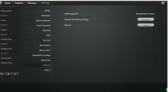
5.11System:
Online Upgrade: If you have the latest software, there will be tips <Update> click update, the camera will be online software upgrade, after the upgrade is successful will re-start the Camera.
Restore the factory settings: The user can click the "Restore" button, will pop up on the right
Diagram tips. When the "Save network device" checked, the point is determined, in addition to
When the "Save Network Device" is not checked, the point is determined, all camera parameters
Few are restored to factory settings back, equivalent to click the RESET button. Reboot: Click the reset button after the restart of the camera.
5.12 Other:
Audio:
Speaker: Set the size of the camera's speaker sound, use the mouse to drag the slider to set, the greater the value, the greater the sound from the speaker.
Mac: Sets the camera microphone sensitivity, drag the slider with the mouse settings, the greater the value, the more sensitive the microphone receiving
sound external environment more, the computer listens to the voice of the larger end, the corresponding listening to ambient noise is greater.
Flip:
To turn upside down.Power Frequency: 50Hz and 60Hz with two frequencies selected the user machine installation area under power frequency to choose.
Click Apply to save your changes.
6. Troubleshooting
This chapter provides solutions for questions or problems in camera installation and operation.
If you encounter problems, please follow solutions below. (Below we take Windows ® Vista ™ and XP as example. Different operation systems have the similar operation.)
1). what is Remote Access? How to do that?
Remote access means that you can access a camera from a web on any PC trough internet. So even if you are not at home, you can access a camera, view live video and manage its settings.
If your camera does not work, please check whether the following things are right.
....STATE2 ( ) on the camera flashes green 3 times every 3 seconds ....Internet connection is working properly
... The router's LAN & WAN connection are working properly. ... Router UPNP and DHCP are on
... Routers can get a public IP.
... Router has been upgraded to the latest firmware version
... Restore your camera to factory settings by press “RESET” key one time on camera bottom
... Disconnect router power supply and connect it again to restart Try again to make your camera work after the above checking. 2). Why is network connection unstable?
Network cable may get a problem. You can PING the address of a existing device in the same network. If network cable connects right and network connect right, you should get a reply like bytes = 32 time = 2 ms.
Another possibility is that the network equipments like hubs and switches may have problems. Ensure all network equipments connect and work well.
This may be caused by firewall protection (such as MAC addresses filtering, MAC address binding with the IP address). In this situation, please contact your system administrator to check firewall. Firewall may need some configuration changes. For more information, please refer to camera installation.
Ensure STATE1 ( ) or STATE2 ( ) flashes 3 times every 3 seconds. Router default settings may have a problem. Ensure router DHCP server is on. If there are multi-level routers, each should connect the other trough WAN (for example, the 1rs router LAN connects the 2ndrouter LAN by a network cable). If
problem still exists, connect your camera with power, and then press “RESET” key on the bottom to restore to factory settings.
4). Why are there vertical white lines in image?
CMOS sensor being exposed to strong light (such as direct exposure to sunlight or halogen light) may cause this problem. CMOS sensor is behind the lens. It is to measure the optical signal and converts it to a digital format, then the
computer will convert digital format to images to users. If the CMOS sensor has been in high night for a long time remember not to move it to dark places for it may damage the sensor.
5). Blur image. What to do?
Or, your camera does not focus properly. Rotate the lens till you see a clear image.
Web viewing on a computer may get a blur image. Because a computer has much larger screen than a phone, and same resolution image will be amplified. 6). Image quality is poor, how to improve it?
Open www.mipcm.com and login. Find image quality configuration to adjust the parameters to improve image quality (e.g.: brightness, contrast, color saturation). 7). When I view on a web, there is no image. Why?
If you are using Internet Explorer, please make sure ActiveX is on. You may need to modify the browser's security settings to allow ActiveX plug-in installed. If you are using Internet Explorer versions earlier than 7.0, you need to upgrade your Web browser.
8). Troubleshooting, LED status indication:
Indicator LED status
Status Description Troubleshooting POWER
(power indicator)
Red light
Normally on
Power supply is normal
If light is not lit, check the power supply is damaged or the camera hardware failure, requiring repair.
STATE1/STA1
( ) (OFF
Wifi was disabled by the user or wifi hardware failure
1. Press RESET for 5 seconds to restore the factory settings.
2.Make camera with wired Ethernet connection, after landing, in the "Manage" -> "Network" ,make WIFI enabled;
3. Camera hardware failure, requiring repair.
Red light
Normally on
WIFI router is trying to connect
1. Verify WIFI router is good;
2. Try the camera placed from somewhere near WIFI router and then reconnect the power.
3.Restart WIFI routers and cameras; 4. Camera hardware failure, requiring repair.
Red Flashing 2
times
Is connected to the router, is trying to obtain an IP address through DHCP
1. Please make sure your router's DHCP server is enabled.
2. Try to restart the router.
3. Manually assign a WIFI router to the same gateway IP address.
Red light flashing 3
times
Ip address has been obtained or the user to configure a static ip address, is trying to communicate with the gateway
1. Confirm the router is good.
2. Camera hardware failure, requiring repair. Green light Normally on And gateway communication is normal, is trying to communicate with the internet
1. User can check whether the network can access the Internet. 2. Check whether there are two routers connected (first level router network cable will need to receive a second-class router's WAN port on the job).
3. Try the camera placed from somewhere near WIFI router and then reconnect the power.
Green flashing 2
times
Internet traffic is normal, is trying to communicate with the cloud server
1. Restart the machine or the machine on again to restart.
2.Try running the camera, based
on the press camera base RESET button hole 6 seconds, set the camera to restore the factory setting. Green light flashing 3 times Normal communication with the cloud server, you can access the camera via cloud services Normal Red\ green lights flashing alternately
Wi-Fi for adhoc mode (Wi-Fi did not
configure the router / router connection failed / DHCP fails to enter this mode), you can Wi-Fi terminal (mobile phone / pad / notebook computers) connected to the wireless network, and then access the camera through 192.168.188.254.
References Cloud Camera Quick Installation Guide
STATE2/STA2
( ) (OFF
Ethernet is disabled by the user or the network cable is not connected or Ethernet card hardware failure
1. Users press RESET 5 seconds to restore the factory settings.
2. Check \ replace the camera and connect the network cable between the routers.
3. Camera hardware failure, requiring repair.
Red light
Network cable is connected, the IP address is obtained
1. Please make sure your routers DHCP server is enabled.
2. Try to restart the router.
3.Manually assign a letter to the Ethernet IP address of the router the same gateway.
Flashing red
IP address has been obtained or the user to configure a static IP address, is trying to communicate with the gateway
1. Confirm whether the router is good. 2.Camera hardware failure, requiring repair.
Green light
And gateway communication is normal, is trying to communicate with the internet
1. The user to check whether the network can access the Internet. 2. Check whether there are two routers connected (first level router network cable will need to receive a second-class router's WAN port on the job).
3. Check the router is turned on the firewall to do MAC address filtering.
Green flashing 2
times
Internet traffic is normal, is trying to communicate with the cloud server
1. Restart the machine or the machine on again to restart. 2.Try running the machine, based on the press machine base RESET button hole 6 seconds, set the machine to restore the factory tune.
Green light flashing 3
Normal
communication with the cloud server, you can access the
Red\ green lights flashing alternately
DHCP fails, use a temporary IP address 192.168.187.254, Users can access the same computer and web cam LAN, set different segments IP (192.168.187.xxx), and then access the camera through 192.168.187.254
References << >> Cloud Camera Quick Installation Guide.
7
.
Wireless Infrastructure
IP CAMERA wireless products are based on industry standards for your home, business or public access wireless networks to provide easy and compatible high-speed wireless connection. IP CAMERA strictly follows the IEEE standard. Wireless LAN (WLAN) is network that transmits and receives data trough wireless signal not electrical wiring. WLAN is increasingly used in home, office, airport, coffee shop, and other public places. WLAN needs no electrical wiring or other base equipments. It helps people to work and communicate easier and more efficient with its mobility.
When you use a wireless network, please note the following: Put your router or access point at center area
Put the router / access point at the highest point of the room, so the signal can be distributed to whole room space. If you have a two-story house, you need to install a repeater to extend signal coverage.
Eliminate interference
Make sure home appliances such as cordless telephones, microwaves, and televisions are far from the router / access point, which helps reduce
interface. Safety
Prevent your next door neighbors or others connecting to your wireless network. Open WPA or WEP in the router to protect your wireless network. Please refer to the product manual for more information on this feature.
8. Wireless Security
This section introduces different levels of security to protect your data from invasion.
IPCAM provides the following security types: • WPA-PSK (pre-shared key)
• WEP (Wired Equivalent Privacy)
What is WEP?
WEP is Wired Equivalent Privacy. It is based on the IEEE 802.11 standard and uses the RC4 encryption algorithm. WEP provides security by data
encryption on your wireless network, so that to ensure secure transitions from one wireless device to the other.
To access a WEP network, you must know the key. Key is a code string. When using WEP, you must specify the level of encryption. Type of encryption determines the key length.128-bit encryption requires a longer key than 64-bit encryption. Key id defined by HEX (16 hex -0-9, AF) or ASCII (American Standard Code for Information Interchange - alphanumeric characters) format. ASCII format allows you to enter a string that is easy to remember. ASCII is converted into HEX when used on the internet. Four keys can be defined for easy changing if needed.
What is WPA?
WPA or Wi-Fi Protected Access is a Wi-Fi standard, designed to improve WEP (Wired Equivalent Privacy) security features.
There are two major improvements over WEP:
It improved data encryption through the Temporal Key Integrity Protocol (TKIP). TKIP messes the keys using a hash algorithm, and ensures that the keys are not changed by adding integrity-checking feature. Based on 802.11i, WPA2 replaces TKIP with Advanced Encryption Standard (AES) instead of TKIP.
User authentication through EAP gets missed in WEP.WEP is easily to be sniffed or stolen for it accesses wireless network trough computer MAC address. EAP is built on a more secure public key encryption system to ensure that only authorized network users can access the network.
WPA-PSK/WPA2-PSK uses a pass phrase or key to authenticate your wireless connection. Key is an alpha-numeric password between 8 and 63 characters long. Password can include symbols and spaces. This key must be the same with your wireless router key or access point key.
After camera installation as the Quick Installation guides, you can use the assigned IP address of the camera. Because you share the same network with
one or more computers trough a router, the assigned IP address is a local address. Then you can view your camera in local network.