Abstract— The demand for high-speed mobile wireless communications is rapidly growing. Orthogonal Frequency Division Multiplexing (OFDM) has become a key element for achieving the high data capacity and spectral efficiency requirements for wireless communication systems because of it multicarrier modulation techniques. But its main drawback is the effect of carrier frequency offset (CFO) produced by the receiver local oscillator or by Doppler shift. This frequency offset breaks the orthogonality among the subcarriers and hence causes intercarrier interference (ICI) in the OFDM symbol, which greatly degrades the overall system performance. In this paper we will study the effects of CFO upon signal to noise ratio (SNR) for an OFDM system, and also estimate the amount of carrier frequency offset. We compare three methods to combat carrier frequency offset: Time domain CP based method, frequency domain based Moose and Classen method. The improved performance of the present scheme is confirmed through extensive MATLAB simulation results.
Index Terms—Carrier Frequency Offset (CFO), Cyclic Prefix (CP), Intercarrier Interference (ICI), Orthogonal Frequency Division Multiplexing (OFDM).
I. INTRODUCTION
Orthogonal frequency division multiplexing (OFDM) is becoming the chosen multi-carrier modulation technique for wireless and multimedia communication systems. Multimedia wireless services require high-bit-rate transmission over mobile radio channels [1]. OFDM can provide large data rates with sufficient robustness to radio channel impairments. Because of high capacity transmission of OFDM, it has been applied to digital transmission system, such as digital audio broadcasting (DAB) system, digital video broadcasting TV (DVB-T) system, asymmetric digital subscriber line (ADSL), ultra-wideband (UWB) system [2], IEEE 802.11a/g Wireless Local Area Network (WLAN), IEEE 802.16 Worldwide Interoperability for Microwave Access (WiMax) systems and HIPERLAN2 (High Performance Local Area Network) [5]. Its application in mobile communication is more complex especially because of the mobility of the mobile user; thus more exact symbol timing and frequency-offset control must be used to ensure that sub-carriers remain orthogonal [3].
Manuscript received April, 2012.
Sandeep Kaur, University College of Engineering, Punjabi University Patila. Patiala, India, 9815206662,
Harjinder Singh, University College of Engineering, Punjabi University Patila. Patiala, India, 9779147705,
Amandeep Singh, University College of Engineering, Punjabi University Patila, 9814357652.
The basic principle of OFDM is to split a high rate data-stream into multiple lower rate data data-streams that are transmitted simultaneously over a number of sub carriers. OFDM uses the spectrum much more efficiently by spacing the channels much closer. This is achieved by making all the carriers orthogonal to one another, preventing interference between the closely spaced carriers. But like other technology OFDM also has its own advantages & disadvantages like [4] High peak to average power ratio (PAPR), Inter-channel/ Symbol interference (ISI/ICI), Sensitive to Doppler Shift & Sensitiveness to frequency synchronization problem. In this paper focus is on frequency offset, which may be caused by Doppler shift in the channel, or by the difference between the transmitter and receiver local oscillator frequencies. This carrier frequency offset causes loss of orthogonality between sub-carriers and the signals transmitted on each carrier are not independent of each other. The orthogonality of the carriers is no longer maintained, which results in inter-carrier interference (ICI). ICI results from the other sub-channels in the same data block of the same user.
ICI problem would become more complicated when the multipath fading is present (X.Cai and Giannakis, 2003). If ICI is not properly compensated it results in power leakage among the subcarriers, thus degrading the system performance. In (Armstrong: 1999), ICI self-cancellation of the data-conversion method was proposed to cancel the ICI caused by frequency offset in the OFDM system. In (Y. Fu, S.G. Kang, and C.C. KO, 2002), ICI self-cancellation of the data-conjugate method was proposed to minimize the ICI caused by frequency offset and it could reduce the peak average to power ratio (PAPR) than the data-conversion method [5]. In (Zhao and S. Häggman, 2001), self ICI cancellation method which maps the data to be transmitted onto adjacent pairs of subcarriers has been described. But this method is less bandwidth efficient [6]. In (van de Beek, Sandell, and Borjesson, 1997), the joint Maximum Likelihood symbol-time and CFO estimator in OFDM systems has been developed. And the CFO only is estimated and is cancelled at the receiver. In addition, statistical approaches have also been explored to estimate and cancel ICI (Tiejun, Proakis, and Zeidler, 2005).
Some techniques are previously developed for reducing the effect of ICI: Frequency offset estimation and compensation techniques, Doppler diversity [2], ICI self cancellation scheme, Frequency domain equalization [7] [9] but it only reduce the ICI caused by fading distortion which is not the major source of ICI. Time Domain Windowing [8] only reduce the ICI caused by band limited channel which is also not the major source of ICI. The major source of ICI in
Carrier Frequency Offset Estimation for
OFDM Systems Using
Time/Frequency-Domain Techniques
OFDM is its vulnerability to frequency offset errors between the transmitted and received signals, which may be caused by Doppler shift in the channel or by the difference between the transmitter and receiver local oscillator frequencies [7]. In this present work, a new carrier frequency offset estimation technique is presented. The proposed scheme cancels CFO in OFDM system and compares their results, which has not been studied previously.
The rest the paper is organized as follows: In section II, OFDM system description has been described. In section III, principle of OFDM transmission technology has been described. In section IV, Estimation techniques for CFO have been described. In section V, simulation results have been analyzed.
II. OFDMSYSTEM DESCRIPTION
OFDM is a combination of modulation and multiplexing. Multiplexing generally refers to independent signals, those produced by different sources. In an OFDM system, the input bit stream is multiplexed into N symbol streams, each with symbol period
𝑇
𝑠, and each symbol stream is used to modulate parallel, synchronous carriers. The sub-carriers are spaced by1 𝑁𝑇
𝑆in frequency, thus they are orthogonal over the interval(0, 𝑇
𝑠)
. A typical discrete-time baseband OFDM transceiver system is shown in Figure 1 which is proposed by B.Sathish Kumar [10]. First, a serial-to-parallel (S/P) converter groups the stream of input bits from the source encoder into groups of log2M bits, where M is the alphabet of size of the digital modulation scheme employed on each sub-carrier. A total of N such symbols, Xm, are created. Then, the N symbols are mapped to bins of an inverse fast Fourier transform (IFFT). These IFFT bins correspond to the orthogonal sub-carriers in the OFDM symbol. Therefore, the OFDM symbol can be expressed as𝑥 𝑛 =
𝑁1 𝑁−1𝑋(𝑚)𝑒
𝑗2𝜋𝑚𝑛 /𝑁𝑚=0 (1)
Where 𝑋 𝑚 ′𝑠 is the baseband symbol on each subcarrier. The digital-to-analog (D/A) converter then creates an analog time-domain signal which is transmitted through the channel.At the receiver, the signal is converted back to a discrete N point sequence y(n), corresponding to each sub-carrier. This discrete signal is demodulated using an N-point fast Fourier transform (FFT) operation at the receiver. The demodulated symbol stream is given by:
𝑌 𝑚 =
𝑁−𝐼𝑛=𝑜𝑦(𝑛)
𝑒
−𝑗 2𝜋𝑛𝑚
𝑁
+ 𝑤(𝑚)
(2)
Where 𝑤(𝑚) corresponds to the FFT of the samples of 𝑤(𝑛) which is the Additive White Gaussian Noise (AWGN) introduced in the channel
Fig. 1: Baseband OFDM transceiver system [10].
III. PRINCIPLE OF OFDM TRANSMISSION TECHNOLOGY
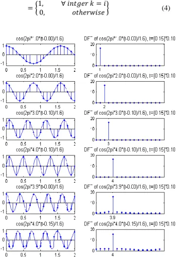
3.1Orthogonaltiy
OFDM is simply defined as a form of multi-carrier modulation where the carrier spacing is carefully selected so that each sub carrier is orthogonal to the other sub carriers. Two signals are orthogonal if their dot product is zero. To check orthogonality, [11] consider the time-limited exponential signals
{𝑒
𝑗2𝜋𝑓𝑘𝑡}
𝑘=0𝑁−1 which represent the different subcarriers at𝑓
𝑘 =𝑘 𝑇
𝑠𝑦𝑚 in the OFDM signal, where0 ≤ 𝑡 ≤ 𝑇
𝑠𝑦𝑚. These signals are defined to be orthogonal if the integral of the dot product over an interval is zero.1
𝑇𝑠𝑦𝑚 𝑒
𝑗2𝜋𝑓𝑘𝑡 𝑇𝑠𝑦𝑚
0
𝑒−𝑗2𝜋𝑓𝑖𝑡𝑑𝑡
= 𝑇1
𝑠𝑦𝑚 𝑒
𝑗2𝜋 𝑘 𝑇𝑠𝑦𝑚𝑡 𝑇𝑠𝑦𝑚
0 𝑒
−𝑗2𝜋 𝑖 𝑇𝑠𝑦𝑚𝑡 𝑑𝑡
= 1
𝑇𝑠𝑦𝑚 𝑒
𝑗2𝜋(𝑘−𝑖)𝑇 𝑠𝑦𝑚𝑡 𝑇𝑠𝑦𝑚
0 𝑑𝑡
= 1, ∀ 𝑖𝑛𝑡𝑔𝑒𝑟 𝑘 = 𝑖0, 𝑜𝑡𝑒𝑟𝑤𝑖𝑠𝑒 (3)
The equation (3) can be written as in the discrete time
domain at sampling instances
𝑡 = 𝑛𝑇
𝑆= 𝑛𝑇
𝑠𝑦𝑚𝑁, 𝑛 = 0,1,2 … … , 𝑁 − 1
.
1
𝑁 𝑒
𝑗2𝜋 𝑘 𝑇𝑠𝑦𝑚𝑛𝑇𝑠 𝑁−1
𝑛=0 𝑒−𝑗2𝜋
𝑖 𝑇 . 𝑛𝑇𝑠 =
1
𝑁 𝑒
𝑗2𝜋 𝑘 𝑇𝑠𝑦𝑚 .
𝑛𝑇 𝑁 𝑁−1
𝑛=0 𝑒
−𝑗2𝜋 𝑖 𝑇𝑠𝑦𝑚 .
𝑛𝑇 𝑠𝑦𝑚 𝑁
= 1
𝑁 𝑒
𝑗2𝜋(𝑘−𝑖)𝑁 𝑛 𝑁−1
= 1, ∀ 𝑖𝑛𝑡𝑔𝑒𝑟 𝑘 = 𝑖0, 𝑜𝑡𝑒𝑟𝑤𝑖𝑠𝑒 (4)
Fig. 2: Sinusoidal signals with different frequencies/phase and their DFTs.
The above orthogonality is an essential condition for the OFDM signal to be ICI free.
IV. ESTIMATIONTECHNIQUESFORCFO CFO estimation can also be obtained by the exploitation of the inherent structure of OFDM signals [12]. But works presented in this paper concentrate on a Carrier Frequency offset estimation using frequency and time-domain techniques.
4.1.1 CFO Estimation Techniques Using Cyclic Prefix (CP): With perfect symbol synchronization, a CFO of 𝜀 results in a phase rotation of 2𝜋𝑛𝜀 𝑁 in the received signal. Under the assumption of negligible channel effect, the phase difference between CP and the corresponding rear part of an OFDM symbol caused by CFO 𝜀 is 2𝜋𝑁𝜀 𝑁 = 2𝜋𝜀. Then, the Then, the CFO can be found from the phase angle of the product of CP and the corresponding rear part of an OFDM symbol, for example 𝜀 = 1 2𝜋 arg 𝑦𝑙∗ 𝑛 𝑦𝑙 𝑛 + 𝑁 ,
−1, −2, … … − 𝑁𝑔. In order to reduce the noise effect, its
average can be taken over the samples in a CP interval as
𝜀 = 1
2𝜋𝑎𝑟𝑔 𝑦𝑙∗ 𝑛 𝑦1[𝑛 + 𝑁]
−1
𝑛=−𝑁𝐺
(7)
Since the argument operation arg ( ) is performed by using
tan−1( )
, the range of CFO estimation in equation (7) is
[−𝜋, +𝜋) 2𝜋 = [0.5, +0.5) so that 𝜀 ≤ 0.5 and
consequently, integral CFO cannot be estimated by this technique.
This [𝑦𝑙∗ 𝑛 𝑦𝑙 𝑛 + 𝑁 becomes real only when there is no
frequency offset. This implies that it becomes imaginary as long as the CFO exists. In fact, the imaginary part of [𝑦1∗ 𝑛 𝑦1 𝑛 + 𝑁 can be used for CFO estimation [13]. In
this case, the estimation error is defined as
𝑒𝜀=
1
𝐿 𝐼𝑚 𝑦𝑙∗ 𝑛 𝑦1[𝑛 + 𝑁] 𝐿
𝑛=1
(8)
Where L denotes the number of samples used for averaging. Note that the expectation of the error function in Equation (8) can be approximated as
𝐸 𝑒𝜀 = 𝜎𝑁𝑑 2
sin(2𝜋𝜀𝑁 )
𝐻𝑘2 𝐿
𝑘 𝑐𝑟𝑜𝑠𝑝𝑜𝑛𝑑𝑖𝑛𝑔 𝑡𝑜 𝑢𝑠𝑒𝑓𝑢𝑙 𝑐𝑎𝑟𝑟𝑖𝑒𝑟𝑠 ≈ 𝐾𝜀 (9)
Fig 3: Characteristic curve of the error function Equation (9).
Where
𝜎𝑑2 is the transmitted signal power, 𝐻𝑘 is thechannel frequency response of the 𝑘𝑡 subcarrier, and K is a term that comprise transmit and channel power. Figure 3 show that the error function in equation (9) has an S-curve around the origin, which are required for synchronization. This particular approach also provides 𝜀 as with equation (7).
domain, which can be generated by taking the IFFT of a comb-type signal in the frequency domain given as
𝑋𝑙 𝑘 =
𝐴𝑚, 𝑖𝑓 𝑘 = 𝐷. 𝑖, 𝑖 = 0,1 … … , (𝑁 𝐷 − 1
0 𝑜𝑡𝑒𝑤𝑖𝑠𝑒
(10)
Where 𝐴𝑚 represents an M-ary symbol and 𝑁 𝐷 is an
integer. As 𝑥𝑙[𝑛] and 𝑥𝑙[𝑛 + 𝑁 𝐷] are identical (i.e.,
[𝑦1∗ 𝑛 𝑦1 𝑛 + 𝑁 𝐷 = 𝑦𝑙[𝑛] 2𝑒𝑗𝜋𝜀, a receiver can make
CFO, estimation as follows [14] [15].
𝜀 = 𝐷
2𝜋𝑎𝑟𝑔 𝑦𝑙∗ 𝑛 𝑦1[𝑛 + 𝑁 𝐷 ]
𝑁 𝐷−1
𝑛=0
(11)
The CFO estimation range covered by this technique is 𝜀 ≤ 𝐷 2 .Which becomes wider as D increases. Note that the number of samples for the computation of correlation is reduced by 1/D, which may degrade the MSE performance. In other words, the increase in estimation range is obtained at the sacrifice of MSE (mean square error) performance. Figure 4 shows the estimation range of CFO vs. MSE performance for D=1 and 4.Here, a trade-off relationship between the MSE performance and estimation range of CFO is clearly shown. As the estimation range of CFO increases, the MSE performance becomes worse. By taking the average of the estimates with the repetitive patterns of the shorter period as
𝜀 = 𝐷
2𝜋𝑎𝑟𝑔 𝑦𝑙∗ 𝑛 + 𝑚𝑁 𝐷
𝑁 𝐷−1
𝑛=0 𝐷−2
𝑚=0
𝑦1[𝑛 + (𝑚
+ 1) 𝑁 𝐷 ] (12)
The MSE performance can be improved without reducing the estimation range of CFO.
4.2 Frequency-Domain Estimation Techniques for CFO 4.2.1 CFO Estimation Techniques Using Moose method:
If two identical training symbols are transmitted consecutively, the corresponding signals with CFO of e are related with each other as follows:
𝑦2 𝑛 = 𝑦1 𝑛 𝑒𝑗2𝜋𝑁𝜀 𝑁 ↔ 𝑌2 𝑘 = 𝑌1[𝐾]𝑒𝑗2𝜋𝜀 (13)
Using the relationship in equation (13), CFO can be estimated as
𝜀 = 1
2𝜋tan−1 𝐼𝑚[𝑦1∗ 𝑘 𝑦2 𝑘 ] 𝑅𝑒[
𝑁−1
𝑘=0 𝑁−1
𝑘=0
𝑦1∗ 𝑘 𝑦2[𝑘]] (14)
This is a well-known approach by Moose [16]. Although the range of CFO estimated by Equation (14) is 𝜀 ≤
𝜋 2𝜋 = 1 2,it can be increased D times by using a training symbol with D repetitive patterns. The repetitive patterns in the time-domain signal can be generated by Equation (10).
In this case, Equation (14) is applied to the subcarriers with non-zero value and then, averaged over the subcarriers. As discussed in the previous subsection, the MSE performance may deteriorate due to the reduced number of non-zero samples taken for averaging in the frequency domain. Note that this particular CFO estimation technique requires a special period, usually known as a preamble period, in which the consecutive training symbols are provided for facilitating the computation in Equation (14).
Fig 4: Estimation range of CFO vs. MSE performance [10].
In other words, it is only applicable during the preamble period, for which data symbols cannot be transmitted.
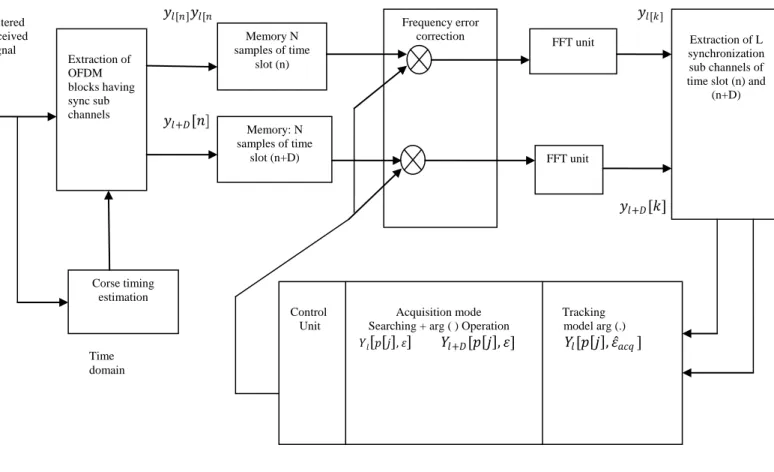
4.2.2 CFO Estimation Techniques Using Classen method: As proposed by Classen [17], pilot tones can be inserted in the frequency domain and transmitted in every OFDM symbol for CFO tracking. Figure 5 shows a structure of CFO using pilot tones. First, two OFDM symbols, 𝑦𝑙[𝑛]
and 𝑦𝑙+𝐷 𝑛 , are saved in the memory after synchronization.
Then, the signals are transformed into{𝑌𝑙 𝑘 }𝐾=0𝑁−1and
{𝑌𝑙+𝐷[𝑘]}𝐾=0𝑁−1 via FFT, from which pilot tones are extracted.
After estimating CFO from pilot tones in the frequency domain, the signal is compensated with the estimated CFO in the time domain. In this process, two different estimation modes for CFO estimation are implemented: acquisition and tracking modes. In the acquisition mode, a large range of CFO including an integer CFO is estimated. In the tracking mode, only fine CFO is estimated. The integer CFO is estimated by
𝜀 𝑎𝑐𝑞 = 1
2𝜋.𝑇𝑆𝑢𝑏𝑚𝑎𝑥 𝑌𝑙+𝐷 𝐿−1
𝑗 =0 𝑝 𝑗 , 𝜀 𝑌𝑙∗ 𝑝 𝑗 , 𝜀 𝑋𝑙+𝐷∗ 𝑝 𝑗 𝑋𝑙 𝑝 [𝑗]]
(15) Where𝐿, 𝑝[𝑗] and 𝑋𝑙 𝑝 𝑗 denote the number of pilot tones,
the location of the 𝑗𝑡 pilot tone, and the pilot tone located at
𝜀 =𝑓
1
2𝜋. 𝑇𝑠𝑢𝑏𝐷𝑎𝑟𝑔
𝑌𝑙+𝐷 𝐿−1
𝑗 =0
𝑝 𝑗 , 𝜀 𝑎𝑐𝑞 𝑌𝑙∗ 𝑝 𝑗 , 𝜀 𝑎𝑐𝑞
𝑋𝑙+𝐷∗ 𝑝 𝑗 𝑋𝑙 𝑝 [𝑗]]
the CFO is compensated by their sum. In the tracking mode, only 𝜀 𝑓is estimated and then compensated.
Figure5: CFO synchronization scheme using pilot tones
V. SIMULATATIONRESULT
Table 1.
Parameter Specifications
FFT Size 128
Modulation Scheme QAM
Frequency offset 0.03, 0.15
Guard length 32
Channel AWGN
Number of bits per symbol 2
Symbol Duration 3
Number of Carriers in OFDM symbol
160
MSE performance of proposed system is compared by using ―CFO-CP‖, Moose and Classen method in Figure 6 (a-b) at different frequency offset values. Simulation have been performed by considering system parameters as FFT Size 128, with QAM modulation technique considering additive white Gaussian (AWGN) channel as shown in table 1. Figure 5(a) shows that the mean squared CFO estimation errors decrease as the SNR of the received signal increases. Performances of estimation techniques vary depending on the number of samples in CP, the number of samples in preamble, and the number of pilot tones, used for CFO estimation.
Extraction of OFDM blocks having sync sub channels
Memory N samples of time
slot (n)
Memory: N samples of time
slot (n+D)
Frequency error correction
FFT unit
FFT unit
Extraction of L synchronization sub channels of time slot (n) and
(n+D)
Corse timing
estimation
𝑌𝑙 𝑝𝑗, 𝜀 𝑌𝑙+𝐷[𝑝 𝑗 , 𝜀] 𝑌𝑙[𝑝 𝑗 , 𝜀 𝑎𝑐𝑞] 𝑌𝑙[𝑝 𝑗 , 𝜀 𝑎𝑐𝑞]
𝑌𝑙+𝐷[𝑝 𝑗 , 𝜀 𝑎𝑐𝑞]
Control Acquisition mode Tracking Unit Searching + arg ( ) Operation model arg (.)
𝑌𝑙+𝐷[𝑝 𝑗 , 𝜀] 𝑌𝑙[𝑝 𝑗 , 𝜀 𝑎𝑐𝑞]
Filtered received signal
𝑦𝑙[𝑛]𝑦𝑙[𝑛] 𝑦𝑙[𝑘]
𝑦𝑙+𝐷[𝑛]
𝑦𝑙+𝐷[𝑘]
Frequency domain Time
Fig 6(a): MSE of CFO estimation techniques 𝜀 = 0.03.
(b): MSE of CFO estimation techniques 𝜀 = 0.15
VI CONCLUSION
In this paper, the performance of OFDM systems in the presence of frequency offset between the transmitter and the receiver has been studied in terms of the mean squared error and the signal to noise ratio (SNR) performance. Inter-carrier interference (ICI) which results from the frequency offset between the frequencies of transmitter and the receiver oscillators degrades the performance of the OFDM system. Three methods CFO-CP, Moose and Classen methods were explored in this paper. The choice of which method to employ depends on the specific application. Such a technique will improve the performance of the existing OFDM systems.
ACKNOWLEDGMENT
Sandeep Kaur Author wishes to express her sincere gratitude to Mr. Harjinder Singh, Assistant Professor, University College of Engineering, Punjabi University, Patiala for guiding her throughout the current research work.
REFERENCES
[1] Arvind Kumar, Rajoo Pandey,―A bandwidth-efficient method for cancellation of ICI in OFDM systems,‖ Int. J. Electron. Comm, vol. 63. pp. 569-575, 2009.
[2]Yi-Hao Peng, Ying-Chih Kuo, Gwo-Ruey Lee, Jyh-Horng Wen, Nat. Chung Cheng Univ., Chia-Yi, ―Performance Analysis of a New ICI-Self-Cancellation-Scheme in OFDM Systems,‖ IEEE Trans. vol. 53, pp. 1333-1338 2007.
[3] Shivangi Singh, Santosh Kumar Gupta, Dr. B.S.Rai, ―Performance Evalutions to Remove CFO for Multicarrier Modulatin System,‖ IJECT
Vol. 2, Issue 3, Sept. 2011.
[4] Mitalee Agrawal, Yudhishthir Raut, ―Effect of Guard Period Insertion in MIMO OFDM System, IJCTEE vol 1, Issue 2, 2011.
[5] Haitham J. Taha and M.F.M. Salleh, ―ICI Self-Cancellation for FFT-OFDM System‖ Australian Journal of Basic and Applied Sciences, 4(11): 5621-5629, 2010
[6] Yi-Hao Peng, Ying-Chih Kuo, Gwo-Ruey Lee, Jyh-Horng Wen, Nat. Chung Cheng Univ., Chia-Yi, ―Performance Analysis of a New ICI-Self-Cancellation-Scheme in OFDM Systems,‖ IEEE Trans. vol. 53, pp. 1333 – 1338, 2007.
[7] Shruti M. Kallurwar, Rahila Patel, ―An Experimental Study to Reduce the Effect of ICI in OFDM Based WLAN System,‖ IJCST, vol. 3, Issue 1, March 2012.
[8] Ze Zhu, Xiang Tang, JiZhang Zuo,―Self-Cancellation Method of OFDM ICI,‖ IEEE Trans. pp. 1-5, 2008.
[9] Yuping Zhao and Sven-Gustav Häggman, ―Intercarrier Interference Self-Cancellation Scheme,‖ IEEE Trans. vol.49, July 2001.
[10] B.Sathish Kumar, K.R.Shankar Kumar, R.Radhakrishnan,―An Efficient Inter Carrier Interference Cancellation Schemes for OFDM Systems,‖ IJCSIS, vol.6, 2009.
[11] Yong Soo Cho, Jaekwon Kim,Won Young Yang,Chung-Gu Kang, ―MIMO-OFDM wireless communications with MALAB,‖ John Wiley & Sons (Asia) Pte Ltd., 2010.
[12] Defeng (David) Huan, Khaled Ben Letaief,, ―Carrier Frequency Offset Estimation for OFDM Systems Using Null Subcarriers,‖ IEEE Trans. vol 54, May 2006.
[13] Daffara, F. and Adami, O, ―A new frequency detector for orthogonal multi-carrier transmission techniques,‖ IEEE VTC’95, pp. 804-809 July 1995.
[14] Schmidl, T.M. and Cox, D.C., ―Robust frequency and timing synchronization for OFDM,‖ IEEE Trans. vol 45(12), 1613–1621 1997. [15] Taura, K., Tsujishta, M., Takeda, M. et al, ―A digital audio broadcasting (DAB) receiver,‖ IEEE Trans. Consumer Electronics, vol. 42(3), 322-326 1996.
[16] Moose, P.H. (1994)Atechnique for orthogonal frequency division multiplexing frequency offset correction. IEEE Trans. Commun., vol.42, 2908-2914, 1994.
[17] Classen, F. and Myer, H, ―Frequency synchronization algorithm for OFDM systems suitable for communication over frequency selective fading channels,‖ IEEE VTC’94, pp. 1655–1659, June 1994.
[18] Cai, X. and G.B. Giannakis, ―Bounding performance and suppressing intercarrier interference in wireless mobile OFDM,‖ IEEE Trans. on communications, 51(12): 2047-2056, 2003.
[19] Armstrong, J, ―Analysis of new and existing methods of reducing intercarrier interference due to carrier frequency offset in OFDM‖, IEEE Trans. on Communications, 47 (3) 365-369, 1999.
[20] Fu, Y., S.G. Kang and C.C. KO, ―A new scheme for PAPR reduction in OFDM systems with ICI self cancellation,‖ in Proc. VTC 2002-Fall,
IEEE 56th Vehicular Technology Conf., 3: 1418-1421, 2002.
[21] van J.-J. de Beek, M. Sandell and P.O. Borjesson, ―ML estimation of time and frequency offset in OFDM systems,‖ IEEE Trans. Signal Process., 45: 1800-1805, 1997.
systems,‖ Wireless Communications and Networking Conference, IEEE
Volume 1, Issue, 13-17(1): 39-44, 2005.
[23] Ramjee Prasad, ―OFDM for wireless communication system‖,Artech House, 2004.
[24] Theodore S. Rappaport, Wireless Communications Principles and Practice, 2nd ed. Dec 31, 2001.
[25] Adarsh B.Narasimhamurthy, Mahesh K.Banavar and Cihan Tepedelenliogu,―OFDM system for wireless communications.
[26] Uma Shanker, Jha Rajmee Prasad, ―OFDM towards Fixed and Mobile Broadband Wireless Access‖, 3 OCT 2012.
Authors:
Sandeep Kaur: Miss. Sandeep Kaur is currently pursuing M.TECH (final year) in department of Electronics and Communication Engineering at University College of Engineering, Punjabi University, Patiala. She has done her B.TECH. in trade electronics and communication engineering from Yadavindra College of Engineering, Punjabi University, Patiala. She has presented many papers in national and international conferences. Her topic of research is intercarrier interference in orthogonal frequency division multiplexing systems.
Harjinder Singh: Harjinder Singh is currently Assistant Professor at University College of Engineering, Punjabi University, Patiala, India. He has completed his B.Tech & M.Tech. from Guru Nanak Dev Engineering college Ludhiana , Punjab, India. Mr. Harjinder has 14 years of academic experience. His areas of interest are Wireless communication, Signal processing, Optical communication. He has to his credit many papers in international journals and national and international conferences.
![Fig. 1: Baseband OFDM transceiver system [10].](https://thumb-us.123doks.com/thumbv2/123dok_us/8105676.2148875/2.893.466.855.139.398/fig-baseband-ofdm-transceiver-system.webp)
![Fig 4: Estimation range of CFO vs. MSE performance [10].](https://thumb-us.123doks.com/thumbv2/123dok_us/8105676.2148875/4.893.467.830.281.576/fig-estimation-range-cfo-vs-mse-performance.webp)