www.ijseat.com Page 515
A New Efficient Approach for Melioration of Power Quality in
Grid Interfacing with PV/Battery Hybrid System
VAIBHAV KUMAR VEMULA
PG scholar, Dept of EEE
Balaji institute of Technology & Science, JNTUH,
Warangal, Telangana, India
MALLIKARJUN REDDY S
Associate professor, HOD, Dept of EEE Balaji Institute of Technolgy & Science,
JNTUH,
Warangal, Telangana, India
Abstract:— This paper proposes grid integration of solar (PV)/Battery hybrid energy conversion system with (i) multi-functional features of micro grid-side bidirectional voltage source converter (μG-VSC) (ii) tight voltage regulation capability of battery converter (iii) MPPT tracking performance of high gain integrated cascaded boost (HGICB) dc-dc Converter with quadratic gain and less current ripple. The PV side HGICB Converter is controlled by P&O MPPT algorithm to extract the maximum power from the variable solar irradiation. This paper proposes a modified Instantaneous symmetrical components theory to the μG-VSC in micro-grid applications with following intelligent functionalities (a) to feed the generated active power i n proportional to irradiation levels into the grid (b) compensation of the reactive power, (c) load balancing and (d) mitigation of current harmonics generated by non-linear loads, if any, at the point of common coupling (PCC), thus enabling the grid to supply only sinusoidal current at unity power factor. The battery energy storage system (BESS) is regulated to balance the power between PV generation and utility grid. A new control algorithm is also proposed in this paper for the battery converter with tight DC link voltage regulation capability. The dynamic performance of battery converter is investigated and compared with conventional average current mode control (ACMC). The effectiveness of the proposed control strategies for HGICB converter and μG-VSC with battery energy conversion system are verified through MATLAB/SIMULINK results.
I. I
NTRODUCTIONHybrid plants, which are composed of combinations of diesel generators, battery energy storage system and renewable energy resources such as photovoltaic, are outlined as a recommended approach for off grid power supply options for remote areas applications. The PV source is a nonlinear renewable energy source and direct connection of load will not give optimum utilization of the PV system. In order to utilize the PV source optimally, it is necessary to provide an intermediate electronic controller in between
source and load under all operating conditions. Using this electronic controller it is possible to operate the PV source at maximum power point (MPP), thus improving the energy efficiency of the PV system [1-2].
Many control algorithms have been reported in the literature to track maximum power from the PV arrays, such as incremental conductance (INC), constant voltage (CV), and perturbation and observation (P&O). The two algorithms often used to achieve maximum power point t racking are the P&O and INC methods. Many DC-DC converter topologies are available to track the MPP in PV generating system. Cascade connection of conventional converters provides wider conversion ratios. One of the major advantages of these converters is a high gain and low current ripple. However, this configuration has a drawback that the total efficiency may become low if the number of stages are high, owing to power losses in the switching devices [2-4].
A quadratic converter configuration is also available that uses single switch and achieves quadratic gain. An interesting attractive converter topology is a high gain integrated cascaded boost converter having n-converters connected in cascade using a single active switch. The instability caused by the cascade structure is avoided, when compared with the conventional cascade boost converter. This class of converters can be used only when the required number of stages is not very large, else the efficiency will be reduced. However, this class of converters for PV applications are not reported in the technical literature. Micro-grid power converters can be classified into (i) grid-feeding, (ii) grid-supporting, and (iii) grid-forming power converters [4-5].
www.ijseat.com Page 516
control strategies mentioned above, the Instantaneous symmetrical component based control proposed in this paper for micro-grid applications is simple in formulation [5-7]. The effectiveness of the proposed control strategies for HGICB converter and μG-VSC with battery energy conversion system are verified through MATLAB/SIMULINK results. Finally, an economical overview is performed by considering the difference of fuel consumption between the proposed control strategies.
II. H
YBRIDE
NERGYC
ONVERSIONS
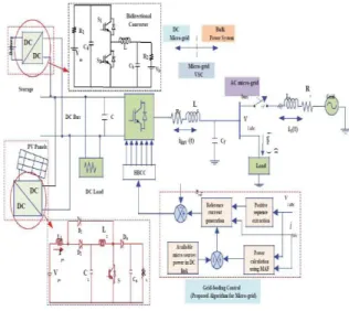
YSTEMFig. 1. shows the proposed Hybrid Energy Conversion System (HECS) consists of a PV/Battery hybrid system with the main grid connecting to non-linear and unbalanced loads at the PCC. The PV array is connected to HGICB dc-dc converter and bidirectional battery converter is shown in Fig. 1, which is coupled at the dc side of a μG-VSC. The HGICB dc-dc converter is connected to the PV array works as MPPT controller and battery converter is used to regulate the power flow between dc and ac side of the system.
Fig. 1. Proposed HECS model
III. A
NALYSIS ANDM
ODELING The MPPT algorithm for HGICB Converter, control approaches for battery converter and μG-VSC are discussed in the following sections.A. Modeling of PV Array
General mathematical model of PV system is used in this thesis.
B. Modeling Battery Converter
The battery converter goes through two topological stages in each switching period, its power stage dynamics can be described by a set of state equations. The average state space model of the converter given as:
(1)
The averaged model is nonlinear and time-invariant because of the duty cycle, d(t). This model
is finally linearized about the operating point to obtain a small-signal model is shown in Fig. 4. The following are the important transfer functions used to design the compensators and to analyze the system behavior under small signal conditions (i) the duty-cycle-to-output transfer function Gcv (s),
carries the information needed to determine the type of the voltage feedback compensation,(ii) the duty-cycle-to-inductor current transfer function
Gci(s), is needed to determine the current controller
structure.
C. Battery Converter Control
If AC side of μG-VSC has constant power appliances (CPAs), in the small-signal sense, CPAs nature leads to negative incremental input-conductance which causes destabilization of the dc-link voltage. On the micro grid generation side, the inherent negative admittance dynamics of their controlled conversion stages challenges the dc-link voltage control and stability.
www.ijseat.com Page 517
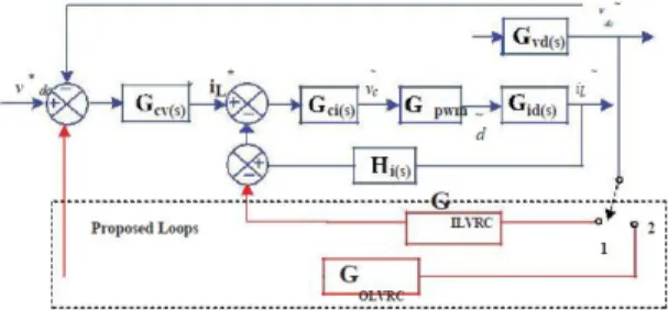
This effect is more with reduced dc-link capacitance. Therefore, in both cases, fast and effective control and stabilization of the dc-link voltage is very crucial issue. To address this problem, many methods are reported in the literature like (i) by large DC link capacitance (ii) by adding passive resistances at various positions in DC LC filter (iii) by loop cancellation methods. In this paper, a new modified – ACMC (MACMC) control algorithm is proposed for effective control and stabilization of battery converter by introducing virtual resistance (VR) in the (i) outer loop called outer loop virtual resistance control (OLVRC) (ii) intermediate loop called inner loop virtual resistance control (ILVRC) as shown in Fig. 2. The proposed virtual resistance based dynamic damping methods aim at injecting a damping signal that compensate for negative conductance caused by CPAs without any power loss.
D. Design steps for Compensators of BESS
The effectiveness of proposed VRCs control algorithm is investigated and compared with the use of traditional ACMC. The flowchart for modes of operation of battery converter in grid feeding mode is shown in Fig. 3. The design guidelines for inner and outer loop compensators of ACMC are given below.
Fig. 3. Hybrid system flow chart of power flow The inner loop (current) gain can be written as:
The outer loop (voltage) gain can be written as:
and the overall loop gain therefore can be written as:
Voltage Loop Design Steps:
i) Place one zero as high as possible, yet not exceeding resonating frequency of the converter.
ii) Place one pole at frequency of output capacitor ESR to cancel the effects of output capacitor ESR.
iii) Adjust, gain of compensator to trade-off stability margins and closed-loop performance.
iv) Another pole should be place at origin to boost the dc and low frequency gain of the voltage loop.
Similar steps mentioned above are followed to design current loop and for design of MACMC loops. Following the design procedure given above, the inner current and outer voltage loop compensators are designed to regulate the DC link voltage to 920 V.
Fig. 4. Inner and outer loops of battery converter
E. Reference currents generation for μG-VSC
The main aim of the μG-VSC control is to cancel the effects of unbalanced and harmonic components of the local load, while supplying pre-specified amount of real and reactive powers to the load. Upon successfully meeting this objective, the grid current ig will then be balanced and so will be the PCC voltage vp provided, grid voltage vg is balanced. Let us denote the three phases by the subscripts a, b and c. Since ig is balanced, we can write:
From the Fig. 1, Kirchoffs current law (KCL) at PCC gives
www.ijseat.com Page 518
Since ig is balanced due to the action of the compensator, the voltage vp will also become balanced. Hence, the instantaneous real powers Pg will be equal to its average component. Therefore, we can write
IV. S
IMULATIONR
ESULTSMATLAB/SIMULINK model of Hybrid Energy Conversion System is shown in Fig. 5. The proposed control strategies for PV hybrid generating system is developed and simulated using MATLAB/SIMULINK under different solar insolation levels. In order to capture the transient response of the proposed control system, PV insolation is assumed to increase from 200 to 1000 W/m2 at 0.3 s, and decreases from 1000 to 200 W/m2 at 0.5 s. This abrupt increase or decrease is assumed in this work in order to test the robustness of the proposed control algorithm. As a result, the inductor current of the HGICB converter is varied to track the maximum power accordingly and the power flow between the μG-VSC, grid and load is also varied under above the operating conditions.
Fig. 5. Simulink model of proposed HECS
TABLE I SYSTEM PARAMETERS
System Quantities Values
System voltages 325 V peak phase to neutral, 50 Hz
Linear Load Zla = 50 + j1.57 Ω, Zlb = 45 + j3.14 Ω, Zlc = 40 + j4.71 Ω
Non-Linear Load
Three phase full bridge rectifier load feeding a R-L
load of 44Ω-3 mH
G-VSC parameters Cdc=660 μF, Vdcref =920 V, Lf = 5 mH, Rf = 0.1Ω
Hysteresis band 0.25 A
A. HGICB Converter MPPT Performance
The dynamic performance of HGICB converter with P&O MPPT algorithm at two different insolation levels are shown in Fig. 6. A variable PV voltage and current in proportion to insolation levels are applied to HGICB converter and as a result, the duty cycle is calculated using the MPPT algorithm. The PV characteristics at two insolation levels are shown in Fig. 6(a)-(b). From Fig. 6 (a), the maximum power, current and voltage are 2.6 kW, 14 A and 190 V respectively and these values are tracked by HGICB converter which are shown in Fig. 6 (d)-(f). Tracked values of PV power, voltage and currents are given in Table II for the above operating insolation levels. From these results it can be concluded that, HGICB converter is tracking maximum power closely at all operating conditions.
Fig. 6. MPPT Tracking performance of HGICB Converter (a) PV Characteristic at G=200 W/m2
(b) PV Characteristic at G=1000 W/m2 (c) insolation variations (d) PV Maximum Power (e)
PV Current (f) PV Voltage.
TABLE II
MAXIMUM POWER TRACKING PERFORMANCE
Time (s)
G (W/m2)
𝑽𝒑𝒗𝒓𝒆𝒇
(V)
𝑰𝒑𝒗𝒓𝒆𝒇
(A)
𝑷𝒑𝒗𝒎𝒂𝒙
(kW) 0.2-0.3 200 190 14 2.5 0.2-0.5 1000 143 87 12.5
0.5-1 200 190 14 2.5
TABLE III
MAXIMUM POWER TRACKING PERFORMANCE
G (W/m2)
𝑷𝒍𝒐𝒂𝒅
(kW)
𝑷𝒑𝒗
(kW)
𝑷𝒊𝒏𝒗
(kW)
𝑷𝒈𝒓𝒊𝒅
www.ijseat.com Page 519
B. Performance of μG-VSC under different insolation levels
The μG-VSC is actively controlled to inject the generated active power as well as to compensate the harmonic and reactive power demanded by the unbalanced and non-linear load at PCC, such that the current drawn from grid is purely sinusoidal at UPF. The dynamic compensation performance of μG-VSC using proposed control algorithm with insolation change and non linear unbalanced load currents are shown in the Fig. 7 (a)-(d) along with grid side currents.
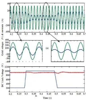
When insolation G = 200 W/m2, the maximum power extracted from PV arrays is 2.5 kW and the total dc load power (4.5 kW) is partly supplied by PV arrays and the remaining dc load power (2 kW) is drawn from grid through the bidirectional μG-VSC. Here observed that the power flows from ac side to dc link as shown in the Fig. 8. When insolation G = 1000 W/m2, the maximum power available from PV arrays is 12.5 kW, part of this power (4.5 kW) is supplied to dc load and remaining power (8 kW) is supplied to the ac load through bidirectional μG-VSC. In this case, the power flows from dc link to ac side. These dynamics of power flows can be seen from Fig. 8. The corresponding variations in the grid current against grid voltage with upf are shown in the Fig. 9, along with dc link voltage variations.
Fig. 7. Performance of proposed control approach for Micro-grid side VSC: (a) Insolation Changes
(b) Load currents (c) Grid currents (d) μG-VSC currents.
C. Performance of battery converter control algorithms with DC load and insolation variations
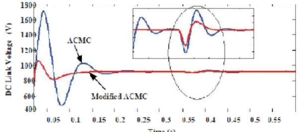
The dynamic performance of ACMC and MACMC proposed in this paper are investigated through (i) DC load variations (ii) insolation changes. At t=0.35 s, the dc load is changed from 4.5 kW to 5.5 kW. Corresponding to these variations, the DC link voltage regulation capability of these two control algorithms are shown in the Fig. 10. From Fig. 10, it can be concluded that for dc load changes, the modified-ACMC gives better DC Link voltage regulation capability when compared to ACMC. The battery performance with reference to above changes are captured and are shown in the Fig. 11.
Fig. 8. Real and Reactive Power flow waveforms of PV hybrid generating system.
Fig. 9. Simulation results: performance of proposed control approach (a) Grid Voltages and currents (b)
www.ijseat.com Page 520
Fig. 10. DC Link Voltage Dynamics using ACMC and MACMC Control algorithms
Fig. 11. Battery performance using proposed control approach to bidirectional battery converter:
(a) Battery Voltage (b) State of charge (SOC) (c) Battery current.
V. C
ONCLUSIONThis paper proposes grid integration of solar (PV)/Battery hybrid energy conversion system. The performance of PV/Battery hybrid energy conversion system has been demonstrated with the application of modified instantaneous symmetrical components theory to μG-VSC proposed in this paper, an efficient control strategy is also proposed for battery converter to regulate the dc bus voltage tightly, under varying solar insolation and dc load conditions. HGICB converter topology is used to track the MPPT with high gain and less current ripple. The system works satisfactorily under dynamic conditions. The simulation results under a unbalanced non-linear load with current THD of 12% confirm that the μG-VSC can effectively inject the generated active power along with power quality improvement features and thus, it maintains a sinusoidal and UPF current at the grid side. The effectiveness of the proposed system verified through MATLAB/SIMULINK results.
R
EFERENCES[1] J. Carrasco, L. Franquelo, J. Bialasiewicz, E. Galvan, R. Guisado, M. Prats, J. Leon, and N. Moreno-Alfonso, ―Power-electronic systems for the grid integration of renewable energy sources: A survey,‖ IEEE Trans. Ind. Electron., vol. 53, no. 4, pp. 1002 –1016, Jun. 2006.
[2] M. de Brito, L. Galotto, L. Sampaio, G. de Azevedo e Melo, and C. Canesin, ―Evaluation of the main mppt techniques for photovoltaic applications,‖ IEEE Trans. Ind. Electron., vol. 60, no. 3, pp. 1156 – 1167, Mar. 2013.
[3] B. Subudhi and R. Pradhan, ―A comparative study on maximum power point tracking techniques for photovoltaic power systems,‖ IEEE Trans. Sustain. Energy, vol. PP, no. 99, pp. 1 –10, Mar. 2012.
[4] W. Li and X. He, ―Review of nonisolated high-step-up dc/dc converters in photovoltaic grid-connected applications,‖ IEEE Trans. Ind. Electron., vol. 58, no. 4, pp. 1239 –1250, Apr. 2011.
[5] J. Rocabert, A. Luna, F. Blaabjerg, and P. Rodri andguez, ―Control of power converters in ac microgrids,‖ IEEE Trans. Power Electron., vol. 27, no. 11, pp. 4734 –4749, Nov. 2012.
[6] R. Kadri, J.-P. Gaubert, and G. Champenois, ―An improved maximum power point tracking for photovoltaic grid-connected inverter based on voltage-oriented control,‖ IEEE Trans. Ind. Electron., vol. 58, no. 1, pp. 66 –75, Jan. 2011.
[7] S. Zhang, K.-J. Tseng, D. Vilathgamuwa, T. Nguyen, and X.-Y. Wang, ―Design of a robust grid interface system for pmsg-based wind turbine generators,‖ IEEE Trans. Ind. Electron., vol. 58, no. 1, pp. 316–328, Jan. 2011.
VAIBHAV KUMAR VEMULA currently pursuing his M.Tech in Electrical Power Systems in Balaji institute of Technology and Sciences, Warangal, Telangana, India affiliated to JNTU University, Hyderabad. He has done his B.Tech degree from Balaji institute of Technology and Sciences, affiliated to JNT University, Hyderabad, Telangana, India in 2012 and his fields of interest include Renewable Energy Sources, Power Systems and Control Systems.