Harmonic Compensation of Distribution generation Using
Photovoltaic Interfacing Inverter
1Thulluri.Shiva,2N.Vijayakumar
1M.Tech(Research scholar),2Assistant professor in Dept. of EEE Godavari Institute of Engg.& Technology
Rajahmundry,A.P,INDIA Abstract:
Normally increasing utilization of electronic devices in homes leads the researchers to concentrate on harmonic problem Besides the degrading power quality, the harmonic current flow may interfere with the adjacent telephone lines. The harmonics in a residential system is difficult because of the dispersed nature of the residential loads.
This worktried to improve the power quality using distributed generation system in residential areas. To compensate a harmonics resonance in residential areas, active and passive filters are used in distribution network. To improve the distribution generation (DG) using photovoltaic interface inverter the harmonics was compensated.
Introduction:
Finding an effective way to compensate the dispersed load harmonics and improve the residential distribution system power quality is an important topic. In addition to having increasing concerns about power quality, the power industry is experiencing a paradigm shift as more renewable energy based distributed generation (DG) systems are being connected to the power distribution network. A typical example is the increasing installation of rooftop photovoltaic (PV) systems in residential areas.
This potential for ancillary services can be realized by properly utilizing the available apparent power rating from the interfacing inverters. Doing so is feasible as most of the time these inverters are not running at their maximum power due to the intermittent nature of renewable energy (such as PV). The concept of system harmonic compensation using grid interfacing PV inverter. However, the system considered in the previous work is usually too simple (e.g., the system is often comprised of only a few lines and loads) to provide realistic results. Also, the effects of harmonic resonance with other power system components, such as capacitors, are not sufficiently considered in the previous work. Additionally, for a system with distributed loads and
DG systems, assigning the harmonic compensation priority to different DG systems to achieve the best compensation, due to this above mentioned issues. A residential distribution system with line impedances, distribution transformers and typical house loads is modeled first. The house load model is created from the aggregated load characteristics of typical residential appliances. This house load model is used to investigate the effect of non-linear residential loads on the power quality of the modeled distribution system.
Then the PV grid-interfacing inverters are connected to the distribution system model and are controlled to improve the power quality by acting as harmonics-damping virtual impedance. The effects of the PV locations on harmonic compensation such as end-of-line and distributed compensation. An in-depth analysis and explanation of the performance differences are also carried out to provide a guide for properly assigning the harmonics compensation priorities to PV inverters at different locations of the distribution system.
System Model and distributed generation
The system model including the residential house load, distribution systems with PFC capacitors, and PV inverters (with virtual harmonic impedance control) is first developed. The developed models are then used in the rest of the paper for the analysis of harmonic distortions and compensation performances by using different approaches.
gasoline or diesel), combustion gas turbines, fuel cells, solar photovoltaics, and wind turbines.
PHOTOVOLTAIC SYSTEMS
French physicist, Edmund Becquerel, was the one to note the photoelectric effect back in 1839. He found that certain materials have property to produce small amounts of electric current when exposed to sunlight. In 1905, Albert Einstein described the nature of light and the photoelectric effect which has become the basic principle for photovoltaic technology. The first photovoltaic module was built by Bell Laboratories in 1954[M].
Basic PV cell structure
Harmonic
The typical definition for a harmonic is “a
sinusoidal component of a periodic wave or\ quantity having a frequency that is an integral multiple of the
fundamental frequency.”
Electrical generators try to produce electric power where the voltage waveform has only one frequency associated with it, the fundamental frequency. In the North America, this frequency is 60 Hz, or cycles per second. In European countries and other parts of the world, this frequency is usually 50 Hz. Aircraft often uses 400 Hz as the fundamental frequency. At 60 Hz, this means that sixty times a second, the voltage waveform increases to a maximum positive value, then decreases to zero, further decreasing to a maximum negative value, and then back to zero. The rate at which these changes occur is the trigometric function called a sine wave, as shown in figure 1. This function occurs in many natural phenomena, such as the speed of a pendulum as it swings back and forth, or the way a string on a voilin vibrates when plucked.
The frequency of the harmonics is different, depending on the fundamental frequency. For example, the 2nd harmonic on a 60 Hz system is 2*60 or 120 Hz. At 50Hz, the second harmonic is 2* 50 or 100Hz.
A. Virtual Harmonic Inductor
A harmonic compensation method by a voltage-controlled DG unit is proposed in [23], where the DG unit is represented as a controlled voltage source
with output series impedance The harmonic components of the controlled voltage source is controlled according to the harmonic voltage
of the point of common coupling
with a positive feedback gain
so that As a
result, the equivalent harmonic impedance of the DG
becomes Here, can be in the
range of to .A virtual inductive equivalent impedance is introduced in this method to compensate the system harmonics, since the impedance is mainly inductive at harmonic frequencies. This method is quite attractive for use in a microgrid, where the voltage-controlled DG is important for providing the microgrid voltage and frequency control.
B. Virtual Harmonic Resistance
Distribution system harmonics improvement using a current controlled grid-interfacing inverter is discussed in [24] and [25]. In this method, the DG operates like a shunt active power filter (APF) and absorbs the harmonic current generated by the nonlinear load. As a result, the source current becomes harmonic free and the PCC voltage total harmonic distortion (THD) decreases. A popular way to achieve this function is to operate the DG as resistive-APF (R-APF) [26]. Here, the harmonic components of the grid side voltage, are extracted and the reference harmonic current of the
DG is produced by using As
a result, theDG acts as a virtual resistance only at the harmonic frequencies. As most residential rooftop PVinvertersare current-controlled, the virtual harmonic resistance method is adopted in this work.
With the virtual harmonic resistance control, the PV inverters work as R-APF. A block diagram of the system harmonic damping control is shown in Fig. 2.
The PV system in this example is a two-stage conversion system, which includes a DC-DC converter that steps up the PV output to the DC link voltage level with maximum power point tracking (MPPT) control, and an inverter that connects the system to the grid. The PV system output current
reference has two components: (i) the
fundamental component which is produced from the DC link voltage control and power factor control loops (which are not shown in Fig. 2 as the focus here is harmonics compensation), and (ii) the
harmonic components which are used for harmonic compensation. For virtual resistance realization, the reference harmonic current of the PV
system is produced by using Then
the reference current of DG is obtained by combining
the fundamental reference and the harmonic
current reference Finally, the PV system output current is controlled with double control loops,
containing an outer output current control
loop and an inner (LC) filter inductor current control loop. For fundamental current tracking and
harmonic current control, Resonant controllers
are used.
where is the system fundamental and harmonic
frequency, is the cut-off bandwidth at each
frequency, is the integral gain at each
frequency, and is the proportional control gain at all frequencies. To improve the dynamic response and stability of the control loop, a proportional controller is usually adopted for the inner filter inductor current feedback loop [22]. The modeling of the distribution system is presented in the following section, and the aforementioned PV inverter system is then connected to the developed distribution system model to investigate the harmonic compensation performance. To avoid the effects of different current control techniques on the PV inverter, controlled current sources at the desired harmonic frequencies are used.
System Modeling
The system model including the residential house load, distribution systems with PFC capacitors, and PV inverters (with virtual harmonic impedance control) is first developed. The developed models are then used in the rest of the paper for the analysis of harmonic distortions and compensation performances by using different approaches.
A. Residential Load Modeling
To model a home, different home appliances are modeled as a harmonic current source in parallel with the fundamental impedance as shown in Fig. 3.
Distribution model
Simulation Results:
(a)
(b)
(c)
Fig. 14. (a) Current through distribution line, (b) Current flowing from node 11 to primary side of distribution transformer 11, (c) Distribution voltage at node 1, (d) Voltage at node 11, (e) Hot wire 1 to neutral voltage of distribution transformer 11, (f) Hot wire 1 to hot wire 2 voltage of distribution transformer 11, (g) Current flowing through hot wire 1 of distribution transformer 11, and (h) DG harmonic current at 11th node.
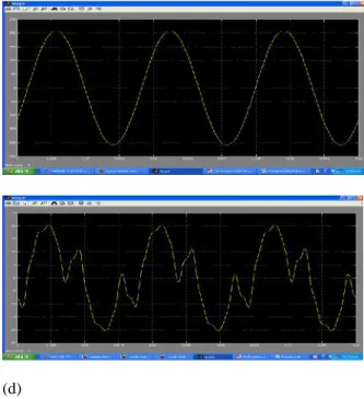
(d)
Fig. 18. (a) Current through distribution line, (b) Current flowing from node 11 to primary side of distribution transformer 11, (c) Current flowing through hot wire 1 of distribution transformer 11, and (d) DG harmonic current at 11thnode.
Vii. Conclusion
provided better damping for high-order harmonics if the equal equivalent rating of the DG was maintained. In the system without PFC capacitors, this crossover frequency was quite high, and end-ofline compensation performed better. However, the presence of capacitor in the system could significantly reduce this crossover frequency to around the 7th order harmonic, so the decision about which compensation strategy to use must be made
according to the system load
characteristics.Moreover, the effects of capacitor sizes, line impedance, and length on the crossover frequency were also analyzed in this paper. With the information about a distribution system, the crossover frequency between the two compensation strategies can be determined by using the model developed in this work, and proper priority can be assigned to the PV inverters at different locations. In our future work, we will consider a supervisory control system of the DGs with communication in order to control the participation from each PV inverter automatically according to the identified priority. Also, to provide an accurate effectiveness analysis of the harmonics compensation by using PV inverters throughout the day/season/year, the use of a statistical home model of a residential system and solar irradiance historic data could also be considered.Munir, Shirajum, and Yun Wei Li. "Residential distribution system harmonic compensation using PV interfacing inverter." Smart Grid, IEEE Transactions on4.2 (2013): 816-827.
References:
[1] J. Arrillaga and N. R. Watson, Power System Harmonics, 2nd ed.Hoboken, NJ, USA: Wiley, 2003, pp. 176–180.
[2] K. Wada, H. Fujita, and H. Akagi, Considerations of a shunt activefilter based on voltage detection for installation on a long distributionfeeder,” IEEE Trans. Ind. Appl., vol. 38, no. 4, pp. 1123–1130, July/Aug 2002.
[3] European Photovoltaic Industry Association (EPIA) “Annual report2011”, Mar. 2012, pp. 5–7. [4] Global Wind Energy Council (GWEC) “Global wind report, annualmarket update 2011”, Mar. 2012, pp. 4–7.
[5] M. Triggianese, F. Liccardo, and P. Marino,“Ancillary services performedby distributed generation in grid integration,” in Proc. IEEE
Int. Conf. Clean Electr. Power, 2007, pp. 164–170. [6] M. I. Marei, T. K. Abdel-Galil, E. F. El-Saadany, and M. M. A.Salama, “Hilbert transform based control algorithm of the DG interfacefor voltage flicker mitigation,” IEEE Trans. Power Del.,vol.20, pp. 1129–1133, Apr. 2005.
[7].Prodanovic,K.D.Brabandere,J.V.D.Keybus,T.Gre en,andJDriesen, “Harmonic and reactive power compensation as ancillary servicesin inverter-based distributed generation,” in IEE Proc. Gener.
Transm.Distrib., May 2007, vol. 1, pp. 432–438. [8] Y. W. Li, D. M. Vilathgamuwa, and P. C. Loh, “Microgrid powerquality enhancement using a three-phase four- wire grid-interfacingcompensator,” IEEE Trans. Ind. Appl., vol. 41, pp. 1707–1719, Nov. –Dec. 2005.
[9]C.H.Lin,W.L.Hsieh,C.S.Chen,C.T.Hsu,andT.T.Ku ,“Optimizationof photovoltaic penetration in distribution systems consideringannual duration curve of solar irradiation,” IEEE Trans. PowerSyst., vol. 27, no. 2, pp. 1090–1097, May 2012.
[10] A. Capasso, W. Grattieri, R. Lamedica, and A. Prudenzi, “A bottom-upapproach to residential load modeling,” IEEE Trans. Power Syst., vol.