Abstract—Dye-Sensitized Solar Cell (DSSC) is one of the equipment to convert sunlight into electricity. DSSC consists of anode electrode, titanium oxide ( ) thin film, sensitizer dye, electrolyte and cathode electrode (CE). In general, platinum (Pt) is usually used for CE. This paper studied the fabrication of CE using carbon nanotube (CNT) and CNT mixed with Poly (diallyl dimethylammonium chloride) (PDDA) (CNT/PDDA) as the substitution for Pt electrode. For the fabrication process, Electrophoresis Deposition (EPD) method was employed. CNT electrode was dried at room temperature at 25 oC or annealed at 400 oC for 1 hour, and CNT/PDDA CE was dried at room temperature at 25 oC. The thickness of CE we fabricated was around 15 . We adapted MK2 dye which was an organic dye for DSSC. Experimental results showed that the conversion efficiency of the DSSC in the case of CNT/PDDA CE (4.12%) was higher than that of the case of dried CNT electrode (2.78%) and annealed CNT electrode (3.49%) under the 1 sun illumination (100 ⁄ ). From this experiment results, PDDA has improved CE ability. In addition, CNT/PDDA CE do not need annealing process, so enabling flexible DSSC.
Index Terms—Dye sensitized-solar cell, carbon nanotube,
poly (diallyl dimethylammonium chloride), organic dye mk2, no annealing, flexible.
I. INTRODUCTION
Your goal is to simulate the usual appearance of papers in the. We are requesting that you follow these guidelines as closely as possible. Dye Sensitized-Solar Cell (DSSC) is a device that converts sunlight into electricity. This solar cell was firstly developed by Gratzel in 1991 who is a professor of the University of Swiss Federal Institution of Technology in Lausanne (EPFL). [1] In 2013, his team announced the highest conversion efficiency of 15 %. [2] The general structure composes of an anode electrode (dye-sensitized
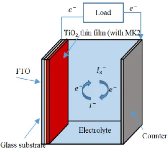
electrode on conductive glass), electrolyte-containing redox, and a catalyst counter electrode (CE). DSSC has attracted attention due to low production cost, simple structure and possibility for high conversion efficiency. [3], [4] Under the illumination of solar light, sensitizer dye absorbs visible light, then dye molecules are excited then electrons are produced. The electrons pass thought anode electrode, external circuit and CE. The function of CE is to transfer electrons from the external circuit back to the redox electrolyte [5], [6]. Oxidation-reduction reaction (ORR) is repeated between CE and electrolyte solution. ORR also happens between electrolyte and sensitizer dye. Sensitizer dye is deoxidized and gets back to the original state. DSSC
Manuscript received September 13, 2018; revised November 21, 2018.. The authors are with Ritsumeikan University, Science and Engineering, Kusatsu, Japan (e-mail: [email protected]).
repeats these processes and creates electrical current (Fig. 1). Usually, platinum (Pt) is used for CE of DSSC because it catalyzes ORR with high efficiency than other metals and has superior electro catalytic activity [7], [8]. Nevertheless, Pt electrode has some drawbacks such as high costs, short-time durability and rare metal [9], [10]. Therefore, we should find substitution for Pt-based CE. One promising substitution is Carbon nanotube (CNT), which has advantages of large surface area, high electrical conductivity, low cost and chemical stability [9], [11]-[13]. However, using CNT for CE causes low conversion efficiency and early degradation compared with Pt.
Fig. 1. DSSC configuration.
In this paper, we proposed a high catalysis CE for DSSC as a substitution for Pt. There are some methods to laminate carbon materials including Electrophoresis Deposition method (EPD), spin coating [9] or doctor-blading [14], [15]. EPD method is coating method by charging particles and has some advantages (short fabrication time, controllable thin film thickness and simple setting). It has been proved that Poly (diallyl dimethylammonium chloride) (PDDA) has ability of withdrawing electrons from CNT. [16] By using this method, we fabricated and tested CNT electrode and CNT mixed with PDDA (CNT/PDDA) electrode.
II. EXPERIMENT METHOD A. Preparing Thin Film
As thin film fabricated by EPD method, we used 0.2g of P25 powder (JAPAN AEROSIL), 40mL of ethanol (Wako) and 0.2g of Polyethylene glycol (PEG, Wako, average molecular 1500) to make solution for EPD. They were mixed at the speed of 700rpm for 24 hours
The Impact of PDDA in CNT Counter Electrode on the
Conversion Efficiency of DSSC
with magnetic stirrer. The anode (Aluminum plate, 20×20× 1mm) and counter electrode (FTO (fluorine doped
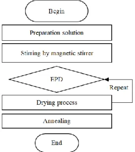
coated glass substrate 20×20×1.8 mm) were placed in parallel into the solution, leaving 10 mm between anode and counter electrode with a silicon strip, and EPD current was set at 0.12 mA from a current source (ADVANTEST R6144). In process of EPD to fabricate four layers thin film, we executed 25 seconds EPD four times and drying process three times at 60oC for 1 minute each time in a dry oven (Iuchi, DO-450). Fig. 2 shows the flow for fabrication of multilayer thin film. After completing deposition, thin film was annealed at 400oC for 1 hour with an electric furnace (ASONE SMF-1).
Fig. 2. Fabricating multilayer flow.
B. Carbon Nanotube CE
By using EPD method, we fabricated three types of CE. Firstly, we prepared pure CNT electrode. To execute EPD process, we used CNT dispersion liquid (KJ, X7006L, MWCNT). For the EPD to prepare CNT electrode, the anode (FTO substrate 40×20×1.8mm) and counter electrode (Aluminum plate 40×20×1mm) were placed parallel in CNT dispersion, with 9 mm between anode and counter with silicon strip. The EPD voltage was set at 3V from a direct current stabilized power source equipment (AD-8723D, AND) and EPD time was set to be 80 seconds. After deposition, fabricated electrode was annealed at 400 oC for 1 hour or dried at room temperature of 25 oC for 24 hours. Thickness of the fabricated CNT electrodes was measured.
C. Preparing PDDA on CNT CE
Secondly, PDDA solution was dropped on CNT electrode. We dropped two types with different PDDA concentration (20wt % or 1wt %) on dried CNT electrode or immediately after EPD process (Fig. 3). After dropping, they were dried at room temperature of 25 oC for 24 hours.
D. Preparing CNT Mixed with PDDA CE
Finally, we made CNT and PDDA mixed solution (CNT/PDDA) to conduct EPD. To make CNT/PDDA solution, we used CNT dispersion solution (KJ, X7006L),
water (Monotaro). We mixed 20wt % of PDDA solution with suitable amount of deionized water to obtain 1wt % PDDA solution. After that, CNT and 1wt % PDDA solution were mixed in proportion of 10:1. Then we obtained CNT/PDDA solution. To execute EPD process, voltage was set 3V and EPD time was 90 seconds. After the EPD process, CNT/PDDA CE was dried at room temperature of 25 oC for 24 hours.
Fig. 3. Demonstration of dropping PDDA solution on CNT electrode.
E. Electrolyte Blending and Soaking Sensitizer Dye
The electrolyte was consisted of 0.6 M of 1.2-dimethyl-3-propylimidazolium iodide (Wako), 0.1M of Lil (sigma Aldrich), 0.2 M of (sigma Aldrich), 0.5 M of 4-tert-butylpyridine (sigma Aldrich) and 10mL of acetonitrile (Wako).
The prepared thin film was soaked in sensitizer dye solution at 25 oC for 3 hours. The sensitizer dye solution was consisted of 10mg of organic dye
(2-Cyano-3-[5’’’-(9-
ethyl-9H-carbazol-3-yl)-3’,3’’,3’’’,4-tetra-n-hexyl-[2,2’,5’,2”,5”,2”’]-quarterthiophen-5-yl] acrylic acid)
(MK2, sigma Aldrich) and 108mL of toluene (Wako). In general, as a sensitizer dye, ruthenium is usually used. Ruthenium dye absorbed long wavelength light, so it realizes high conversion efficiency. However, high cost material and environmental hazards are problems of ruthenium dye. So, in order to improve these problems, researchers try to find natural dye for DSSC. Therefore, we used organic dye (MK2 dye).After the thin film absorbed
the dye, its surface was rinsed by toluene and deionized water continuously to remove any dye that had not adsorbed on the surface of thin film. Then thin film was dried at 80 o
C in dry oven for 5 mins.
F. Making DSSC and Measurements
We assembled DSSC using two electrodes (dye soaked
thin film and fabricated CE) and electrolyte as shown in Fig. 4. Masking tape was cut 25 square and it was stuck on thin film with MK2 dye. We dropped electrolyte on this active area and sealed by CE.
The thickness of thin film and CE were measured by a step gauge (BRUKER DektakXT), and surface of
thin film was observed by a metallurgical microscope (OLYMPUS BX60M). Absorption spectrum of dye adsorbed thin film was measured by a spectrophotometer (SHIMADZU, UV-3600). The
open-PDDA
FTO
( ⁄ ), fill factor FF (%) and conversion efficiency (%) of DSSC was measured with solar simulator (OAI, TriSOL) by simulating the Sunlight (AM1.5, 100mW/cm2).
Fig. 4. Assembling DSSC.
III. RESULT AND DISCUSSION A. Evalution of Thin Film by Metallurgical Microscope
Fig. 5 shows the surface image of thin film. Thin film with single layer has many crevices (Fig. 5 (a)) in contrast, thin film with four layers (Fig. 5 (b)) has no cracks. The occasion of cracks is due to the volatilization of ethanol. [17] In order to reduce crevices on the thin film, EPD process was executed four times and drying process was executed three times at high temperature. Cracks on the surface of film reduce the amount of sensitized dye adsorbed and cause low conversion efficiency.
Fig. 5. Surface of thin film (a) single layer, (b) four layers.
B. Absorption Spectra
Fig. 6 shows absorption spectra of absorbed dye in
thin film. To compare, two types thin film were measured (single layer and four layers). thin film with four layers adsorbed much dye than the case of single layer. The maximum adsorption wavelength of MK2 dye is 480 nm. From Fig. 6, absorption of the visible range of about 400-600 nm was better with four layers. From surface image of
thin film and absorption spectra, multilayer thin film has essential role in DSSC anode electrode.
Fig. 6. Absorption spectra of absorbed dye in TiO2 thin film.
C. Solar Cell Measurement 1) Pure CNT CE
Table I shows measurement results when we used two patterns (dried and annealed) pure CNT CE. It shows that, short-circuit current density of dried CNT and annealed CNT have different values, which were 10.31 and 12.70
⁄ respectively. The conversion efficiency of these two patterns were 2.78% and 3.49% respectively. Compared with dried CNT, annealed CNT achieved better performance. Annealing process for CE is important because it removed dispersion solution and stuck CNT with FTO substrate. To further improve the efficiency, we tried to fabricate CNT CE using PDDA solution.
TABLEI:MEASUREMENT DATA OF THE DSSCUSING DRIED CNT AND
ANNEALED CNT
Sample Jsc(mA/cm2) Voc (V) FF (%) Eff (%)
Dried CNT 10.31 0.67 40.62 2.78
Annealed CNT 12.70 0.65 41.95 3.49
2) CNT CE dropped PDDA solution
Table II shows measurement results when we used CNT CE dropped PDDA solution after EPD process. We measured three patterns of counter electrode (dropped 20wt%, 1wt% PDDA, and dropped PDDA after EPD), but these conditions had almost same results. All parameters were lower compared with annealed CNT electrode. This is because CNT cannot contact electrolyte because of the presence of PDDA layer on the CNT, as shown in Fig. 7, Fig.8 (a) shows the picture of a CNT CE with PDDA solution dropped on its surface, compared with a pure CNT electrode in Fig. 8 (b).
TABLEII:RESULT OF THE DSSCMEASUREMENT WITH DROOPING PDDA
ON CESURFACE
Fig. 7. Image of CNT CE dropped PDDA solution. Sample Jsc(mA/cm2) Voc
(V) FF (%)
Eff (%) Dropping PDDA
(20wt%) 6.21 0.22 27.21 0.38
Dropping PDDA (1wt%) 4.24 0.24 30.82 0.32
Dropping PDDA after
EPD 5.14 0.28 25.74 0.38 Sunlight from solar simulator
Electrolyt e
CE (CNT mixed with PDDA)
Anode electrode ( thin film with
dye) Spacer
(a )
(b )
0 10 20 30 40 50 60 70 80
300 400 500 600 700 800
ab
s(%
)
Wavelenght (nm)
four layers
single layer
0 10 20 30 40 50 60 70 80
300 400 500 600 700 800
ab
s(%
)
Wavelenght (nm)
four layers
Fig. 8. Picture of CNT CE with (a) dropped PDDA solution, and (b) pure CNT electrode.
3) CNT/PDDA solution
TABLEIII: RESULT OF DSSCMEASUREMENT WITH DRIED OR ANNEALED
CNT AND CNT/PDDAELECTRODE
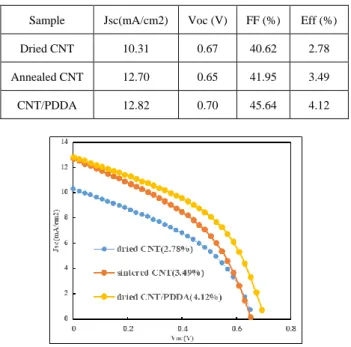
Fig. 9. - curve dried CNT CE (blue), annealed CNT CE (orange), dried CNT/PDDA CE (yellow).
Table III shows results when we used pure CNT electrode (dried or annealed) and CNT electrode mixed with PDDA solution. In case of this proportion CNT: PDDA (1wt %)=10:1, the best energy conversion efficiency was achieved (4.12%). Therefore, it is obvious that PDDA helped improve the efficiency significantly.
Fig. 9 shows the photocurrent density-voltage curve for DSSC based on different CEs (dried CNT, sintered CNT and dried CNT/PDDA) measured under the illumination of 1 sun. of sintered CE and dried CNT/PDDA CE increased remarkably compared with dried CNT CE. Compared with dried CNT CE and dried CNT/PDDA CE, FF value of dried CNT/PDDA CE was improved.
IV. CONCLUSION
In this paper, we fabricated CNT CE and CNT/PDDA CE using EPD method for DSSC. A little PDDA solution improved quality of CE. Experiment result shows that the conversion efficiency could be improved up to about 50 % (2.78% to 4.12%) by PDDA solution. Besides, our proposed method does not need annealing process, therefore
ACKNOWLEDGEMENT
The authors wish to thank to Minemoto laboratory of Ritsumeikan University. We got to use Solar simulator (OAI, TriSOL), step gauge (BRUKER DektakXT) and spectrophotometer (SHIMADZU, UV-3600) for DSSC performance from Minemoto laboratory
REFERENCES
[1] B. O’Regan and M. Gretzel, ―A low-cost, high-efficiency solar cell based on dye-sensitized colloidal films,‖ Nature, vol. 353, pp. 737-740, October 24, 1991.
[2] J. Burschka, N. Pellet, S. J. Moon, R. Humphry-Baker, P. Gao, M. K. Nazeeruddin, and M. Gratzel, ―Sequential deposition as a route to high-performance perovskite-sensitized solar cells,‖ Nature, vol. 499, pp. 316-319, July 18, 2013.
[3] G. H. Guai, Q. L. Song, Z. S. Lu, C. M. Ng, and C. M. Li, ―Tailor and functionalize compact layer by acid treatment for high performance dye-sensitized solar cell and its enhancement mechanism,‖ Renewable Energy, vol. 51, pp. 29-35, 2013.
[4] S. A. Mozaffari, M. Ranjbar, E. Kouhestanian, H. S. Amoli, and M. H. Armanmehr, ―An investigation on the effect of electrodeposited nanostructured ZnO on the electron transfer process efficiency of TiO2 based DSSC,‖ Materials Science in Semiconductor Processing,
vol. 40, pp. 285-292, 2015.
[5] H. Yua, S. Zhanga, H. Zhaoa, G. Willb, and P. Liua, ―An efficient and low-cost TiO2 compact layer for performance improvement of dye-sensitized solar cells,‖ Electrochimica Acta., vol.54, pp. 1319-1324, 2009.
[6] M. Hamadanian, V. Jabbari, A. Gravand, and M. Asad, ―Band gap engineering of TiO2 nanostructure-based dye solar cells (DSCs)
fabricated via electrophoresis,‖ Surface & Coatings Technology, vol. 206, no. 22, pp. 4531-4538, 2012.
[7] R. Bajpai, S. Roy, P. Kumar, P. Bajpai, N. Kulshrestha, J. Rafiee, N. Koratkar, and D. S. Misra, ―Graphene supported platinum nanoparticle counter-electrode for enhanced performance of dye-sensitized solar cells,‖ Acs Appl. Mater. & Interfaces, vol. 3, no. 10, pp. 3884-3889, 2011.
[8] C. H. Yoon, R. Vittal, J. Lee, W. S. Chae, and K. J. Kima, ―Enhanced performance of a dye-sensitized solar cell with an electrodeposited-platinum counter electrode,‖ Electrochimica Acta., vol. 53, pp. 2890-2896, 2008.
[9] X. Mao, S. Zhang, Q. Ma, L. Wan, H. Niu, S. Qin, S. Miao, and J. Xu, ―Non-covalent construction of non-Pt counter electrodes for high performance dye-sensitized solar cells,‖ J. Sol-Gel Sci. Technol., vol. 74, pp. 240-248, 2015.
[10] J. Chen, K. Li, Y. Luo, X. Guo, D. Li, M. Deng, S. Huang, and Q. Meng, ―A flexible carbon counter electrode for dye-sensitized solar cells,‖ CARBON, vol. 47, no. 11 , pp. 2704-2708, 2009.
[11] W. J. Lee, E. Ramasamy, D. Y. Lee, and J. S. Song, ―Efficient dye-sensitized solar cells with catalytic multiwall carbon nanotube counter electrodes,‖ Acs Applied Materials & Interfaces, vol. 1, no. 6, pp. 1145-1149, 2009.
[12] Z. Huang, X. Liu, K. Li, D. Li, Y. Luo, H. Li, W. song, L. Chen, and Q. Meng, ―Application of carbon materials as counter electrodes of dye-sensitized solar cells,‖ Electrochemistry Communication, vol. 9, pp. 596-598, 2007.
[13] H. Choi, H. Kim, S. Hwang, W. Choi, and M. Jeon, ―Dye-sensitized solar cells using graphene-based carbon nano composite as counter electrode,‖ Solar Energy Materials & Solar Cells, vol. 95, pp. 323-325, 2011.
[14] J. Chen, K. Li, Y. Luo, X. Guo, D. Li, M. Deng, S. Huang, and Q. Meng, ―A flexible carbon counter electrode for dye-sensitized solar cells,‖ CARBON, vol. 47, no. 11, pp. 2704-2708, 2009.
[15] X. Fang, M. Li, K. Guo, Y. Zhu, Z. Hu, X. Liu, B. Chen, and X. Zhao, ―Improved properties of dye-sensitized solar cells by incorporation of graphene into the photoelectrodes,‖ Electrochimica Acta., vol. 65, pp. 174-178, 2012.
[16] S. Wang, D. Yu, and L. Dai, ―Polyelectrolyte functionalized carbon nanotubes as efficient metal-free electrocatalysts for oxygen reduction,‖ Journal of the American Chemical Society, vol. 133, no. 14, pp. 5182-5185, 2011.
[17] H. Chang, H. T. Su, W. A. Chen, K. D. Huang, S. H. Chien, S. L. Chen, and C. C. Chen, ―Fabrication of multilayer TiO2 thin films for
dye-sensitized solar cells with high conversion efficiency by electrophoresis deposition,‖ Solae Energy, vol. 84, pp. 130-136, 2010. Sample Jsc(mA/cm2) Voc (V) FF (%) Eff (%)
Dried CNT 10.31 0.67 40.62 2.78
Annealed CNT 12.70 0.65 41.95 3.49
CNT/PDDA 12.82 0.70 45.64 4.12 (b
Yoshiki Kurokawa was born in Shiga, Japan on April 26, 1994. He received bachelor’s degree in Department of Science and Engineering from Ritsumeikan University, Shiga, Japan in March 2017 and was admitted to a postgraduate course at same University on April 2017. He also belongs to an electronics system course of Department of Science and Engineering. He is now in the first year. He is making a study of DSSC by using electrophoresis deposition in the graduate course.
D. Trang Nguyen was born in Vietnam in 1986. He received the BS degree in 2009 from the Department of Telecommunication Systems Hanoi University of Science and Technology, Hanoi, Vietnam. After that he received the ME in 2011 from the Department of Electronics and Electrical Engineering, Dongguk University, Seoul, South Korea. From 2011 to 2014, he completed his Ph.D program in integrated science and engineering at the Ritsumeikan University, Kyoto, Japan. After earning his Ph.D, he was a quality assurance engineer at Takako Industries, Inc. from 2015 to 2017. Currently, he is a postdoctoral researcher at the Ritsumeikan Global Innovation Research Organization, Ritsumeikan University. His fields of interest include Biofuel Cells, Solar Cells, Biosensors and Hydrogen Energy.