For use with HOBO H21, H22, U30, UX90, and UX120 series data loggers, and HOBO data nodes
© 2005–2012 Onset Computer Corporation. All rights reserved. Onset, HOBO, and HOBOware are registered trademarks of Onset
Applies to these WattNode Pulse Output kWh Transducers:
Onset Part No. Configuration / VAC Output Maximum Pulse Output WattNode Part No.
T-WNB-3Y-208 Single-phase 120 or
Wye 208-240
Pulses representing kWh 4 Hz WNB-3Y-208-P
T-WNB-3Y-208-P Single-phase 120 or
Wye 208-240
Pulses representing kWh 4 Hz WNB-3Y-208-P
option P3
T-WNB-3D-240 Delta 208-240 Pulses representing kWh 4 Hz WNB-3D-240-P
T-WNB-3D-480 Delta (or Wye) 480 Pulses representing kWh 4 Hz WNB-3D-480-P
DANGER!
—HIGH VOLTAGE HAZARDInstalling transducers in an energized electrical enclosure or on any energized conductor can result in severe injury or death. These transducers are for installation by qualified personnel only. To avoid electrical shock, do not perform any installation or servicing of these transducers unless you are qualified to do so. Disconnect and lock-out all power sources during installation and servicing. Please read transducer user manuals for instructions and use.
This document provides instructions on connecting the WattNode Pulse Output kWh Transducers listed above to HOBO H21, H22, U30, UX90, and UX120 series data loggers and to ZW series data nodes. Note: For information on connecting the kWh transducer to the power source and other transducer details, refer to the WattNode documentation provided by Continental Control Systems.
Required
• Selected WattNode Pulse Output kWh Transducer
• Appropriately rated Current Transducer(s)
• Smart Sensor-compatible HOBO data logger (H21, H22, or U30 series) with:
o Pulse Input Adapter(s), Onset Part No: S-UCC-M00x*
o HOBOware® Pro Software, version 2.2 or higher (2.4 or higher for U30)
• 22 AWG twisted pair wire (customer supplied) for UX120 series with HOBO Pro Software, version 3.2.0 or higher
• Pulse input-compatible HOBO data node (ZW series) and HOBO data logger (UX90 series) with:
o Onset Part No: CABLE-2.5-STEREO*
o HOBOware Pro Software, version 3.0 or higher for ZW series and version 3.3 or higher for UX90 series
* For monitoring power demand as well as generated power, a second S-UCC-M00x pulse input adapter (for H21, H22, or U30 series) or CABLE-2.5-STEREO (for pulse input-compatible ZW series) is required (at output terminal P2).
WattNode Pulse Output kWh Transducer Features
• The WattNode transducer includes three LEDs—one per phase—for diagnostics and indication of power direction, low power factor, and correctly installed CTs.
• The WattNode transducer provides bidirectional power measurements (positive and negative power). It can be used for conventional power and energy measurement as well as for net metering and PV applications. For monitoring power demand as well as generated power, a second S-UCC-M00x pulse input adapter (for H21, H22, or U30 series) or CABLE-2.5-STEREO (for pulse input-compatible ZW series) is required (at output terminal P2).
WattNode Pulse Output kWh Transducer (Onset Part No. T-WNB-3Y-208-P shown)
• The T-WNB-3Y-208-P can measure two or three separate branch circuits simultaneously. Note that an S-UCC-M00x pulse input adapter (for H21, H22, or U30 series) or a CABLE-2.5-STEREO (for pulse input-compatible ZW series) is required for each circuit monitored.
Note: Refer to the WattNode WNB Series Installation and Operation Manual for details of these features.
Configuring the System
To configure the system, refer to the applicable connection diagram that corresponds to your electrical power configuration. Also refer to the WattNode manual for additional configurations.
White Black S-UCC-M00x
Pulse Input Adapter
Ou tp ut P3 P2 P1 COM White Black Connect to
Smart Sensor port
Connect to pulse port HOBO H21, H22, or U30 Series Data Logger
(H22-001 shown)
CABLE-2.5-STEREO
HOBO ZW Series Wireless Data Node
Ou tp ut P3 P2 P1 COM
HOBO UX120 Series Data Logger
Connect ground ( ) terminal from UX120 terminal block to COM
Connect (+) terminal from UX120 terminal block to P1
Ou tp ut P3 P2 P1 COM Customer-supplied 22 AWG twisted pair
HOBO UX90-001/M Data Logger
Ou tp ut P3 P2 P1 COM White Black Red wire not used CABLE-2.5-STEREO Red wire not used
Figure 1: Connecting HOBO Data Logger or Data Node to WattNode Electrical Service Types
Below is a list of service types, with connections and recommended WattNode models. Note: the WattNode ground connection improves measurement accuracy, but is not required for safety.
Model Type Phase to Neutral Phase to Phase Service Types* Electrical
WNB-3Y-208-P Wye 120 VAC 208–240 VAC
1 Phase 2 Wire 120V with neutral 1 Phase 3 Wire 120V/240V with neutral 3 Phase 4 Wire Wye 120V/208V with neutral
WNB-3D-240-P or Wye Delta 120–140 VAC 208–240 VAC
1 Phase 2 Wire 208V (No neutral) 1 Phase 2 Wire 240V (No neutral) 1 Phase 3 Wire 120V/240V with neutral 3 Phase 3 Wire Delta 208V (No neutral) 3 Phase 4 Wire Wye 120V/208V with neutral 3 Phase 4 Wire Delta 120/208/240V with neutral
WNB-3D-480-P or Wye Delta 277 VAC 480 VAC
3 Phase 3 Wire Delta 480V (No neutral) 3 Phase 4 Wire Wye 277V/480V with neutral 3 Phase 4 Wire Delta 240/415/480V with neutral *The wire count does NOT include ground. It only includes neutral (if present) and phase wires.
Single-Phase Two-Wire with Neutral
This configuration is most often seen in homes and offices. The two wires are neutral and line. For these models, the WattNode is powered from the N and ØA terminals.
Figure 2: Single-Phase Two-Wire Connection
Recommended WattNode Model
The following table shows the WattNode model that should be used, depending on the line to neutral voltage. Line to Neutral Voltage WattNode Model
120 VAC WNB-3Y-208-P
Single-Phase Three-Wire
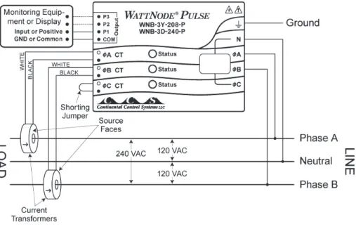
This configuration is seen in North American residential and commercial service with 240 VAC for large appliances. The three wires are neutral and two line voltage wires with AC waveforms 180° out of phase; this results in 120 VAC between either line wire (phase) and neutral, and 240 VAC (or sometimes 208 VAC) between the two line wires (phases).
Figure 3: Single-Phase Three-Wire Connection
Recommended WattNode Models
measurements. If phase B may not be present, you should use the WNB-3Y-208-P (see Single-Phase Two-Wire with Neutral
above).
WattNode Power Source WattNode Model
N and ØA (Neutral and Phase A) WNB-3Y-208-P
ØA and ØB (Phase A and Phase B) WNB-3D-240-P
Single-Phase Two-Wire without Neutral
This is seen in residential and commercial service with 208 to 240 VAC for large appliances. The two wires are two line voltage wires with AC waveforms 120° or 180° out of phase. Neutral is not used. This results in 240 VAC (or 208 VAC) between the two line wires (phases). For this configuration, the WattNode is powered from the ØA and ØB (phase A and phase B) terminals.
For best accuracy, we recommend connecting the WattNode N (neutral) terminal to earth ground. This will not cause ground current to flow because the neutral terminal is not used to power the WattNode.
Figure 4: Single-Phase Two-Wire without Neutral Connection
Recommended WattNode Model
This configuration is normally measured with one WattNode model.
Phase-to-Phase Voltage WattNode Model
208 - 240 VAC WNB-3D-240-P
However, if neutral is available, then you may also use the WNB-3Y-208-P model. If you use the WNB-3Y-208-P, you will need to hook up the WattNode as shown in section Single-Phase Three Wire and connect neutral. You will need two CTs. Grounded Leg
In rare cases (non-residential), one of the lines (phase A or phase B) may be grounded. You can check for this by using a multimeter (DMM) to measure the voltage between each phase and ground. If you see a reading between 0 and 5 VAC, that leg (phase) is probably grounded.
The WattNode will correctly measure circuits with a grounded leg, but the measured voltage and power for the phase will be zero and the status LED will not light for whichever phase is grounded, because the voltage is near zero. If you have a grounded leg configuration, you can save money by removing the CT for the grounded phase, since all the power will be measured on the non-grounded phase. We recommend putting the grounded leg (phase) on the ØB input and attaching a note to the WattNode indicating this configuration for future reference.
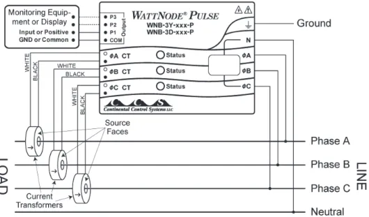
Three-Phase Four-Wire Wye
This is typically seen in commercial and industrial environments. The wires are neutral and three power lines with AC waveforms shifted 120° between the successive phases. With this configuration, the line voltage wires may be connected to the ØA, ØB,and ØC terminals in any order, so long as the CTs are connected to matching phases. It is important that you connect N (neutral). For these models, the WattNode is powered from the N and ØA terminals.
Figure 5: Three-Phase Four-Wire Wye Connection
Recommended WattNode Models
The following table shows the WattNode model that should be used, depending on the line to neutral voltage and line to line voltage (also called phase to phase voltage).
Line to Neutral Voltage Line to Line Voltage WattNode Model
120 VAC 208 VAC WNB-3Y-208-P
Note: you may also use the following delta WattNode models to measure three-phase four-wire wye circuits. The only difference is that delta WattNode models are powered from ØA and ØB, rather than N and ØA. If neutral is present, it must be connected for accurate measurements.
Line to Neutral Voltage Line to Line Voltage WattNode Model
120 - 140 VAC 208 - 240 VAC WNB-3D-240-P
277 VAC 480 VAC WNB-3D-480-P
Three-Phase Three-Wire Delta (No Neutral)
This is typically seen in manufacturing and industrial environments. There is no neutral wire, just three power lines with AC waveforms shifted 120° between the successive phases. With this configuration, the line voltage wires may be connected to the ØA, ØB,and ØC terminals in any order, so long as the CTs are connected to matching phases. For these models, the WattNode is powered from the ØA and ØB (phase A and phase B) terminals. Note: all delta WattNode models provide a neutral connection N, which allows delta WattNode models to measure both wye and delta configurations.
For best accuracy, we recommend connecting the N (neutral) terminal to earth ground. This is not necessary on balanced three-phase circuits, where the ground-to-phase A, ground-to-phase B, and ground-to-phase C voltages are all roughly the same. This will not cause ground current to flow because the neutral terminal is not used to power the WattNode.
Figure 6: Three-Phase Three-Wire Delta (No Neutral) Connection
Recommended WattNode Models
The following table shows the WattNode model that should be used, depending on the line to neutral voltage and line to line voltage (also called phase to phase voltage).
Line to Line Voltage WattNode Model
208 - 240 VAC WNB-3D-240-P
480 VAC WNB-3D-480-P
Grounded Leg
In rare cases, one of the phases may be grounded. You can check for this by using a multimeter (DMM) to measure the voltage between each phase and ground. If you see a reading between 0 and 5 VAC, that leg is probably grounded.
The WattNode will correctly measure circuits with a grounded leg, but the measured voltage and power for the phase will be zero and the status LED will not light for whichever phase is grounded, because the voltage is near zero. Also, one or both of the active (non-grounded) phases may show yellow or red/yellow LED flashing because the grounded leg configuration results in unusual power factors.
For optimum accuracy with a grounded leg, you should also connect the N (neutral) terminal on the WattNode to the ground terminal; this will not cause any ground current to flow because the neutral terminal is not used to power the WattNode. If you have a grounded leg configuration, you can save money by removing the CT for the grounded phase, since all the power will be measured on the non-grounded phases. We recommend putting the grounded leg on the ØC (Phase C) input and attaching a note to the WattNode indicating this configuration for future reference.
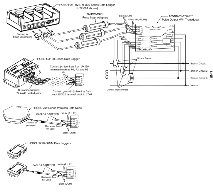
Separate Branch Circuits Connection (T-WNB-3Y-208-P** only)
White (P1, P2, P3)
S-UCC-M00x Pulse Input Adapters
Ou tp ut P3 P2 P1 COM A CT B CT C CT Status Status Status N A B C Black (COM) LOAD
Branch Circuit 1
Neutral LI N E Source Faces White Black White Black White Black Current Transformers
Branch Circuit 2
Branch Circuit 3
Ou tp u t P3 P2 P1 COM CABLE-2.5-STEREO Red wires not used
White (P1, P2)
Black (COM)
T-WNB-3Y-208-P** Pulse Output kWh Transducer
Connect to Smart Sensor ports
R
WNB-3Y-208-P
Connect ground ( ) terminal from each UX120 terminal block to COM Connect (+) terminals from UX120
terminal blocks to P1, P2, and P3
Ou tp u t P3 P2 P1 COM Connect to pulse port Customer-supplied 22 AWG twisted pairs
HOBO H21, H22, or U30 Series Data Logger (H22-001 shown)
HOBO UX120 Series Data Logger
HOBO ZW Series Wireless Data Node
Ou tp u t P3 P2 P1 COM CABLE-2.5-STEREO Red wires not used
White (P1, P2)
Black (COM)
HOBO UX90-001/M Data Loggers
Figure 7: Separate Branch Circuits Connection
** The T-WNB-3Y-208-P can measure two or three separate branch circuits simultaneously. Note that a S-UCC-M00x pulse input adapter (if used with H21, H22, or U30 data loggers) or a CABLE-2.5-STEREO (if used with ZW data node or UX90 logger pulse ports) is required for each circuit monitored. A three-branch circuit arrangement is shown for H21, H22, U30, and UX120 data loggers.