Quick Start Guide
007-5621-001COPYRIGHT
© 2010 SGI. All rights reserved; provided portions may be copyright in third parties, as indicated elsewhere herein. No permission is granted to copy, distribute, or create derivative works from the contents of this electronic documentation in any manner, in whole or in part, without the prior written permission of SGI.
LIMITED RIGHTS LEGEND
The software described in this document is “commercial computer software” provided with restricted rights (except as to included open/free source) as specified in the FAR 52.227-19 and/or the DFAR 227.7202, or successive sections. Use beyond license provisions is a violation of worldwide intellectual property laws, treaties and conventions. This document is provided with limited rights as defined in 52.227-14.
The electronic (software) version of this document was developed at private expense; if acquired under an agreement with the USA government or any contractor thereto, it is acquired as “commercial computer software” subject to the provisions of its applicable license agreement, as specified in (a) 48 CFR 12.212 of the FAR; or, if acquired for Department of Defense units, (b) 48 CFR 227-7202 of the DoD FAR Supplement; or sections succeeding thereto. Contractor/manufacturer is SGI, 46600 Landing Parkway, Fremont, CA 94538.
TRADEMARKS AND ATTRIBUTIONS
Silicon Graphics, SGI, and the SGI logo are trademarks or registered trademarks of Silicon Graphics International Corp. or its subsidiaries in the United States and/or other countries worldwide.
Internet Explorer is a registered trademark of Microsoft Corporation in the United States and/or other countries. Java is a trademark of Sun Microsystems, Inc. Mozilla Firefox is a registered trademark of the Mozilla Foundation. All other trademarks mentioned herein are the property of their respective owners.
Contents
Hardware Overview . . . . 2
IS-NAS Server Front Controls and Indicators . . . . 2
IS-NAS Server Rear Panel . . . . 4
IS-NAS Server Rear Panel–LEDs and Buttons. . . . 5
RAID Controller/Drive Enclosure Rear Panel . . . . 7
Drive Expansion Enclosure Rear Panel . . . . 7
System Indicators . . . . 8
The RAID Controller Module . . . . 9
Drive Locations and Indicators . . . . 9
Powering On an IS-NAS Server. . . . 11
Software Configuration . . . . 12
Accessing the Web Manager SMU . . . . 12
Configuring SMU for Your Environment . . . . 15
General Setup and Network Settings . . . . 16
File System Configuration . . . . 20
Serving the File System . . . . 21
Documentation . . . . 22
After Software Configuration . . . . 22
This document guides a knowledgeable user through the basic setup of an SGI InfiniteStorage NAS 50/100 system. Unless otherwise negotiated, your network-attached storage (NAS) system comes racked and cabled. You only need to configure the NAS software management services. Professional assistance with the setup of your new NAS solution is available through SGI Managed Services. If you ordered such service, please contact the SGI Customer Support Center to schedule the on-site visit.
For more information on the hardware/software used with the SGI InfiniteStorage NAS 50/100, see “Documentation” on page 22.
This quick start guide as well as other SGI documents can be accessed and downloaded from the SGI publications library:
http://docs.sgi.com
Various formats are available. This library contains the most recent and most comprehensive set of online books, release notes, man pages, and other information related to SGI products. This document describes the following topics:
• “Hardware Overview” on page 2
• “Powering On an IS-NAS Server” on page 11 • “Software Configuration” on page 12
• “After Software Configuration” on page 22 • “Contacting SGI” on page 23
Hardware Overview
Your NAS system consists of the following hardware elements:
• A System Management Unit (SMU), either internal or external, depending on system configuration
• SGI InfiniteStorage NAS 50/100 server(s), referred to as IS-NAS server(s)
• Storage subsystem, which includes the storage array controllers and/or drive trays populated with disk drives
• Fibre Channel (FC) switch, depending on system configuration • Private management network
• Public data network
The IS-NAS server is a highly scalable and modular NAS server with multi-gigabit throughput from network to disk.
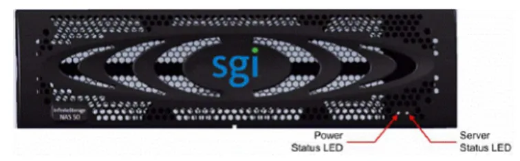
IS-NAS Server Front Controls and Indicators
Figure 1-1 shows the LEDs on the front of an IS-NAS server. Table 1-1 and Table 1-2 describe the various states of the LEDs.
Table 1-1 Power Status LED (Green)
State Meaning
Green Normal operation with a single IS-NAS server or an active cluster node in operation.
Slow Flash The system has been shut down. Flashes once every three seconds. Medium Flash The IS-NAS server is available to host file services but it not currently
doing so. Flashes once every .8 seconds.
Fast Flash The IS-NAS server is rebooting. Flashes five times per second. Off The IS-NAS server is not powered up.
Table 1-2 Server Status LED (Amber)
State Meaning
Amber Critical failure. The IS-NAS server is not operational.
Slow Flash System shutdown has failed. Flashes once every three seconds. Medium Flash The IS-NAS server needs attention; a non-critical failure has been
detected. For example, a fan or power supply has failed. Flashes once every .8 seconds.
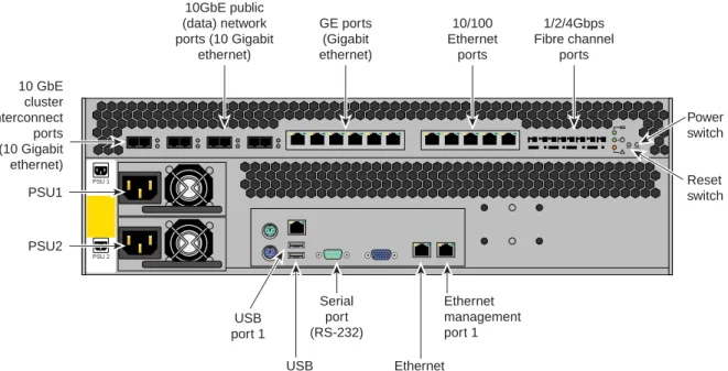
IS-NAS Server Rear Panel
Figure 1-2 shows the rear panel components of an IS-NAS server.
Figure 1-2 IS-NAS Rear Panel Components
+ -! RST PWR PSU 2 PSU 1 USB port 2 Serial port (RS-232) Ethernet management Ethernet management port 1 USB port 1 PSU2 PSU1 10 GbE cluster interconnect ports (10 Gigabit ethernet) 10GbE public (data) network ports (10 Gigabit
ethernet) GE ports (Gigabit ethernet) 10/100 Ethernet ports 1/2/4Gbps Fibre channel ports Power switch Reset switch
IS-NAS Server Rear Panel–LEDs and Buttons
As shown in Figure 1-3, the rear panel of an IS-NAS server contains three status LEDs that indicate server status and two buttons that are used to power up and reset the server.
Figure 1-3 Rear Panel LEDs and Buttons
The NVRAM, Power, and Server LEDs indicate if the server is powered on, its operation state, and if the NVRAM is currently being protected by battery backup power. Table 1-3, Table 1-4, and Table 1-5 describe the various states of the LEDs.
Table 1-3 NVRAM Status LED (Green/Amber)
State Meaning
Solid Green Normal operation.
Flashing Green NVRAM contents are protected by battery power. Solid Amber Battery pack is faulty or not fitted properly. Off Disabled or NVRAM battery power has exhausted.
NVRAM status LED Power status LED Server status LED
+ -! RST PWR Reset button Power button
Table 1-4 Power Status LED (Green)
State Meaning
Green Normal operation with a single IS-NAS server or an active cluster node in operation.
Slow Flash The system has been shut down. Flashes once every three seconds. Medium Flash The IS-NAS server is available to host file services but it not currently
doing so. Flashes once every .8 seconds.
Fast Flash The IS-NAS server is rebooting. Flashes five times per second. Off The IS-NAS server is not powered up.
Table 1-5 Server Status LED (Amber)
State Meaning
Amber Critical failure. The IS-NAS server is not operational.
Slow Flash System shutdown has failed. Flashes once every three seconds. Medium Flash The IS-NAS server needs attention; a non-critical failure has been
detected. For example, a fan or power supply has failed. Flashes once every .8 seconds.
RAID Controller/Drive Enclosure Rear Panel
Note that controller A (left side of enclosure) contains drive channel 1, while controller B (right side of enclosure) contains drive channel 2. Figure 1-4 shows the controller’s input/output ports. 1. Connector not used in this configuration
2. Fibre channel server host ports 3. Expansion ports
Figure 1-4 RAID Drive Enclosure Rear Panel (SAS Dual-Controller Shown)
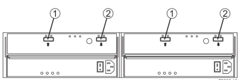
Drive Expansion Enclosure Rear Panel
The drive expansion enclosure connects to the RAID expansion enclosure(s) using serial-attached SCSI (SAS) cables (rather than fibre channel). Each RAID controller has one drive expansion connector (located on the far right of the controller). You can connect up to three optional drive expansion enclosures to your RAID controller/drive enclosure. Drive expansion modules (see Figure 1-5) use the following SAS connectors:
1. SAS in connector 2. SAS out connector
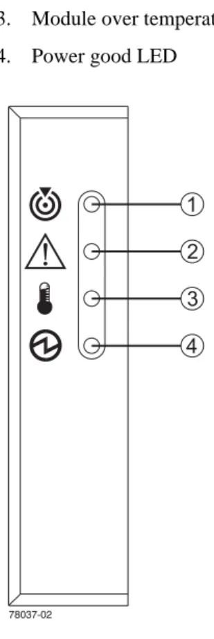
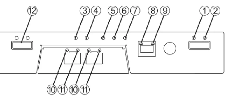
System Indicators
Expansion drive enclosures cable to the primary disk enclosure. The RAID controller/drive enclosure has a set of indicators on the front-left side that help you determine the operational status of the unit, see Figure 1-6.
1. Module locate LED 2. Service required LED
3. Module over temperature LED 4. Power good LED
The RAID Controller Module
Figure 1-7 identifies the indicators on the rear of a RAID controller module. 1. Link service action required (fault)
2. Link up
3. Battery service action required (fault) 4. Cache active
5. Service action allowed 6. Service action required 7. Controller power 8. Ethernet activity 9. Ethernet speed 10. Host channel speed 11. Host channel speed
12. Not used in this configuration
Figure 1-7 RAID Controller Rear Panel Indicators
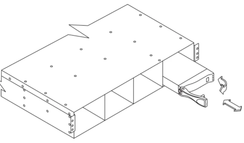
Drive Locations and Indicators
Each RAID enclosure or drive expansion enclosure holds up to 12 sled-mounted removable hard drives. At least two drives must be installed in the enclosure for it to operate.
Figure 1-8 Drive Extraction (Front) From the Enclosure The disk drive indicator LEDs have the following meanings: 1. Service action allowed (blue)
2. Service action required (yellow) 3. Disk drive active (green)
Powering On an IS-NAS Server
To power on a server or cluster, do the following: 1. Verify that all servers are switched off.
2. Beginning with expansion enclosures, start all storage subsystems.
3. Wait until the disk LEDs on all of the expansion enclosures have stopped blinking (which indicates that they are spinning up) or two minutes, whichever comes first.
4. Start the storage subsystem RAID controller enclosures.
The disk drives in some storage enclosures will not spin up until commanded to do so by the RAID controller. Consequently, the LEDs of those drives may continue to blink until after the RAID controller enclosure has sent those commands and the drives have spun up. 5. For a cluster configuration, or when using an external System Management Unit (SMU),
start the SMU by depressing the red button located on the right of the unit. 6. Wait one minute to allow the external SMU to start.
7. Power up the IS-NAS server or the first node in the cluster. To switch the power on for a server/node:
• If the power cables are not connected to the PSU, plug in the power cables. If, after 10 seconds, the PSU LEDs are lit but the Power Status LED on the rear panel is not lit, press the PWR button to restore power to the system boards.
• If the power cables are connected to the PSU, press the PWR button on the rear of the server.
The power button may be used to restore power to the system when the server is in a standby power state. Normally, when power cables are connected to the PSUs, the server will power up immediately. If, after 10 seconds, the LEDs on the power supplies are lit but the Power Status LED is not lit, press the PWR button to restore power to the system.
Note: Do not use the PWR button during normal operation of the server. Pressing this button will cause an improper shutdown: it immediately powers down the system, but the PSUs and system fans will continue to run.
8. If you are starting a cluster, wait 5 to 10 seconds before powering on the next node in the cluster.
Software Configuration
After your IS-NAS server is powered on, you can then configure the Software Management Unit (SMU), a web-based GUI to administer your IS-NAS server. This section describes how you access the web manager SMU and the items to be configured.
Accessing the Web Manager SMU
You can use one of the following web browsers to access the web manager SMU: • Microsoft Internet Explorer 7.0 (or later)
• Mozilla Firefox 1.5 (or later)
Some advanced features of SMU require Sun Microsystem’s Java Runtime Environment 5.0 Update 6 or later.
To access the web manager SMU, do the following:
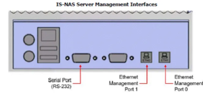
1. Connect a cross-over ethernet cable from a laptop or PC to the primary ethernet port (Port 0) on the IS-NAS server. See Figure 1-10.
Figure 1-10 Ethernet Connections on the IS-NAS Server 2. Launch a web browser to the following URL:
Note: The IS-NAS server may take two to three minutes (after the start of the power-up sequence) to fully come online and be reachable via your browser.
Table 1-6 shows the pertinent default settings.
After a successful login, the system displays the SMU home page, as shown in Figure 1-12. Table 1-6 Default Settings
Setting Default
Root password nasadmin
Manager password nasadmin
Admin password nasadmin
Admin EVS private IP address (eth1)
192.0.2.2
Admin EVS public IP address (eth0)
Figure 1-12 SMU Home Page
Configuring SMU for Your Environment
This section briefly describes the areas of setup and configuration using the following topics. • General setup and network settings
• File system configuration • Serving the file system • Documentation
The setup wizard is intended to be easy to use and leads you through the initial system configuration steps.
General Setup and Network Settings
Figure 1-13 SMU Administration Screen
Choose SMU Administration from the SMU home page for general SMU setup and network settings. On the SMU Administration screen, choose the SMU Setup Wizard and Management Network links, shown in Figure 1-13.
Setup Wizard
On the Setup Wizard page, you can change the following items: • Passwords
• DNS server setup • SMTP relay • Date and Time
Modifying IP Addresses of Service EVS
Figure 1-14 shows the path to the screen that allows you to change the EVS IP addresses to that of your network enviornment.
Email Alerts to SGI Global Services
A special profile, SupportProfile, is intended for customer support use and sends email alerts to SGI Global Services. This feature is enabled by default.
To configure your email alerts, use the following path to the Email Alerts Setup screen, as shown in Figure 1-15:
Home > Status & Monitoring > Email Alerts Setup
File System Configuration
Per customer order, some NAS systems are shipped with file systems already set up. If your system was not so ordered, you must create your file system. First, create a storage pool and then a file system using the Storage Management link from the home page. Figure 1-16 shows the resulting web page.
Serving the File System
Choose File Services from the home page if you need to serve your file system. Figure 1-17 shows the resulting web page.
Documentation
For a comprehensive set of documentation of SMU and the IS-NAS server, choose
Documentation from the home page. Figure 1-18 shows the documents that are available.
Figure 1-18 SMU Documentation Screen
After Software Configuration
Once you have completed the software configuration, the SMU software will instruct you to reboot the external SMU or the IS-NAS server.
To restart the IS-NAS server, use the following SMU links:
Contacting SGI
To contact the SGI Customer Service Center, call 1-800-800-4SGI, or visit http://www.sgi.com/support/customerservice.html.
From outside the United States contact your local SGI sales office. For more information on available SGI storage products, see: http://www.sgi.com/storage
To reach SGI for other purposes, use the following contact information: SGI Corporate Office
46600 Landing Parkway Fremont, CA 94538 http://www.sgi.com
North America +1 800.800.7441 Latin America +55 11.5185.2860 Europe +44 118.912.7500 Japan +81 3.5488.1811 Asia Pacific +1 650.933.3000