Installation Manual
BYD Wall-mounted AC Charging Box Installation Manual Version/Revision: A/0
Dedicated Service Commitment from BYD Auto
Dear valuable customers:
We are determined to strive for continuous improvement to ensure our products and services meet your requirement. Our commitments to our customers include the following:
I. We shall ensure that our charger is safe and user-friendly. II. Our maintenance service shall be of high quality of standard.
III. In the case of any doubt or requirement, we will respond actively in a timely manner.
IV. Your comments on our service quality are highly appreciated. We would also record your complaint in detail, if any and try to solve it as soon as possible.
Version Date: 201402
COPYRIGHT © 2013 BYD AUTO Industry Co., Ltd. ALL RIGHTS RESERVED.
No part of this manual and/or data herein may be reproduced or transmitted in any form or by any means, electronic or mechanical, including photocopying, recording, or information recording and retrieval system, for any purpose, without the express written permission of BYD AUTO Industry Co., Ltd.
BYD Wall-mounted AC Charging Box Installation Instruction Version/Revision: A/0
CONTENTS
Foreword ... 1
01 Introduction ... 2
1.1 Notes on symbols ... 2
1.2 Transportation ... 2
02 Installation Instruction ... 3
2.1 About safety ... 3
2.2 Installation environment condition... 4
2.3 Unpacking ... 6
2.4 Installation method ... 6
2.4.1 Installation steps ... 7
2.4.2 Cable installation ... 9
BYD Wall-mounted AC Charging Box Installation Instruction Version/Revision: A/0
Foreword
Thank you for choosing BYD wall-mounted AC Charging Box (hereinafter referred to as the Charging Box). For better use and maintenance of the Charging Box, please read and keep the user manual carefully.
The Charging Box is designed to charge BYD electric vehicle, which may be installed in a garage or on a parking lot. As the Charging Box contains a number of high voltage lines, low voltage lines and complicated electronic components, please do not disassemble or refit these lines and components, or any fault so caused thereby would not be covered by warranty provided by BYD, and any personal injury incurred not be of our liability.
This User Manual is provided ONLY to help you use this product properly, and shall not be construed as any specification of the product configuration. For the product configuration, please refer to the contract (if any) related to this product or contact your distributor. The illustrations provided in this Manual are for reference only. Actual auto may differ in appearance.
Model:
Serial No:
BYD Auto Industry Company Limited reserves the right to modify technical property and content in the user manual without restraint and prior notice.
For better service, please provide accurate contact method. In case of any change, please contact BYD authorized service station to update it in the system. Please keep informed of related national laws and regulations as well as your local policies.
BYD Wall-mounted AC Charging Box Installation Instruction Version/Revision: A/0
1.1 Notes on symbols
1. 2 Transportation
Transportation equipment used must withstand the weight of the Charging Box.
During transportation, please place the Charging Box in the direction indicated by the mark. Do not incline or invert it.
DANGER!
Improper handling during transportation may cause damage to the charging box!
Please consider barycentre or centre of gravity of a Charging Box and transport it in a correct way to avoid tilt, damage or injury to pedestrians.
DANGER!
The symbol indicates that improper operation might endanger user’s safety or cause severe damage to the product. Please read and observe notes on the symbol carefully.
WARNING!
The symbol indicates that improper operation might endanger user’s safety or cause major damage to the product. Please read and observe notes on the symbol carefully.
ATTENTION!
The symbol indicates that improper operation might endanger user’s safety or cause certain damage to the product. NOTICE!
BYD Wall-mounted AC Charging Box Installation Instruction Version/Revision: A/0
02
Installation Instruction
2.1 About safety
In this section, general installation specifications are provided, which must be complied with during the whole installation.
The section is prepared for product installer and covers installation procedure and installation notes of the product.
Please read the section carefully before installing and observe notes in the section during installation. Damage caused by improper operation or not following the instruction shall not be the liability of BYD.
It is assumed that installers are fully aware of electric installation and corresponding regulations.
Please read all safety notes. All operation of the Charging Box must be performed in strict compliance with the safety notes.
DANGER!
Improper operation may causes electric shock!
Incompliance with correct procedure might cause electric shock. Incompliance with the guide, operation instruction and safety notes might cause electric shock and severe injury.
NOTICE!
Warning signs must always be visible. In case of damage, please replace them immediately.
BYD Wall-mounted AC Charging Box Installation Instruction Version/Revision: A/0
2.2 Environment and conditions of installation
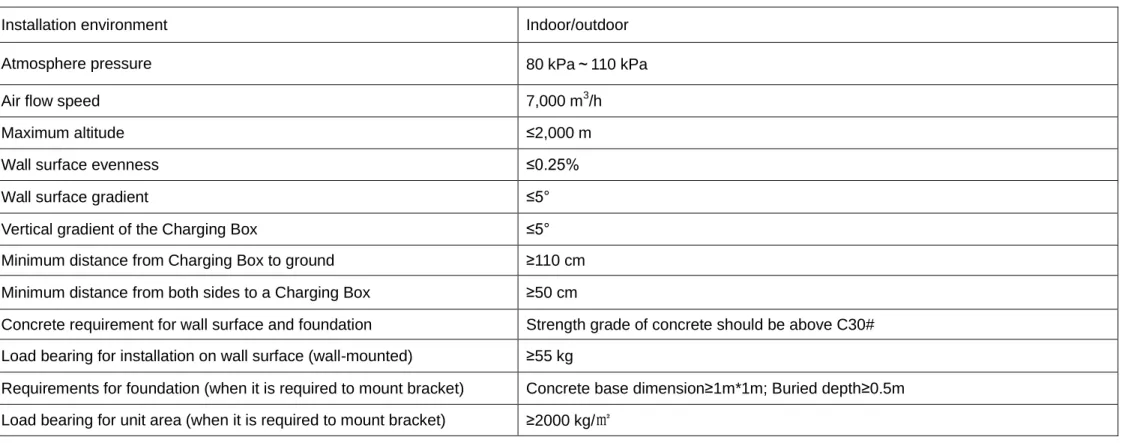
Table 2.1 environment and conditions for installation of the Charging Box
Installation environment Indoor/outdoor
Atmosphere pressure 80 kPa~110 kPa
Air flow speed 7,000 m3/h
Maximum altitude ≤2,000 m
Wall surface evenness ≤0.25%
Wall surface gradient ≤5°
Vertical gradient of the Charging Box ≤5°
Minimum distance from Charging Box to ground ≥110 cm Minimum distance from both sides to a Charging Box ≥50 cm
Concrete requirement for wall surface and foundation Strength grade of concrete should be above C30# Load bearing for installation on wall surface (wall-mounted) ≥55 kg
Requirements for foundation (when it is required to mount bracket) Concrete base dimension≥1m*1m; Buried depth≥0.5m Load bearing for unit area (when it is required to mount bracket) ≥2000 kg/㎡
For the safe operation of Charging Box, the installation site must meet the following conditions:
The installation location must be accessible at any time;
The Charging Box shall not be installed in places where there is severe vibration or explosive exists, such as inflammable gases, vapor or dust.
The Charging Box shall not be installed in places which are low-lying or easily waterlogged.
With good ventilation.
The installation location shall ensure convenience to observe indicators and operate.
BYD Wall-mounted AC Charging Box Installation Instruction Version/Revision: A/0
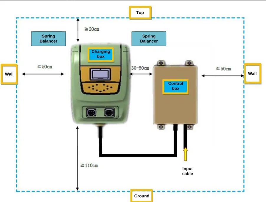
Wall Wall
Top
Spring Balancer
Spring Balancer
Ground Charging
box
Control box
Input cable
BYD Wall-mounted AC Charging Box Installation Instruction Version/Revision: A/0
2.3. Unpacking
Before unpacking, please make sure the box placed in the direction indicated by the sign.
Handle with care while unpacking.
Please confirm all materials in the packing box (refer to Attachment 1).
WARNING!
Please check the BOM in the packing box on the spot. In case of absence of certain parts, please contact your dealer immediately and do not install the Charging Box.
2.4 Installation method
Please prepare the tools as follows
Table2.2 Installation tools list
NO. Description NO. Description
1 Phillips screwdriver 5 Crimping Pliers
2 Monkey spanner 6 Wire stripping pliers
3 Sockets wrenches 7 φ 6 and φ 10 percussion drills
(in case of installing the stand columns, use φ 16)
4 Internal hexagonal wrench
DANGER!
Installation by non-professionals may cause danger!
BYD Wall-mounted AC Charging Box Installation Instruction Version/Revision: A/0
2. 4.1 Installation steps
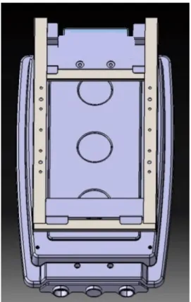
Step 1: Use four M8x50 expansion bolts to fix the installation bracket at A, B, C, D, as is shown in Fig. 2.2.(It is necessary to punch the wall in advance and the distance between A and ground is 1.3m.)
Diagram of installation bracket dimension(Unit in mm) Diagram of installation bracket dimension Fig. 2.2 Installation diagram of installation bracket
Step 2: Hang the Charging Box on the well-mounted installation bracket.
Step 3: Use two M6x20 screws to fix the Charging Box and the installation bracket.(at E and F)
Step 4: Use four M8x50 expansion bolts to fix the Control box as is shown in Fig. 2.3.
Step 5: Connect the cables of Charging Box to the inside of the control box, then connect the power cord to the control box. For detailed operation of cable installation, refer to “2.4.2 cable installation”.
M6х20
hexagon head screws
M8х50
expansion bolts (4pcs)
A B
C D
BYD Wall-mounted AC Charging Box Installation Instruction Version/Revision: A/0
Fig. 2.3 dimension of the control box (Unit in mm)
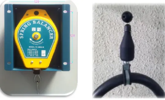
Step6:UseΦ 6 expansion rubber plug and M4 x20 Self-tapping screws to fix the spring balancer in the position shown in Fig. 2.1.
Step7:Fix the hook of the spring balancer to the hanging folders, and hang up the cables of the charging connector. The distance between the cables of hanging folders and charging connector is 1.5m.
BYD Wall-mounted AC Charging Box Installation Instruction Version/Revision: A/0
Fig 2.4 Spring balancer and cable clamp(Unit in mm)
Note: the installation method of wall-mounted charging box is above, if you choose the optional equipment of the mounting bracket of charging box, please refer to the Attachment 2: instruction for installation of the mounting bracket of charging box.
2.4.2 Cable installation
Installation requirement
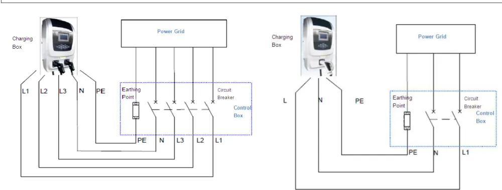
1) The charging box with three-phase input voltage, shall apply Three-phase Five-Wire System (TN-S) to its supply power; for the charging box with single-phase input voltage, the supply power shall be connected to L, N, and PE (in case of US single-single-phase 240 V, to L1, L2 and PE respectively). Cable color shall comply with the requirements of local standards.
2) The charging box shall be equipped with an independent distribution circuit without sharing it with other electrical products.
3) The input cable of the charging box shall be copper strand and the terminals shall be crimped as is required. (for detailed information, please refer to Attachment 1.)
4) To meet the requirements of protection class, the form of input cable entry of charging box shall be limited to the following two options: The input cable shall use type EVE or type EVT.
BYD Wall-mounted AC Charging Box Installation Instruction Version/Revision: A/0
Fig.2.3 list of multi-core cable requirements
Model Cable conductor Cable diameter In pipe or NOT Pipe diameter Remark
EVA080K 35mm2*5 42mm-48mm Not obligatory —— Use 75mm wrench to tighten the External
pressure type cable fixed head
EVA040K 16mm2*5 32mm-38mm Not obligatory ——
Use 62mm wrench to tighten the External pressure type cable fixed head.
EVA020K 16mm2*5 32mm-38mm Not obligatory ——
EVA015K 16mm2*3 No Yes 32mm-38mm
EVA007K 6mm2*3 No Yes 32mm-38mm
Use 62mm wrench to tighten the External pressure type cable fixed head.
In the case of using single-core copper strand wire, the wire shall be in pipe, and the pipe diameter is as follows: Fig.2.4 list of single-core cable requirements
Model Cable conductor Cable diameter In pipe or NOT Pipe diameter Remark
EVA080K 35mm2*5 No Yes 42mm-48mm Use 75mm wrench to tighten the External
pressure type cable fixed head
EVA040K 16mm2*5 No Yes
32mm-38mm Use 62mm wrench to tighten the External pressure type cable fixed head.
EVA020K 16mm2*5 No Yes
EVA015K 16mm2*3 No Yes
EVA007K 6mm2*3 No Yes
Note: the power input lines need to be crimped with tube type insulated terminals or copper terminals. WARNING!
During installation, do not alter any part in the Charging Box except the connecting terminal.
Please ensure reliable input earthing to avoid electric shock.
It is required that the torque is 3.5~4.5N.m when connecting the power input cable to the terminal of the Charging Box. Installation method:
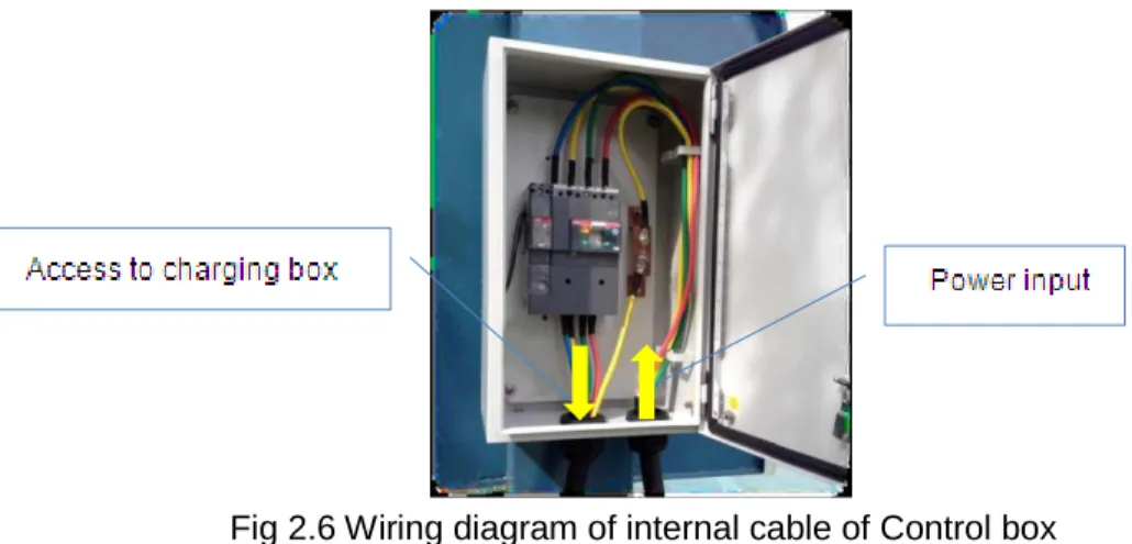
1) Connect the cables equipped in the Charging Box to the circuit breaker in the control box, and make sure the corresponding phase lines are correctly connected. Please refer to fig.2.5 and fig.2.6.
BYD Wall-mounted AC Charging Box Installation Instruction Version/Revision: A/0
breaker of the control box, while PE (yellow & green) is directly connected to the earthing terminals inside the control box, as is shown in fig.2.5 and fig.2.6. 3) For the single-phase input power Charging Box, connect the wiring harness of L, N, and PE(L1, L2, PE in the model EVA015KS/01) to the circuit breaker of
the control box, as is shown in fig.2.5 and fig.2.6. WARNING!
The input wire harness of the Charging Box must be connected correctly. The phase sequence should be in compliance with that marked on the input line of the Charging Box.
To avoid any over-heating, burning accidents and other phenomena due to poor contact, the cable and wire harness connection should be firm and reliable, also the screw should be tight.
Notice its I-direction when install the residual current circuit breaker.
BYD Wall-mounted AC Charging Box Installation Instruction Version/Revision: A/0
Fig 2.6 Wiring diagram of internal cable of Control box
Installation examination
When examining installation connection, all electric connection on site must be examined to ensure correct and firm connection. 1) Cable diameter in compliance with the requirements.
2) Ensure the reliable connection of the terminal.
3) Ensure torque at connection in compliance with the requirements. 4) Notice the I-direction of the residual current circuit breaker.
5) The nylon cable gland of the control box Input& Output cable should be lock without leaking.
6) After installation, the test insulation resistance value of input cable to ground(L1 to PE, L2 to PE, L3 to PE, N to PE) should be ≧30MΩ(Test voltage is DC 500V, testing time is1minute ).
7) Correct phase sequence connection. WARNING!
Missing some inspection items may cause danger!
BYD Wall-mounted AC Charging Box Installation Instruction Version/Revision: A/0
Attachment 1
Charging box mounting bracket installation instructions
Step 1: Take the Charging Box mounting bracket installation instructions as a reference to finish the installation
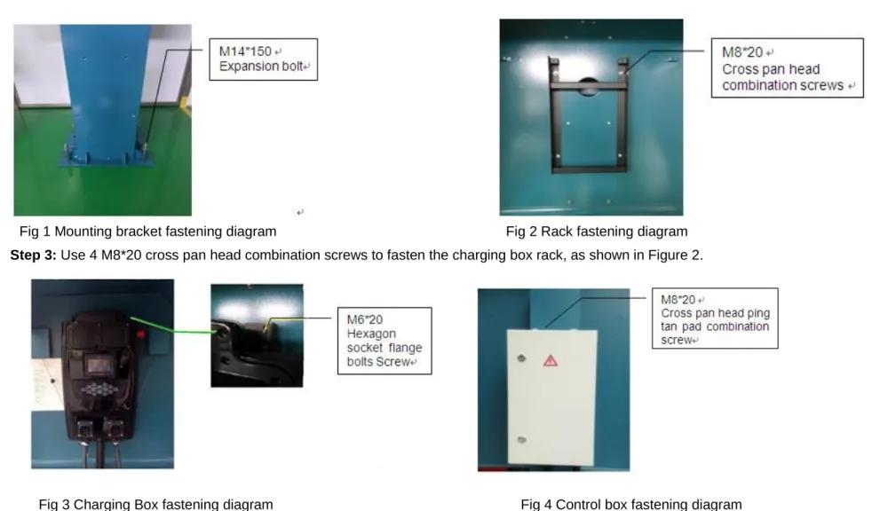
Step 2: Use 4 M14*150 expansion bolts to fasten the stand column of the mounting bracket on cement court, as shown in Fig 1.
Step 3: Use 4 M8*20 cross pan head combination screws to fasten the charging box rack, as shown in Figure 2.
Fig 3 Charging Box fastening diagram Fig 4 Control box fastening diagram Fig 1 Mounting bracket fastening diagram Fig 2 Rack fastening diagram
BYD Wall-mounted AC Charging Box Installation Instruction Version/Revision: A/0
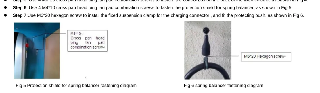
Step 4: Hang the wall-mounted Charging Box on the rack and use 2 M6*20 hexagon socket flange bolts to fasten the Charging Box, as shown in Fig 3. Step 5: Use 4 M8*20 cross pan head ping tan pad combination screws to fasten the control box on the back of the fixed column, as shown in Fig 4. Step 6: Use 4 M4*10 cross pan head ping tan pad combination screws to fasten the protection shield for spring balancer, as shown in Fig 5.
Step 7:Use M6*20 hexagon screw to install the fixed suspension clamp for the charging connector , and fit the protecting bush, as shown in Fig 6.
Step8 Cable installation, please refer to “2.4.2 Cable Installation” on page 14.
Step9 The power grid input cables should be came from a hole digged on the cement base and connected to the control box vertically. The position of the hole is shown as Fig 7。
Fig 6 spring balancer fastening diagram Fig 5 Protection shield for spring balancer fastening diagram
BYD Wall-mounted AC Charging Box Installation Instruction Version/Revision: A/0
Statement
BYD Wall-Mounted AC Charging Box set stated above shall not be used until officially delivered by Party B (supplier) and officially accepted by Party A (user). Otherwise, Party B shall not be liable for any result thereby.
BYD Auto Industry Company Limited.
Address: No. 3009, BYD Road, Pingshan New District, Shenzhen, Guangdong Province, P.R. China. Website: http://www.byd.com.cn
Tel: +86-0755-89888888
All information provided in this user manual are based on the latest data. BYD reserves the right to modify it without prior notice. BYD reserves the right of final explanation.
![Current Developments in our Understanding of Auditory Neuropathy ANSD [Auditory Neuropathy Spectrum Disorder]](data:image/gif;base64,R0lGODlhAQABAIAAAP///wAAACH5BAEAAAAALAAAAAABAAEAAAICRAEAOw==)