Copyright © 2014 Vilnius Gediminas Technical University (VGTU) Press Technika http://www.bjrbe.vgtu.lt
OF ROAD AND BRIDGE ENGINEERING ISSN 1822-427X / eISSN 1822-4288
2014 Volume 9(4): 241–250
doi:10.3846/bjrbe.2014.30 1. Introduction
The structural behaviour of cable-stayed bridges is very complex due to several factors. (1) These structures are highly statically redundant. (2) A tensioning process is re-quired to transfer the loads to the stay system. (3) Their structural system continuously changes during erection. (4) The structure is more flexible during erection as its structural system is not completed (Navratil, Zich 2013). All these factors make the simulation of the construc-tion process of cable-stayed bridges especially advisable to guarantee that safety, serviceability and design conditions are satisfied.
Traditionally, most of the simulation methods found in the literature are proposed for the cantilever erection met-hod (e.g. Wang et al. 2004). In fact, only few methods speci-fically designed for the simulation of the alternative erection technique, the temporary support erection method, are pre-sented. In this technique, the deck is first built on a set of temporary supports and then, the load of these supports is transferred to the stay system by a tensioning process.
Most methods presented in the literature to simu-late the tensioning process of cable-stayed bridges built on temporary supports (e.g. Lozano-Galant et al. 2012a,
2012b, 2013) assume that the superstructure is built in a single operation. Nevertheless, because of the limited re-sources available on site this is rarely true. This makes the staggered erection of the superstructure a common as-pect to consider in the construction of the vast majority of structures, especially in long-span bridges. The importan-ce of the erection proimportan-cess of the superstructure is not only economical. For example, the effects of the construction joints in the structural behaviour of the structures have been pointed out by many authors (Li et al. 2010; Veletzos, Restrepo 2011; Wang et al. 2014).
In a number of structures, staggered erection of su-perstructure modifies significantly the deformations and the stress-state throughout the tensioning process. Exam-ples of these effects are the changes in the lifting sequen-ce of the temporary supports during erection or the pre-sence of un-tolerable deformation and/or stresses during erection and/or in service. Analysing these effects is espe-cially important for a proper design of stay forces in servi-ce and to accurately simulate the tensioning proservi-cess, with the consequent improvement of the structural safety and cost reduction. Nevertheless, despite of its importance, little attention about the effects of the staggered erection
ModIfIcatIons of the stress-state of cable-stayed brIdges due
to staggered constructIon of theIr superstructure
Jose antonio lozano-galant1, lidia ruiz-ripoll2, Ignacio payá-Zaforteza3, José turmo4 1, 2Dept of Civil Engineering, Universidad de Castilla-La Mancha, Avda,
Camilo José Cela, s/n, 13071 Ciudad Real, Spain
3ICITECH, Dept of Construction Engineering, Universitat Politècnica de Valencia, Camino de Vera s/n, 46022 Valencia, Spain
4Dept of Construction Engineering, Universitat Politècnica de Catalunya, BarcelonaTech, c/ Jordi Girona 1-3, C1, 08034 Barcelona, Spain
E-mails: 1[email protected]; 2[email protected]; 3[email protected]; 4[email protected] abstract. In current practice, the effects of the evolutionary erection of cable-stayed bridge superstructure are rarely
included into the simulation of its tensioning process. In fact, stay forces in service are usually defined in early stages of design, when the construction process has not even been conceived in detail yet. In order to fill this gap, the effects of the evolutionary erection of cable-stayed bridge superstructure throughout the tensioning process are studied in this paper. This study is focused on steel cable-stayed bridges erected on temporary supports. For the very first time a new criterion to include the effects of the evolutionary erection of cable-stayed bridges into the definition of the stay forces in the service state is presented.
of cable-stayed bridge superstructure in the simulation process is paid in the literature. In fact, the definition of the stay forces in service rarely includes this effect. This paper aims to fill this gap by simulating the modifications in the deformation and stress-state of cable-stayed bridges caused by staggered erection of their superstructures. This initial study is focused on: (1) the construction of steel structures; (2) the temporary support erection technique; (3) deck construction with only longitudinal changes du-ring erection and without considedu-ring evolutionary cross sections; (4) on linear static analyses, so geometrical or me-chanical nonlinearities are not taken into account. Also, (5) time-dependent phenomena, such as steel cable relaxation, are also neglected. It is envisaged to develop this method in a Building Information Modelling Interface (Lin 2014) as well as to deal with concrete and composite bridges.
This paper is organized as follows. In Section 2, the effects of the staggered erection of the cable-stayed bridge superstructure are introduced into a forward simulation of the tensioning process. To illustrate these effects, academic and actual bridges are analysed. Furthermore, the effects of the main types of pylon-deck connections are studied. This section points out the two following problems: (1) the effect of the evolutionary erection of bridge superstructure needs to be included into the definition of the stay forces in service, and (2) a method to obtain directly the defor-mation and stress-state in service including the effect of the staggered erection of the bridge superstructure (that is to say, without the complete simulation of the tensioning process) is required. In Section 3, these two problems are solved by presenting a new criterion to include the effects of the staggered erection of the superstructure into the cal-culation of the stay forces and the stress-state in service. This criterion is based on the minimization of the bending energy of the structure. To illustrate the application of this criterion, a numerical example is presented. The main in-convenient of this criterion is that a numerical integration of the bending moment diagrams of the structure is requi-red. The solution to this problem is presented in Section 4, where a simplified method to calculate suitable strains in the stays and the stress-state in service is developed. To il-lustrate the application of this method, a numerical exam-ple is also presented in this section. This simplified method is based on the analysis of the stay forces and it is easily implemented with the help of simple computer software. In Section 5, some conclusions are drawn.
2. forward modelling of the tensioning process
The first step in the modelling of the construction process of any cable-stayed bridge is defining the target state to be achieved on service. This state, known as the Objective Ser-vice Stage (OSS), is characterized by a set of target forces in the stays, , under a certain target load as presented in Lozano-Galant et al. (2012a). Between all the criterions proposed to calculate these forces, the most common one is the Rigidly Continuous Beam Criterion (Lazar et al. 1972),
RCBC, in which the stay forces at the deck produce the same vertical component as an equivalent continuous beam.
With αn being the angle between the nth stay and the deck is directly obtained by projecting the vertical reaction of the corresponding fictitious support, Rn, into the stay direction as presented in Eq (1):
. (1)
Despite its importance, the effects of the staggered erection of the superstructure are rarely included in the definition of the stay forces in the OSS. In fact, these forces are defined in early stages of design, when the construc-tion process has not even been conceived in detail yet.
Once the stay forces in the OSS have been defined, the simulation of the tensioning process is carried out. This simulation is associated with a number of computational difficulties. Examples of these difficulties are that the lift-ing of the deck durlift-ing the tensionlift-ing sequence makes the calculation non-linear or the fact that each time a stay is pre-stressed the forces of the rest of stays are changed. Sev-eral researchers have recommended methods based on the backward approach to overcome these difficulties in the cantilever erection method (e.g. Wang et al. 2004) and in the temporary support erection method (Lozano-Galant et al. 2012a). In this approach, the configuration of any partial structure is determined by disassembling the bridge from the OSS according to the opposite erection sequence followed on site. The main inconvenient of this approach is the difficulty to correct deviations of the tensioning strat-egy on site. To overcome this problem, a forward model-ling has been proposed for the cantilever erection method (Wang et al. 2004) and the temporary supports erection method (the Forward Algorithm, FA, developed in Loza-no-Galant et al. 2012b). Compared to the modelling of ad-vanced commercial programs, the FA is easily reproduced in simple structural codes as the pre-stressing forces are modelled as imposed strains. The FA includes two iterative processes based on the superposition principle: (1) a local iterative process to simulate the lifting of the temporary supports, and (2) an overall iterative process to assure the achievement of the stay forces defined in the OSS at the end of the tensioning process. Recently, a new direct ap-proach has been presented in Lozano-Galant et al. (2013) to deal with concrete time-dependent phenomena effects (Bywalski, Kameski 2013; Kim et al. 2014).
In the applications of the FA presented in Lozano-Galant et al. (2012b) the effects of the staggered erection of the superstructure were not included. To include these effects into the simulation of the FA, the staggered erected superstructure were introduced as the initial stage of the tensioning process.
The pylon-deck connection plays an important role on the modifications throughout the tensioning process due to the staggered erection of the superstructure. To il-lustrate this, two academic examples with different pylon-deck connection (a cable-stayed bridge whose pylon-deck passes through the pylon legs and a bridge whose deck is anyhow linked with the pylon) are analysed in the following sec-tion. Then, the changes produced by the staggered erection of the superstructure of an actual bridge are presented. 2.1. academic examples
In this section two academic cable-stayed bridges, B3, and B2, described in Figs 1a–1b respectively, are analysed. The differences between these two structures are as follow: (1) different number of stays, three stays for B3 and two for B2, (2) different type of pylon-deck connection, no connec-tion in B3 and vertically simply supported in B2, and (3) different tensioning sequences.
For both structures, Young Modulus is assumed as 206 000 MPa for deck and pylon and 195 000 MPa for stays. Deck and pylon area and inertia are 1 m2 and 1 m4. Stays area is 0.003 m2. Negligible inertia of the stays is assumed. The stay forces in the OSS of both bridges are defined by the RCBC. The obtained parameters for a target load of 120 kN/m are summarized in Table 1.
The construction process of the superstructure of both bridges is defined as follows. Firstly, three simply sup-ported deck segments, with 20 m, 40 m and 20 m length respectively and dead loads of 80 kN/m are placed over three temporary supports forming two construction joints as presented in Fig. 1c. Then, both construction joints are welded to enable deck continuity. Next, the stays are pre-stressed to transfer the load from the temporary supports to the stay system. The tensioning sequence of both ex-amples is summarized in Table 2, in which the first row describes the tensioning stage, the second row the pre-stressed stay, and the third one the force, N, to be achieved by the jack on site. Finally, the rest of the permanent loads (40 kN/m) are applied and the OSS is achieved.
In Fig. 2 vertical deck deflections in the OSS obtained in B2 and B3 are compared with those of the target conti-nuous beam, B0. The max differences in bridges with pylon-deck connection are found at the stay-girder connections. This is appreciable in B2 where a max difference of 1.8 mm is obtained. These differences are increased in bridges with no pylon-deck connection, such as B3. In this case, the max differences, 15.2 mm, are located at the connection. To cor-rect these deviations and to reach the target geometry in the OSS, the deck segments can be pre-cambered.
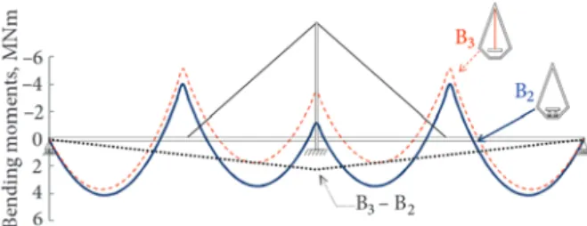
The bending moment diagrams in the OSS obtained in B2 and B3 are summarized in Fig. 3. This figure shows that the target continuous beam bending moment dia-gram, B0, is only obtained in those bridges with no pylon-deck connection, such as B3. In the case of bridges with pylon-deck connection, such as B2, the bending moment diagram presents lower hogging bending moments at the pylon-deck connection. The differences between B3 and B2 are distributed in a triangular diagram as presented by
the dotted line in Fig. 3. The max differences, with a value of 2246.98 kNm, are found at the pylon-deck connection. This value represents a deviation of 65.43% of the target
table 1. Parameters of the RCBC of B2 and B3
Stay (Example) Rn, MN αn, º Nn, MN S1 (B2 and B3) 2.74 40.36 4.24
S2 (B3) 2.22 90.00 2.22
S3 (B2 and B3) 2.74 40.36 4.24
table 2. Tensioning operations in B2 and B3
B2 B3
Stage 1 2 Stage 1 2 3
Stay 1 3 Stay 1 3 2
N, MN 3.61 4.20 N, MN 4.03 4.29 1.15
fig. 1. Academic examples: a − B3; b − B2; c − girder on temporary supports. Stays are named S1, S2 and S3
Note that bridge B2 has only two stays named S1 and S3, m
fig. 2. Differences between the vertical deflections obtained
in B2 and B3 in the deck in the OSS and the vertical deflections in the equivalent continuous beam, B0, mm
bending moment at that location. The triangular diagram of differences is produced by the fact that the vertical re-actions in the deck-pylon connection and abutments of B2 differ from those obtained in the equivalent continuous beam, B0. The presence of backstays will not modify these results. It is important to take into account that in the case of B2 no additional tensioning operations enable the achie-vement of the diagram of B0.
The bending moment diagrams produced by the ap-plication of a unitary strain in stays of both structures are presented in Fig. 4.
Fig. 4 shows that in structures where the deck is not connected with the pylon, such as B3, the ben-ding moments of all inner elastic supports are directly controlled by the pre-stressing of the stays. Therefore, the continuous beam behaviour is achieved in the OSS for all superstructure erection processes. Nevertheless, in structures with pylon-deck connection, such as B2, the pre-stressing of the stays cannot introduce hogging bending moments at the pylon-deck connection. For this reason, higher sagging bending moments are found at the pylon-deck connection and the continuous beam stress state cannot be achieved unless an imposed settle-ment is introduced in both abutsettle-ments. This settlesettle-ment produces a triangular diagram of hogging bending mo-ments that raises the bending moment diagram in the OSS. In the case of B2 a settlement of 5.7 mm is required to achieve the OSS at completion. Obviously, the intro-duction of this settlement modifies the imposed strain that have to be introduced in the stays to achieve their target force.
2.2. cable-stayed bridge in Wuxi
In this section, the conclusions obtained by the analysis of the academic examples are validated in the model of an ac-tual cable-stayed bridge. To do so, the cable-stayed bridge
presented in Fig. 5a is analysed. This bridge is a simplified model for a project of a cable-stayed bridge with 18 stays in the city of WuXi in China, X18. The bridge has a 55 m high steel pylon, a 180 m long steel box girder deck. The stays are arranged in a fan symmetrical form. The deck is vertically linked with the pylon. The dead loads of the girder and the pylon are 135 kN/m and 95 kN/m, respec-tively. Young Modulus is 206 000 MPa for deck and py-lon and 195 000 MPa for stays. Deck and pypy-lon area are 1.71 m2 and 1.22 m2. Deck and pylon inertia are 4.22 m4 and 11.30 m4. The stays area is 0.0072 m2. Null inertia in the stays is assumed.
The steel girder is erected on a set of 10 temporary supports placed every 15 m throughout the deck as presen-ted in Fig. 5b. The deck includes three construction joints: two of these joints span 45 m from abutments and the other one is located at the pylon-deck connection as presented in Fig. 5b. The cable-stayed bridge superstructure is staggered erected in a similar way to the academic bridges described in the preceding section. The stay forces in the OSS, NOSS, are calculated by the RCBC. The obtained stay forces for a target load of 205.5 kN/m are summarized in Table 6.
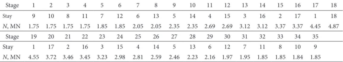
To comply with the limit stresses during the tensi-oning process, the pre-stressing of the stays is defined in two stages. In the first tensioning operation all stays but one are installed in alternative sides of the pylon from the pylon to the abutments with the 85% of that force defined in the OSS. In the second tensioning operation, the forces of all stays are adjusted in alternative sides of the pylon from the abutments to the pylon. The force that has to be introduced by the jack in the second tensioning operation to assure the achievement of the OSS is calculated by the FA. This tensioning sequence is summarized in Table 3, in which the first row describes the tensioning stage, the second row the stay that is prestressed, and the third one the force, N, to be achieved by the jack on site.
fig. 4. Bending moments produced by unitary strains in stays S1, S2 and S3 in cable-stayed bridges B3 (a) and B2 (b)
The evolutionary erection of the superstructure inf-luences the deformation and stress state in the OSS. This is clearly appreciable in Fig. 6 where the bending moment diagram obtained in the OSS is presented by a continuous line. The differences with the target continuous beam dia-gram, X0, are presented by a dotted line in the same figu-re. As in the previous academic example, these differences are distributed in a triangular diagram, with a max value of 760.12 kNm located at the pylon-deck connection. This value represents a deviation of the 54.8% of the target ben-ding moment at that location. A pre-camber is required in the steel beams to guarantee the achievement of the target vertical deflections in the OSS.
The evolutionary erection of the superstructure also affects the deformation and stress state during the tensio-ning process. Therefore, an adequate modelling is adequ-ate to assure that safety thresholds are not exceeded. A peculiarity of the temporary support erection method is that the evolutionary erection of superstructure affects the vertical reactions of the temporary supports. Therefore, the lifting sequence of the deck depends, to a great extent, on the tensioning process. In order to study this effect, the obtained vertical reactions have been compared with those calculated assuming no construction joints. These results are summarized in Fig. 7, where the evolution of reactions in two temporary supports (T3 and T4) is presented. The first temporary support, T3, highlighted by the dotted line, corresponds to the location of one of the construction joints. The other temporary support, T4, highlighted by the continuous line, corresponds to the adjacent support.
Fig. 7 shows how the placement of the construction joints decreases the vertical reaction of T3 and increases the vertical reaction of T4, 436.20 kN and 277.81 kN re-spectively. Compared to the continuous beam reactions, these values represent a deviation of the 23.13% in T3 and 13.76% in T4. Throughout the tensioning process these differences are modified. In addition to the change in val-ue of these reactions, superstructure erection also influ-ences the lifting sequence. This is appreciable by the evolu-tion of vertical reacevolu-tion in T3. This support is lifted, that is null vertical reaction, in Stage 8, when the effect of the superstructure erection is included, and in Stage 9, when it is not. The value of the reactions on site is measured by load cells. It is important to take into account that knowing both the actual reaction of the temporary supports and the lifting sequence is important to simulate more accurately
the actual structure, with the consequent improvement of the structural safety.
3. criterion to define OSS including the evolutionary construction of superstructure
As shown above, defining the stress-strain state of cable-stayed bridges in service neglecting the staggered erection effects might result in considerable inaccuracies (e.g. the bending moments differences are higher than 50% in the presented example). Nevertheless, few studiesabout the influence of the staggered erection of the superstructure in the definition of the OSS have been presented in the lit-erature. To fill this gap, a new criterion to include the effect of staggered construction of the cable-stayed bridge super-structure in the OSS is presented in this section. This cri-terion is based on the minimization of the bending energy of the structure and enables the determination of a set of imposed strains in the stays that include the effects of stag-gered erection of the cable-stayed bridge superstructure. A simplified method to define these strains from the analysis of the stay forces is also proposed.
3.1. Minimal bending energy criterion
Several simplified criteria are proposed to define the stay forces in the OSS by minimizing the bending energy of the
table 3. Tensioning operations of the bridge in WuXi
Stage 1 2 3 4 5 6 7 8 9 10 11 12 13 14 15 16 17 18
Stay 9 10 8 11 7 12 6 13 5 14 4 15 3 16 2 17 1 18
N, MN 1.75 1.75 1.75 1.75 1.85 1.85 2.05 2.05 2.35 2.35 2.69 2.69 3.12 3.12 3.37 3.37 4.45 4.87
Stage 19 20 21 22 23 24 25 26 27 28 29 30 31 32 33 34 35
Stay 1 17 2 16 3 15 4 14 5 13 6 12 7 11 8 10 9
N, MN 4.55 3.72 3.46 3.45 3.23 2.98 2.81 2.59 2.46 2.23 2.16 1.97 1.95 1.85 1.85 1.84 1.85
fig. 6. Bending moments in the OSS in X18 (continuous line) and differences with X0 (dotted line)
fig. 7. Evolution of vertical reaction in two supports with
structure (see e.g. Du 1989). Other authors, (Aboul-Ella 1990; Hegab 1986, 1987) have presented iterative process-es for the analysis of cable-stayed bridgprocess-es based on the po-tential energy.
If the shear energy is neglected, the energy of the structure, W is expressed as the sum of the bending en-ergy, WB, and the axial energy, WN, multiplied by a weight coefficient, φ, chosen to be the cost ratio between bending and axial energy. With E being the elasticity modulus, the inertia, and the area of the different elements of the struc-ture (girder − G, pylon − P, and stays − S), the bending and axial energy is expressed in terms of the bending mo-ments, M, and the axial forces, NF, as presented in Eq (2):
. (2)
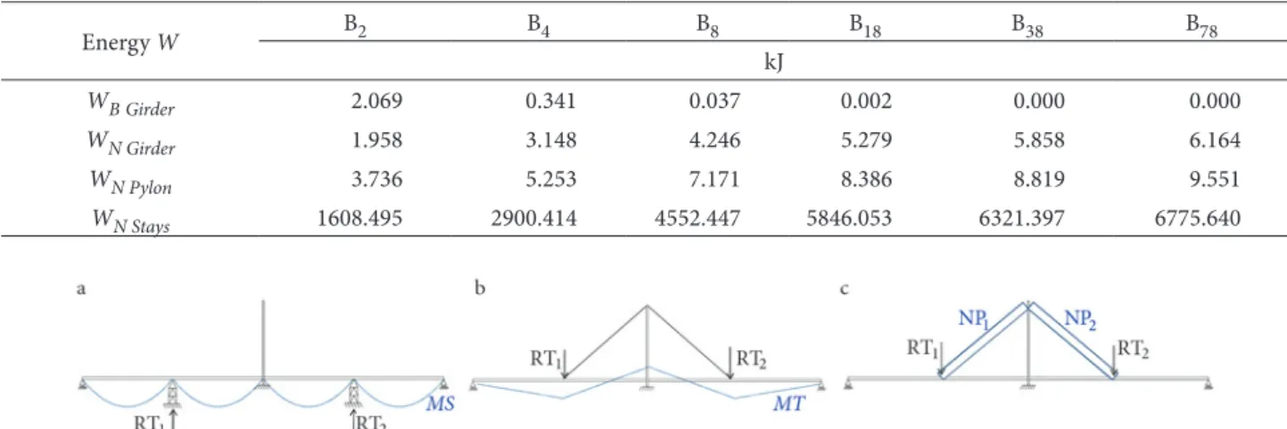
In order to study the influence of the number of stays into the energy of the structure, bending and axial ener-gies of different bridges with 2, 4, 8, 18, 38 and 78 stays under dead loads are presented in Table 4 (B2, B4, B8, B18, B38, B78). These bridges are identical (same loads, dimen-sions and mechanical properties) to B2. Only the number and area of the stays are different. In these bridges, the stays areas are 0.003 m2, 0.0024 m2, 0.0012 m2, 0.0006 m2, 0.0003 m2 and 0.00015 m2, respectively. All these struc-tures are erected in a single stage (that is to say, without staggered erection of their superstructure). It is to highlight that WB Pylon and WB Stays are null because of the sym-metry of the structure and the negligible inertia of the stays, respectively.
The analysis of Table 4 shows that, because of their reduced area, most of the energy in cable-stayed bridges is located in the stays. Furthermore, the higher the num-ber of stays: (1) the higher the energy in the structure, (2) the bigger the axial energy in the deck, pylon and stays, and (3) the smaller the bending energy in the deck. All these facts serve to conclude that minimizing the energy
function including the axial energy leads to the min pre-stressing force in the stays. Nevertheless, this configura-tion provides inappropriate bending moment distribu-tions in the deck. In addition, it is important to take into account that the axial energy is economically counterbal-anced if the effects of the nonlinear instabilities, such as buckling, are prevented. For all these reasons, the energy criterion presented in this section has only been based on the bending energy and the effects of the axial energy have been neglected. This is equivalent of using a coefficient φ = 0. In doing so, the energy of the structure (in Eq (2)) is expressed as the sum of the bending energy of the girder and pylon as in Eq (3):
. (3)
The bending moment M(s), in a certain point s of the structure is expressed as a linear combination of a passive bending moment MP(s) and an active one MA(s) at the same point. The active bending moment is defined as the sum of the bending moments, M(s)εn produced by im-posed strains, εn, in all N stays as presented in Eq (4):
. (4)
The evolutionary erection of the superstructure is easily introduced into the definition of MP(s) as presented in Eq (5).
, (5)
where MS(s) includes the bending moment obtained at the end of the staggered erection of the superstructure. The obtained MS(s) for a staggered erection of four deck segments is presented in Fig. 8a. This staggered erection produces some reactions in the temporary supports RTi. On the other hand, MT(s) represents the bending moment
table 4. Energy of the elements of each bridge under dead loads
Energy W B2 B4 B8 B18 B38 B78
kJ
WBGirder 2.069 0.341 0.037 0.002 0.000 0.000
WN Girder 1.958 3.148 4.246 5.279 5.858 6.164
WN Pylon 3.736 5.253 7.171 8.386 8.819 9.551
WN Stays 1608.495 2900.414 4552.447 5846.053 6321.397 6775.640
produced when the temporary supports of the staggered erected superstructure are removed and their reactions, RTi, are transferred to the stay system. The obtained MT when temporary supports of Fig. 8a (RT1and RT2) are re-moved is presented in Fig. 8b.
The application of a unitary strain into the nth stay εn produces a bending moment M(s)n in each section, s of the girder and the pylon. These bending moments are used to define a set of coefficients of δn,j and ∆n,j. The former coefficient (δn,j) represents the bending energy obtained when unitary strains are applied in stays n and j. δn,j is calculated by numerical integration as presented in Eq (6). This equation provides a set of N2 terms. The latter coef-ficient (∆n,j) represents the bending energy produced by a unitary strain in stay n and the passive bending moments MP defined above. The numerical integration of this coef-ficient is presented in Eq (7) in which E(s) and I(s) are the Young Modulus and the Inertia in section s. This equation provides a set of N different terms.
, (6)
. (7)
According to the procedure presented in Du (1989), εn, MP and coefficients δn,j and ∆n,j are used to rearrange Eq (3) as in Eq (8).
. (8)
The target strainsεn obtained when the bending en-ergy of Eq (8) under dead load is minimal. This min is obtained by setting the partial derivative equal to zero as presented in Eq (9). The obtained system of equations is expressed in matrix form as presented in Eq (10):
, (9)
. (10)
In which ε the vector of target strains in the stays (N × 1 size), Δ is the vector (N × 1 size) that includes all the coefficients and [δ] is a symmetrical matrix (N × N size) that includes all the δn,j. As the only unknown of this equation is ε, this can be easily calculated by the inverse of matrix [δ], ([δ]‒1) as presented in Eq (11). The higher val-ues of this matrix are found in terms located in the main diagonal (examples in Section 3.2). Therefore, no row of
the matrix can be expressed as a linear combination of the other rows of the matrix and therefore, [δ]‒1 usually exists. . (11)
After these strains are obtained, the bending mo-ments, axial forces and deflections in the OSS are easily calculated. One of the important aspects of this method is that this way of calculating the OSS enables to include the effect of the evolutionary erection of the superstructure without the need of running all the tensioning process. However, the main inconvenient of this method is that a numerical integration is required.
It is to highlight that the bending energy of the pylon is zero for symmetrical structures. In non-symmetrical ca-ble-stayed bridges, the bending energy of the pylon plays an important role in the determination of the imposed strains in the backstays.
3.2. numerical application of the Minimal bending energy criterion
To illustrate the application of the Minimal Bending Energy Criterion, the academic examples B2 and B3 are analysed in this section. The integrals of Eq (6) and Eq (7) have been solved numerically through the beam elements, which form the finite element model of the girders of both bridges.
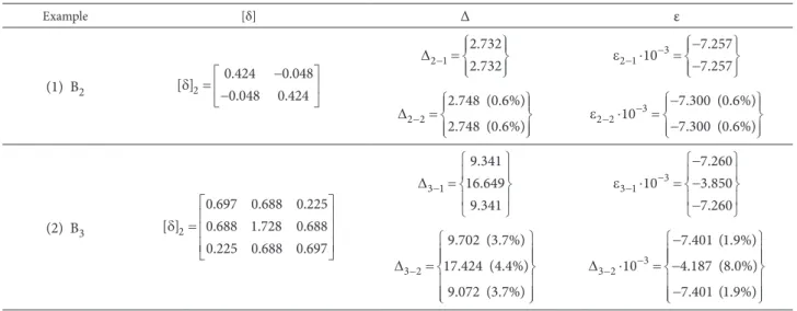
To analyse the effect of the evolutionary erection of the superstructure in the different parameters of the Mini-mal Bending Energy Criterion, both structures are anal-ysed for two different erection processes. On the one hand, the first erection process (B2‒1 and B3‒1) assumes that the superstructure is built in a single operation over the form-work (that is without staggered erection). On the other hand, the second construction process (B2‒2 and B3‒2) includes the staggered erection of the superstructure de-scribed in Fig. 1c. The obtained parameters are summa-rized in Table 5. It is to highlight that this table includes the percentage (in brackets) of differences between param-eters of different erection processes.
Table 5 shows that [δ] does not depend on how the superstructure is erected, as it only includes the effect of the pre-stressing of the stays (Eq (6)). This is to say, that [δ] takes into account the effect of the pre-stressing of the stays in the final structure. Thus, the effect of the stag-gered erection of the superstructure is included in vec-tor Δ (Eq (7)), and consequently in vecvec-tor ε (Eq (10)). Compared with B2-1, the staggered erection of the super-structure of B2‒2 produces an increment of the 0.6% in vectors Δ and ε. These differences are increased in B3. In this case, the max increments (4.4% in Δ and 8.0% in ε) are found in the second stay, S2. These results show that higher strains in stays are required to pre-stress them when the effect of the staggered erection of the super-structure is included.
of the erection process, stay forces defined by the Rigidly Continuous Beam Criterion produce the min bending energy in the structure, even though the bending moment diagram depends on the construction process and it does not have to match the bending moment diagram of the continuous beam. Albeit reasonable, this had not been tes-ted before. Compared to the complete simulation of the tensioning process, the Minimal Bending Energy Criteri-on reduces the computatiCriteri-on time as no iterative processes are required. Nevertheless, the main problem of this met-hod is that a numerical integration is required. Therefore, a simplified method to define the suitable imposed strains in the stays and the stress state in the OSS including the effect of the staggered erection of cable-stayed bridge su-perstructure is proposed in the following section. 4. simplified method
In view of the results, assuring the stay forces obtained by the RCBC in the OSS is equivalent of minimizing the bending energy in the structure for any staggered erection of the superstructure. Based on this assumption, the sim-plified method presented in this section enables to define the suitable strains in the stays and to simulate modifica-tions in stress-state in service without the need of numeri-cal integration.
Unlike the minimal bending energy criterion, the simplified method is based on the analysis of the stay forc-es. The target force in the nth stay to be achieved in the OSS, is defined as the sum of a passive force NPn and an active one, NAn, as presented in Eq (12) or alternatively in matrix form as in Eq (13):
, (12)
. (13)
The vector of target stay forces in the OSS, NOSS, is be calculated as a sum of a vector of passive stay force, NP, and the effect of the pre-stress. Vector NP includes the ef-fect of the evolutionary erection of the superstructure. The calculation of these forces are summarized by the follow-ing two steps. Firstly, the superstructure is staggered erect-ed (Fig. 8a). After these stages, some vertical reactions appear in the temporary supports (RT1 and RT2). Then, these temporary supports are removed from the structure and their reactions are transferred to the stay system. In this stage, some passive forces, NP, appear in the stays to counterbalance the reactions as in Fig. 8c.
The effect of the stay pre-stressing, NA, is defined by the product of an Influence Matrix [IM] and a vector of imposed strains in the stays, ε. On the one hand, [IM] shows how the axial forces in all the stays vary when a uni-tary strain is introduced into each stay. On the other hand, includes the suitable strains of the stays. As in the case of the Minimal Bending Energy Criterion, is the only un-known in Eq (13). This vector is defined by the inverse of [IM]as presented in Eq (14). As the higher increment of forces are found in the stay being prestressed, the higher numerical values of [IM]are found in terms located in the main diagonal. Therefore, as no row is expressed as a linear combination of other rows, [IM]‒1 usually exits.
. (14)
The simplified method is implemented easily with the help of a simple structural analysis software (that includes the simulation of imposed strains in the stays) as no numer-ical integration is required. To do so, the input data (geo-metrical and mechanical properties of the bridge, staggered erection of the superstructure, location of the temporary supports and loads) is first introduced. Secondly, the verti-cal reactions, RT, of the temporary supports after staggered
table 5. Numerical values of the parameters of the Minimal Bending Energy Criterion without (1) and including (2) the effect of the
staggered erection of the superstructure for B2 and B3. [δ] and Δ are in kNm
Example [δ] Δ ε
(1) B2
erection of the superstructure are calculated as presented in Fig. 8a. Thirdly, the passive stay forces, NP, are calculated as presented in Fig. 8c. Next, the [IM] is calculated by in-troducing unitary imposed strains in each stay. Finally, ε is calculated as presented in Eq (14. The steps of the procedure are summarized in the flow chart presented in Fig. 9. 4.1. numerical application of the simplified Method To illustrate the application of the Simplified Method, the cable-stayed bridge in WuXi is analysed in this section ac-cording to two different erection processes: (1) without staggered erection of the superstructure and (2) with stag-gered erection of the superstructure.
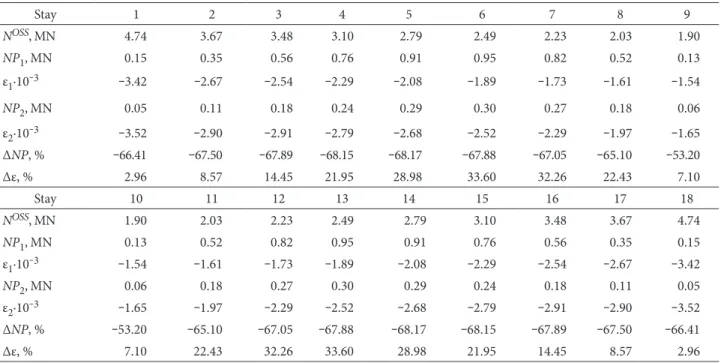
The [IM] and the stay forces in the OSS, NOSS, do not depend on the staggered erection of the superstructure. [IM] depends on the geometrical and mechanical proper-ties of the cable-stayed bridge. In addition to this, NOSS alsodepends on the target loads as presented in Section 2. These forces are presented in Table 6.
The rest of parameters of Eq (13) (NP and ε) are influ-enced by the staggered erection of the superstructure. The passive stay forces for both erection processes, NP1 and NP2, and the obtained strains for both erection processes, ε1 and ε2, for the different stays are presented in Table 6.
Table 6 also includes the percentage differences in terms of passive stay forces, , strains, , between both erection processes calculated as presented in Eqs (15) and (16).
, (15)
. (16)
The max differences are −68.17% for the passive stay forces (in stays 5 and 14) and 33.60% in strains (in stays 6 and 13). These values show that the effect of the staggered erection of the superstructure plays an important role in the imposed strains of the stays.
5. conclusions
1. A criterion to include the effects of the staggered erec-tion of cable-stayed bridge superstructure into the defini-tion of the Objective Service Stage has been presented. This criterion minimizes the bending energy of the structure.
2. The minimal bending energy is achieved when the stay forces in service produce the same vertical reactions than an equivalent continuous beam.
3. A method based on a numerical integration of ben-ding moment diagrams has been proposed to determine the imposed strains in the stays and the stress-state at the Objective Service Stage.
4. A simplified method based on the stay forces has been presented to determine the imposed strains in the stays and the stress-state at the Objective Service Stage. The advantage of this method is that it is easily implemented
fig. 9. Flow chart of the simplified method
table 6. Stay forces in the OSS, passive forces in the stays and suitable strains without (1) and including (2) the effect of the staggered erection of the superstructure for the bridge in WuXi and percentage differences
Stay 1 2 3 4 5 6 7 8 9
NOSS, MN 4.74 3.67 3.48 3.10 2.79 2.49 2.23 2.03 1.90 NP1,MN 0.15 0.35 0.56 0.76 0.91 0.95 0.82 0.52 0.13
ε1·10‒3 ‒3.42 ‒2.67 ‒2.54 ‒2.29 ‒2.08 ‒1.89 ‒1.73 ‒1.61 ‒1.54
NP2,MN 0.05 0.11 0.18 0.24 0.29 0.30 0.27 0.18 0.06
ε2·10‒3 ‒3.52 ‒2.90 ‒2.91 ‒2.79 ‒2.68 ‒2.52 ‒2.29 ‒1.97 ‒1.65
ΔNP, % ‒66.41 ‒67.50 ‒67.89 ‒68.15 ‒68.17 ‒67.88 ‒67.05 ‒65.10 ‒53.20
Δε, % 2.96 8.57 14.45 21.95 28.98 33.60 32.26 22.43 7.10
Stay 10 11 12 13 14 15 16 17 18
NOSS, MN 1.90 2.03 2.23 2.49 2.79 3.10 3.48 3.67 4.74 NP1,MN 0.13 0.52 0.82 0.95 0.91 0.76 0.56 0.35 0.15
ε1·10‒3 ‒1.54 ‒1.61 ‒1.73 ‒1.89 ‒2.08 ‒2.29 ‒2.54 ‒2.67 ‒3.42
NP2,MN 0.06 0.18 0.27 0.30 0.29 0.24 0.18 0.11 0.05
ε2·10‒3 ‒1.65 ‒1.97 ‒2.29 ‒2.52 ‒2.68 ‒2.79 ‒2.91 ‒2.90 ‒3.52
ΔNP, % ‒53.20 ‒65.10 ‒67.05 ‒67.88 ‒68.17 ‒68.15 ‒67.89 ‒67.50 ‒66.41
with the help of simple structural analysis software as no numerical integration is required.
5. The minimum possible bending energy in the deck of a cable-stayed bridge corresponds with that of an equi-valent fictitious and continuous beam. Independently of how the superstructure is erected, this minimum energy is always achieved in the OSS of structures with no pylon-deck connection. However, reaching the minimum ben-ding energy might imply large vertical deflections in the deck. Hence, to correct these and to reach the target geo-metry, providing a pre-camber to the deck segments might be advisable.
6. In the case of cable-stayed bridges with pylon-deck connection, the superstructure erection affects the stress state of the Objective Service Stage. The presence of cons-truction joints in the deck increases the bending energy of the structure in the Objective Service Stage. In this case, imposed settlement in abutments might be necessary. acknowledgements
The authors wish to thank the Ministerio de Econo-mia y Competitividad, the Ministerio de Ciencia e In-novación and the Junta de Comunidades de Castilla-La Mancha (Spain) for the funding provided through the research projects BIA2013-47290-R, BIA2009-13056 and PII2I09-0129-4085 directed by Jose Turmo and founded with FEDER funds.
references
Aboul-Ella, F. 1990. New Iterative Analysis of Cable-Stayed Structures, Computers & Structures 40(3): 549‒554. http://dx.doi.org/10.1016/0045-7949(91)90225-B
Bywalski, C.; Kaminski, M. 2013. Rheological Strains in Concrete Modified with Steel Fibre Reinforcement, Journal of Civil En-gineering and Management 19(5): 656‒664.
http://dx.doi.org/10.3846/13923730.2013.803497
Du, G. H. 1989. Optimal Cable Tension and Construction Ten-sioning of Cable-Stayed Bridges, Bridge Construction 11‒17. (in Chinese).
Hegab, H. 1987. Energy Analysis of Double-Plane Cable-Stayed Bridges, Journal of Structural Engineering 113(10): 2174‒2188. http://dx.doi.org/10.1061/(ASCE)0733-9445(1987)113:10(2174) Hegab, H. 1986. Energy Analysis of Cable-Stayed Bridges,
Jour-nal of Structural Engineering 112(5): 1182‒1195.
http://dx.doi.org/10.1061/(ASCE)0733-9445(1986)112:5(1182) Kim, T. H.; Kim Y. J.; Shin, H. M. 2014. Performance Assessment
of Precast Concrete Pier Cap System, Computers and Concrete 13(4): 501‒516. http://dx.doi.org/10.12989/cac.2014.13.4.501 Lazar, B. E.; Troitsky, M. S.; Douglas, M. C. 1972. Load Analysis
Balancing of Cable Stayed Bridges, Structural Division ASCE 92(8): 1725‒1740.
Li, L. G.; John, Z. G.; Oesterle, R. G. 2010. Improved Longitudi-nal Joint Details in Decked Bulb Tees for Accelerated Bridge Construction: Fatigue Evaluation, Journal of Bridge Engineer-ing 15(5): 511‒522.
http://dx.doi.org/10.1061/(ASCE)BE.1943-5592.0000097 Lin, Y. C. 2014. Construction 3D BIM-Based Knowledge
Man-agement System: a Case Study, Journal of Civil Engineering and Management 20(2): 186‒200.
http://dx.doi.org/10.3846/13923730.2013.801887
Lozano-Galant, J. A.; Turmo, J. 2014a. Creep and Shrinkage Ef-fects in Service Stresses of Concrete Cable-Stayed Bridges, Computers and Concrete 13(4): 483‒499.
http://dx.doi.org/10.12989/cac.2014.13.4.483
Lozano-Galant, J. A.; Turmo, J. 2014b. An Algorithm for Simula-tion of Concrete Cable-Stayed Bridges Built on Temporary Supports and Considering Time Dependent Effects, Engi-neering Structures 79: 341–353.
http://dx.doi.org/10.1016/j.engstruct.2014.08.018
Lozano-Galant, J. A.; Dong, X.; Payá-Zaforteza, I.; Turmo, J. 2013. Direct Simulation of the Tensioning Process of Cable-Stayed Bridges, Computers and Structures 121: 64‒75. http://dx.doi.org/10.1016/j.compstruc.2013.03.010
Lozano-Galant, J. A.; Payá-Zaforteza, I.; Dong. X.; Turmo, J. 2012a. Analysis of the Construction Process of Cable-Stayed Bridges Built on Temporary Supports, Engineering Structures 40: 95−106. http://dx.doi.org/10.1016/j.engstruct.2012.02.005 Lozano-Galant, J. A.; Payá-Zaforteza, I.; Dong, X.; Turmo, J.
2012b. New Algorithm to Model the Construction Process of Cable-Stayed Bridges Built on Temporary Supports, Engi-neering Structures 40: 119‒130.
http://dx.doi.org/10.1016/j.engstruct.2012.02.022
Navratil, J.; Zich, M. 2013. Long-Term Deflections of Cantilever-Seg-mental Bridges, The Baltic Journal of the Road and Bridge Engi-neering 8(3): 190‒195. http://dx.doi.org/10.3846/bjrbe.2013.24 Veletzos, M. J.; Restrepo, J. I. 2011. Modeling of Jointed Con-nections in Segmental Bridges, Journal of Bridge Engineering 16(1): 139‒147.
http://dx.doi.org/10.1061/(ASCE)BE.1943-5592.0000112 Wang, P. H.; Tang, T.; Zheng, H. 2004. Analysis of Cable-Stayed
Bridges during Construction by Cantilever Method, Comput-ers & Structures 82(4‒5): 329‒346.
http://dx.doi.org/10.1016/j.compstruc.2003.11.003
Wong, J. C. K.; Lee, Y. Y.; Lo, Y. T.; Wong, K. W.; Lueng, A. Y. T.; Fok, W. K.; Lam, H. F.; Wong, C. K.; Yie, C. Y. E. 2014. The Correlation between the Noise and Vibration Induced by a Bridge Movement Joint, The Baltic Journal of the Road and Bridge Engineering 9(3): 208‒214.
http://dx.doi.org/10.3846/bjrbe.2014.26