Corporate Headquarters Cisco Systems, Inc. 170 West Tasman Drive San Jose, CA 95134-1706 USA
http://www.cisco.com Tel: 408 526-4000
800 553-NETS (6387) Fax: 408 526-4100
Cisco Content Services Switch
Redundancy Configuration Guide
Software Version 8.10November 2005
THE SPECIFICATIONS AND INFORMATION REGARDING THE PRODUCTS IN THIS MANUAL ARE SUBJECT TO CHANGE WITHOUT NOTICE. ALL STATEMENTS, INFORMATION, AND RECOMMENDATIONS IN THIS MANUAL ARE BELIEVED TO BE ACCURATE BUT ARE PRESENTED WITHOUT WARRANTY OF ANY KIND, EXPRESS OR IMPLIED. USERS MUST TAKE FULL RESPONSIBILITY FOR THEIR APPLICATION OF ANY PRODUCTS.
THE SOFTWARE LICENSE AND LIMITED WARRANTY FOR THE ACCOMPANYING PRODUCT ARE SET FORTH IN THE
INFORMATION PACKET THAT SHIPPED WITH THE PRODUCT AND ARE INCORPORATED HEREIN BY THIS REFERENCE. IF YOU ARE UNABLE TO LOCATE THE SOFTWARE LICENSE OR LIMITED WARRANTY, CONTACT YOUR CISCO REPRESENTATIVE FOR A COPY.
The Cisco implementation of TCP header compression is an adaptation of a program developed by the University of California, Berkeley (UCB) as part of UCB’s public domain version of the UNIX operating system. All rights reserved. Copyright © 1981, Regents of the University of California.
NOTWITHSTANDING ANY OTHER WARRANTY HEREIN, ALL DOCUMENT FILES AND SOFTWARE OF THESE SUPPLIERS ARE PROVIDED “AS IS” WITH ALL FAULTS. CISCO AND THE ABOVE-NAMED SUPPLIERS DISCLAIM ALL WARRANTIES, EXPRESSED OR IMPLIED, INCLUDING, WITHOUT LIMITATION, THOSE OF MERCHANTABILITY, FITNESS FOR A PARTICULAR PURPOSE AND NONINFRINGEMENT OR ARISING FROM A COURSE OF DEALING, USAGE, OR TRADE PRACTICE.
IN NO EVENT SHALL CISCO OR ITS SUPPLIERS BE LIABLE FOR ANY INDIRECT, SPECIAL, CONSEQUENTIAL, OR INCIDENTAL DAMAGES, INCLUDING, WITHOUT LIMITATION, LOST PROFITS OR LOSS OR DAMAGE TO DATA ARISING OUT OF THE USE OR INABILITY TO USE THIS MANUAL, EVEN IF CISCO OR ITS SUPPLIERS HAVE BEEN ADVISED OF THE POSSIBILITY OF SUCH DAMAGES.
Cisco Content Services Switch Redundancy Configuration Guide
Copyright © 2005 Cisco Systems, Inc. All rights reserved.
CCSP, CCVP, the Cisco Square Bridge logo, Follow Me Browsing, and StackWise are trademarks of Cisco Systems, Inc.; Changing the Way We Work, Live, Play, and Learn, and iQuick Study are service marks of Cisco Systems, Inc.; and Access Registrar, Aironet, ASIST, BPX, Catalyst, CCDA, CCDP, CCIE, CCIP, CCNA, CCNP, Cisco, the Cisco Certified Internetwork Expert logo, Cisco IOS, Cisco Press, Cisco Systems, Cisco Systems Capital, the Cisco Systems logo, Cisco Unity, Empowering the Internet Generation, Enterprise/Solver, EtherChannel, EtherFast, EtherSwitch, Fast Step, FormShare, GigaDrive, GigaStack, HomeLink, Internet Quotient, IOS, IP/TV, iQ Expertise, the iQ logo, iQ Net Readiness Scorecard, LightStream, Linksys, MeetingPlace, MGX, the Networkers logo, Networking Academy, Network Registrar, Packet, PIX, Post-Routing, Pre-Routing, ProConnect, RateMUX, ScriptShare, SlideCast, SMARTnet, StrataView Plus, TeleRouter, The Fastest Way to Increase Your Internet Quotient, and TransPath are registered trademarks of Cisco Systems, Inc. and/or its affiliates in the United States and certain other countries.
All other trademarks mentioned in this document or Website are the property of their respective owners. The use of the word partner does not imply a partnership relationship between Cisco and any other company. (0502R)
C O N T E N T S
Preface
xiiiAudience
xivHow to Use This Guide
xivRelated Documentation
xvSymbols and Conventions
xviiiObtaining Documentation
xixCisco.com
xixProduct Documentation DVD
xxOrdering Documentation
xxDocumentation Feedback
xxiCisco Product Security Overview
xxiReporting Security Problems in Cisco Products
xxiiObtaining Technical Assistance
xxiiiCisco Technical Support & Documentation Website
xxiiiSubmitting a Service Request
xxivDefinitions of Service Request Severity
xxivObtaining Additional Publications and Information
xxvC H A P T E R 1
Configuring VIP and Virtual Interface Redundancy
1-1Overview of CSS Redundancy
1-2When to Use VIP and Virtual Interface Redundancy
1-2When to Use ASR
1-3When to Use Box-to-Box Redundancy
1-3Overview of VIP and Virtual Interface Redundancy
1-4Contents
VIP Redundancy
1-4Virtual Interface Redundancy
1-6Fate Sharing
1-7Examples of VIP and Virtual Interface Redundancy Configurations
1-9Active-Backup VIP and Virtual Interface Redundancy with Fate
Sharing
1-9Active-Active VIP and Virtual Interface Redundancy
1-11Shared VIP Redundancy
1-14VIP and Virtual Interface Redundancy Configuration Quick Start
1-16Configuring VIP and Virtual Interface Redundancy
1-19Configuring a Circuit IP Interface
1-19Configuring a Virtual Router
1-20Configuring a Redundant VIP
1-22Configuring a Redundant Virtual Interface
1-23Configuring VRID Peering
1-24Background
1-25Overview of VRID Peering
1-25Configuration Requirements and Restrictions
1-27VRID Peering Quick Start
1-28Configuring a Reporter
1-29Configuring the Reporter Type
1-30Configuring the Virtual Routers That You Want to Monitor
1-31Activating a Reporter
1-32Suspending a Reporter
1-32Configuring a Critical Reporter
1-32Configuring a Critical Service
1-33Configuring a Critical Physical Interface
1-35Overview
1-36Configuration Requirements and Restrictions
1-36Critical Phy Quick Start
1-37Contents
Configuring a Reporter
1-38Configuring the Reporter Type
1-39Configuring the Physical Interfaces That You Want to Monitor
1-41Activating a Reporter
1-42Suspending a Reporter
1-42Configuring a Critical Reporter
1-42Synchronizing a VIP Redundancy Configuration
1-43Script Functions
1-45Before You Begin
1-45Running the Configuration Synchronization Script
1-46Config Sync Lock File
1-48Setting the LOCAL_VIPR_IP and REMOTE_VIPR_IP Variables
1-48Logging Configuration Synchronization Script Result Messages
1-49Displaying VIP and Virtual Interface Redundancy Configurations
1-50Displaying Redundant Virtual Interfaces
1-50Displaying Redundant VIPs
1-52Displaying Virtual Router Configurations
1-53Resetting the Virtual Router State Changes Counter
1-56Displaying IP Critical Services
1-57Displaying Reporter Configurations
1-59Using the show reporter Command
1-59Resetting the Reporter State Transitions Counter
1-61Displaying a Reporter Configuration in the Running-Config
1-61Displaying Critical Reporter Information
1-61Displaying Critical Reporters in the Running-Config
1-62C H A P T E R 2
Configuring Adaptive Session Redundancy
2-1Overview of CSS Redundancy
2-2When to Use VIP and Virtual Interface Redundancy
2-2When to Use ASR
2-3Contents
When to Use Box-to-Box Redundancy
2-3Configuring Adaptive Session Redundancy
2-4Stateful Failover
2-5Inter-Switch Communications
2-6Redundant Indexes
2-7Configuration Requirements and Restrictions
2-8Upgrading to WebNS Version 7.40 and Higher
2-11ASR Quick Start
2-11Configuring Inter-Switch Communications
2-15Configuring Redundant Services
2-16Configuring Redundant Content Rules
2-17Configuring Redundant Source Groups
2-18Source Group Port-Mapping Behavior in an ASR Configuration
2-19Synchronizing ASR Configurations
2-19Displaying ASR Information
2-19Displaying Inter-Switch Communications Ports
2-20Displaying Dormant Flow Information
2-21Displaying ASR Information for Content Rules, Services, and Source
Groups
2-23Displaying ASR Status and Global Index Values
2-23Displaying Summary ASR Information
2-23C H A P T E R 3
Configuring Box-to-Box Redundancy
3-1Overview of CSS Redundancy
3-2When to Use VIP and Virtual Interface Redundancy
3-2When to Use ASR
3-3When to Use Box-to-Box Redundancy
3-3Redundancy Protocol Overview
3-4Redundancy Configuration Quick Start
3-6Cabling Redundant CSSs
3-9Contents
Configuring Redundancy
3-10Configuring IP Redundancy
3-11Configuring Redundant Circuits
3-13Configuring the Redundancy Protocol
3-13Configuring the VRRP Backup Timer
3-14Synchronizing a Redundant Configuration
3-15Before You Begin
3-15Running the Configuration Synchronization Script
3-16Config Sync Lock File
3-19Setting the REMOTE_IP Variable
3-19Logging Configuration Synchronization Script Result Messages
3-20Using the Redundancy Force-Master Command
3-20Configuring Multiple Redundant Uplink Services
3-21Using the redundancy-phy Command
3-23Configuring Stateless Redundancy Failover
3-24Before You Begin
3-25Environmental Considerations
3-25General Configuration Requirements
3-26Configuration Restrictions
3-26Configuring CSS Parameters
3-26Synchronizing the CSS Configurations
3-28Box-to-Box Redundancy Configuration
3-28Layer 2 and Layer 3 Configuration and Convergence
3-29Configuration Example
3-29VIP and Interface Redundancy Configuration
3-32Layer 2 and Layer 3 Configuration and Convergence
3-32Configuration Example
3-33Alternative Configurations
3-36Managing Your Configuration
3-36Other Considerations
3-36Contents
Displaying Redundant Configurations
3-37 IN D E XF I G U R E S
Figure 1-1
Example of VIP and Virtual Interface Redundancy
1-5Figure 1-2
Example of Asymmetric Flows Without Fate Sharing
1-8Figure 1-3
Example of Active-Backup VIP and Virtual Interface Redundancy
1-9Figure 1-4
Example of Active-Active VIP and Virtual Interface Redundancy
1-12Figure 1-5
Example of Shared VIP Redundancy
1-15Figure 2-1
Example of CSS 11506 Matching Module Configurations for ISC
2-6Figure 3-1
Redundancy Configuration Example
3-5Figure 3-2
Multiple Redundant Uplink Services Configuration Example
3-22Figure 3-3
Example Box-to-Box Redundancy Configuration for Stateless
Redundancy Failover
3-31Figure 3-4
Example of VIP and Virtual Interface Redundancy Configuration for Stateless
Redundancy Failover
3-35T A B L E S
Table 1-1
VIP and Virtual Interface Redundancy Configuration Quick Start
1-16Table 1-2
Independent VR States and Conditions
1-26Table 1-3
Dependent VR States and Conditions
1-26Table 1-4
Effect of Independent VR States on Reporter Dependent States
1-27Table 1-5
VRID Peering Configuration Quick Start
1-28Table 1-6
Critical Phy Configuration Quick Start
1-37Table 1-7
Effect of Interface State on Reporter and Virtual Router State Based on Reporter
Type
1-40Table 1-8
Field Descriptions for the show redundant-interfaces Command
1-51Table 1-9
Field Descriptions for show redundant-vips Command
1-52Table 1-10
Field Descriptions for the show virtual-routers Command
1-54Table 1-11
Field Descriptions for the show critical-services Command
1-57Table 1-12
Field Descriptions for the show reporter Command
1-60Table 1-13
Field Descriptions for the show critical-reporters Command
1-62Table 2-1
ASR Configuration Quick Start
2-12Table 2-2
Field Descriptions for the show isc-ports Command
2-20Table 2-3
Field Descriptions for the show dormant flows Command
2-21Table 2-4
Field Descriptions for the flow statistics dormant Command
2-22Table 2-5
Field Descriptions for the show session-redundant Command
2-24Table 3-1
Redundancy Configuration Quick Start
3-7Table 3-2
RJ-45 Fast Ethernet Connector Pinouts
3-10Preface
This guide provides instructions for configuring the redundancy features of the Cisco 11500 Series Content Services Switches (CSS). Information in this guide applies to all CSS models except where noted.
The CSS software is available in a Standard or optional Enhanced feature set. The Enhanced feature set contains all of the Standard feature set and also includes Network Address Translation (NAT) Peering, Domain Name Service (DNS), Demand-Based Content Replication (Dynamic Hot Content Overflow), Content Staging and Replication, and Network Proximity DNS. Proximity Database and
Secure Management, which includes Secure Shell Host and SSL strong encryption, are optional features.
This preface contains the following major sections:
• Audience
• How to Use This Guide
• Related Documentation
• Symbols and Conventions
• Obtaining Documentation
• Documentation Feedback
• Cisco Product Security Overview
• Obtaining Technical Assistance
Preface Audience
Audience
This guide is intended for the following trained and qualified service personnel who are responsible for configuring the CSS:
• Web master
• System administrator
• System operator
How to Use This Guide
This guide is organized as follows:
Chapter Description
Chapter 1,
Configuring VIP and Virtual Interface Redundancy
Configure VIP and virtual interface redundancy on a CSS to maintain network integrity.
Chapter 2,
Configuring Adaptive Session Redundancy
Configure Adaptive Session Redundancy (ASR) on a CSS to provide stateful failover of flows.
Chapter 3,
Configuring Box-to-Box Redundancy
Configure box-to-box redundancy between two mirrored CSSs.
Preface
Related Documentation
Related Documentation
In addition to this guide, the Content Services Switch documentation includes the following publications.
Document Title Description Release Note for the
Cisco 11500 Series Content Services Switch
This release note provides information on operating considerations, caveats, and command line interface (CLI) commands for the Cisco 11500 series CSS.
Cisco 11500 Series Content Services Switch Hardware Installation Guide
This guide provides information for installing, cabling, and powering the Cisco 11500 series CSS. In addition, this guide provides information about CSS specifications, cable pinouts, and hardware troubleshooting.
Cisco Content Services Switch Getting Started Guide
This guide describes how to perform initial administration and configuration tasks on the CSS, including:
• Booting the CSS for the first time and a routine basis, and logging in to the CSS
• Configuring the username and password, Ethernet management port, static IP routes, and the date and time
• Configuring DNS server for hostname resolution
• Configuring sticky cookies with a sticky overview and advanced load-balancing method using cookies
• Installing the CSS Cisco View Device Manager (CVDM) browser-based user interface used to configure the CSS
• A task list to help you find information in the CSS documentation
Preface Related Documentation
Cisco Content Services Switch Administration Guide
This guide describes how to perform administrative tasks on the CSS, including upgrading your CSS software and configuring the following:
• Logging, including displaying log messages and interpreting sys.log messages
• User profile and CSS parameters
• SNMP
• RMON
• XML documents to configure the CSS
• CSS scripting language
• Offline Diagnostic Monitor (Offline DM) menu
Cisco Content Services Switch Routing and Bridging Configuration Guide
This guide describes how to perform routing and bridging configuration tasks on the CSS, including:
• Management ports, interfaces, and circuits
• Spanning-tree bridging
• Address Resolution Protocol (ARP)
• Routing Information Protocol (RIP)
• Internet Protocol (IP)
• Open Shortest Path First (OSPF) protocol
• Cisco Discovery Protocol (CDP)
• Dynamic Host Configuration Protocol (DHCP) relay agent
Preface
Related Documentation
Cisco Content Services Switch Content Load-Balancing Configuration Guide
This guide describes how to perform CSS content load-balancing configuration tasks, including:
• Flow and port mapping
• Services
• Service, global, and script keepalives
• Source groups
• Loads for services
• Server/Application State Protocol (SASP)
• Dynamic Feedback Protocol (DFP)
• Owners
• Content rules
• Sticky parameters
• HTTP header load balancing
• Content caching
• Content replication
Cisco Content Services Switch Global Server Load-Balancing Configuration Guide
This guide describes how to perform CSS global load-balancing configuration tasks, including:
• Domain Name System (DNS)
• DNS Sticky
• Content Routing Agent
• Client-Side Accelerator
• Network proximity
Preface Symbols and Conventions
Symbols and Conventions
This guide uses the following symbols and conventions to identify different types of information.
Caution A caution means that a specific action you take could cause a loss of data or adversely impact use of the equipment.
Cisco Content Services Switch Security Configuration Guide
This guide describes how to perform CSS security configuration tasks, including:
• Controlling access to the CSS
• Secure Shell Daemon protocol
• Radius
• TACACS+
• Firewall load balancing
Cisco Content Services Switch SSL Configuration Guide
This guide describes how to perform CSS SSL configuration tasks, including:
• SSL certificate and keys
• SSL termination
• Backend SSL
• SSL initiation
• HTTP data compression
Cisco Content Services Switch Command Reference
This reference provides an alphabetical list of all CLI commands including syntax, options, and related commands.
Preface
Obtaining Documentation
Warning A warning describes an action that could cause you physical harm or damage the equipment.
Note A note provides important related information, reminders, and recommendations.
Bold text indicates a command in a paragraph.
Courier text indicates text that appears on a command line, including the CLI
prompt.
Courier bold text indicates commands and text you enter in a command line. Italics text indicates the first occurrence of a new term, book title, emphasized text, and variables for which you supply values.
1. A numbered list indicates that the order of the list items is important.
a. An alphabetical list indicates that the order of the secondary list items is important.
• A bulleted list indicates that the order of the list topics is unimportant.
– An indented list indicates that the order of the list subtopics is unimportant.
Obtaining Documentation
Cisco documentation and additional literature are available on Cisco.com. Cisco also provides several ways to obtain technical assistance and other technical resources. These sections explain how to obtain technical information from Cisco Systems.
Cisco.com
You can access the most current Cisco documentation at this URL: http://www.cisco.com/techsupport
Preface Obtaining Documentation
You can access the Cisco website at this URL: http://www.cisco.com
You can access international Cisco websites at this URL: http://www.cisco.com/public/countries_languages.shtml
Product Documentation DVD
Cisco documentation and additional literature are available in the Product Documentation DVD package, which may have shipped with your product. The Product Documentation DVD is updated regularly and may be more current than printed documentation.
The Product Documentation DVD is a comprehensive library of technical product documentation on portable media. The DVD enables you to access multiple versions of hardware and software installation, configuration, and command guides for Cisco products and to view technical documentation in HTML. With the DVD, you have access to the same documentation that is found on the Cisco website without being connected to the Internet. Certain products also have .pdf versions of the documentation available.
The Product Documentation DVD is available as a single unit or as a subscription. Registered Cisco.com users (Cisco direct customers) can order a Product Documentation DVD (product number DOC-DOCDVD=) from Cisco Marketplace at this URL:
http://www.cisco.com/go/marketplace/
Ordering Documentation
Beginning June 30, 2005, registered Cisco.com users may order Cisco
documentation at the Product Documentation Store in the Cisco Marketplace at this URL:
http://www.cisco.com/go/marketplace/
Nonregistered Cisco.com users can order technical documentation from 8:00 a.m. to 5:00 p.m. (0800 to 1700) PDT by calling 1 866 463-3487 in the United States and Canada, or elsewhere by calling 011 408 519-5055. You can also order
Preface
Documentation Feedback
documentation by e-mail at [email protected] or by fax at 1 408 519-5001 in the United States and Canada, or elsewhere at 011 408 519-5001.
Documentation Feedback
You can rate and provide feedback about Cisco technical documents by
completing the online feedback form that appears with the technical documents on Cisco.com.
You can send comments about Cisco documentation to [email protected]. You can submit comments by using the response card (if present) behind the front cover of your document or by writing to the following address:
Cisco Systems
Attn: Customer Document Ordering 170 West Tasman Drive
San Jose, CA 95134-9883 We appreciate your comments.
Cisco Product Security Overview
Cisco provides a free online Security Vulnerability Policy portal at this URL: http://www.cisco.com/en/US/products/products_security_vulnerability_policy.ht ml
From this site, you can perform these tasks:
• Report security vulnerabilities in Cisco products.
• Obtain assistance with security incidents that involve Cisco products.
• Register to receive security information from Cisco.
A current list of security advisories and notices for Cisco products is available at this URL:
Preface Cisco Product Security Overview
If you prefer to see advisories and notices as they are updated in real time, you can access a Product Security Incident Response Team Really Simple Syndication (PSIRT RSS) feed from this URL:
http://www.cisco.com/en/US/products/products_psirt_rss_feed.html
Reporting Security Problems in Cisco Products
Cisco is committed to delivering secure products. We test our products internally before we release them, and we strive to correct all vulnerabilities quickly. If you think that you might have identified a vulnerability in a Cisco product, contact PSIRT:
• Emergencies —[email protected]
An emergency is either a condition in which a system is under active attack or a condition for which a severe and urgent security vulnerability should be reported. All other conditions are considered nonemergencies.
• Nonemergencies —[email protected]
In an emergency, you can also reach PSIRT by telephone:
• 1 877 228-7302
• 1 408 525-6532
Tip We encourage you to use Pretty Good Privacy (PGP) or a compatible product to encrypt any sensitive information that you send to Cisco. PSIRT can work from encrypted information that is compatible with PGP versions 2.x through 8.x. Never use a revoked or an expired encryption key. The correct public key to use in your correspondence with PSIRT is the one linked in the Contact Summary section of the Security Vulnerability Policy page at this URL:
http://www.cisco.com/en/US/products/products_security_vulnerability_policy.ht ml
Preface
Obtaining Technical Assistance
Obtaining Technical Assistance
Cisco Technical Support provides 24-hour-a-day award-winning technical assistance. The Cisco Technical Support & Documentation website on Cisco.com features extensive online support resources. In addition, if you have a valid Cisco service contract, Cisco Technical Assistance Center (TAC) engineers provide telephone support. If you do not have a valid Cisco service contract, contact your reseller.
Cisco Technical Support & Documentation Website
The Cisco Technical Support & Documentation website provides online
documents and tools for troubleshooting and resolving technical issues with Cisco products and technologies. The website is available 24 hours a day, at this URL: http://www.cisco.com/techsupport
Access to all tools on the Cisco Technical Support & Documentation website requires a Cisco.com user ID and password. If you have a valid service contract but do not have a user ID or password, you can register at this URL:
http://tools.cisco.com/RPF/register/register.do
Note Use the Cisco Product Identification (CPI) tool to locate your product serial number before submitting a web or phone request for service. You can access the CPI tool from the Cisco Technical Support & Documentation website by clicking the Tools & Resources link under Documentation & Tools.Choose Cisco Product Identification Tool from the Alphabetical Index drop-down list, or click the Cisco Product Identification Tool link under Alerts & RMAs. The CPI tool offers three search options: by product ID or model name; by tree view; or for certain products, by copying and pasting show command output. Search results show an illustration of your product with the serial number label location highlighted. Locate the serial number label on your product and record the information before placing a service call.
Preface Obtaining Technical Assistance
Submitting a Service Request
Using the online TAC Service Request Tool is the fastest way to open S3 and S4 service requests. (S3 and S4 service requests are those in which your network is minimally impaired or for which you require product information.) After you describe your situation, the TAC Service Request Tool provides recommended solutions. If your issue is not resolved using the recommended resources, your service request is assigned to a Cisco engineer. The TAC Service Request Tool is located at this URL:
http://www.cisco.com/techsupport/servicerequest
For S1 or S2 service requests or if you do not have Internet access, contact the Cisco TAC by telephone. (S1 or S2 service requests are those in which your production network is down or severely degraded.) Cisco engineers are assigned immediately to S1 and S2 service requests to help keep your business operations running smoothly.
To open a service request by telephone, use one of the following numbers: Asia-Pacific: +61 2 8446 7411 (Australia: 1 800 805 227)
EMEA: +32 2 704 55 55 USA: 1 800 553-2447
For a complete list of Cisco TAC contacts, go to this URL: http://www.cisco.com/techsupport/contacts
Definitions of Service Request Severity
To ensure that all service requests are reported in a standard format, Cisco has established severity definitions.
Severity 1 (S1)—Your network is “down,” or there is a critical impact to your business operations. You and Cisco will commit all necessary resources around the clock to resolve the situation.
Severity 2 (S2)—Operation of an existing network is severely degraded, or significant aspects of your business operation are negatively affected by
inadequate performance of Cisco products. You and Cisco will commit full-time resources during normal business hours to resolve the situation.
Preface
Obtaining Additional Publications and Information
Severity 3 (S3)—Operational performance of your network is impaired, but most business operations remain functional. You and Cisco will commit resources during normal business hours to restore service to satisfactory levels.
Severity 4 (S4)—You require information or assistance with Cisco product capabilities, installation, or configuration. There is little or no effect on your business operations.
Obtaining Additional Publications and Information
Information about Cisco products, technologies, and network solutions is available from various online and printed sources.
• Cisco Marketplace provides a variety of Cisco books, reference guides, documentation, and logo merchandise. Visit Cisco Marketplace, the company store, at this URL:
http://www.cisco.com/go/marketplace/
• Cisco Press publishes a wide range of general networking, training and certification titles. Both new and experienced users will benefit from these publications. For current Cisco Press titles and other information, go to Cisco Press at this URL:
http://www.ciscopress.com
• Packet magazine is the Cisco Systems technical user magazine for maximizing Internet and networking investments. Each quarter, Packet delivers coverage of the latest industry trends, technology breakthroughs, and Cisco products and solutions, as well as network deployment and
troubleshooting tips, configuration examples, customer case studies, certification and training information, and links to scores of in-depth online resources. You can access Packet magazine at this URL:
http://www.cisco.com/packet
• iQ Magazine is the quarterly publication from Cisco Systems designed to help growing companies learn how they can use technology to increase revenue, streamline their business, and expand services. The publication identifies the challenges facing these companies and the technologies to help
Preface Obtaining Additional Publications and Information
solve them, using real-world case studies and business strategies to help readers make sound technology investment decisions. You can access iQ Magazine at this URL:
http://www.cisco.com/go/iqmagazine or view the digital edition at this URL: http://ciscoiq.texterity.com/ciscoiq/sample/
• Internet Protocol Journal is a quarterly journal published by Cisco Systems for engineering professionals involved in designing, developing, and operating public and private internets and intranets. You can access the Internet Protocol Journal at this URL:
http://www.cisco.com/ipj
• Networking products offered by Cisco Systems, as well as customer support services, can be obtained at this URL:
http://www.cisco.com/en/US/products/index.html
• Networking Professionals Connection is an interactive website for networking professionals to share questions, suggestions, and information about networking products and technologies with Cisco experts and other networking professionals. Join a discussion at this URL:
http://www.cisco.com/discuss/networking
• World-class networking training is available from Cisco. You can view current offerings at this URL:
C H A P T E R
1
Configuring VIP and Virtual Interface
Redundancy
This chapter describes how to plan for and configure virtual IP (VIP) redundancy and virtual interface redundancy on the CSS. Information in this chapter applies to all CSS models except where noted.
This chapter provides the following major sections:
• Overview of CSS Redundancy
• Overview of VIP and Virtual Interface Redundancy
• VIP and Virtual Interface Redundancy Configuration Quick Start
• Configuring VIP and Virtual Interface Redundancy
Chapter 1 Configuring VIP and Virtual Interface Redundancy Overview of CSS Redundancy
Overview of CSS Redundancy
Redundancy helps to ensure:
• High availability for your network applications
• Users do not experience long network delays or black holes due to a single point of failure.
A CSS provides three types of redundancy.
• Virtual IP (VIP) and virtual interface redundancy - Provides redundant VIP addresses and redundant virtual interfaces for fate sharing (the redundant interfaces and redundant VIPs fail over together to the backup CSS) and server default gateways. For details, see this chapter.
• Adaptive Session Redundancy (ASR) - Provides session-level redundancy (stateful failover) to continue active flows without interruption if the master CSS fails over to the backup CSS. For details, refer to Chapter 2, Configuring Adaptive Session Redundancy.
• Box-to-box redundancy - Provides chassis-level redundancy between two identically configured CSSs. For details, refer to Chapter 3, Configuring Box-to-Box Redundancy.
The following sections provide information about when (and when not) to use the different types of redundancy.
When to Use VIP and Virtual Interface Redundancy
Typically, you configure VIP redundancy on the public side of CSS peers that are positioned in front of a server farm. You configure virtual interface redundancy on the private-side interfaces attached to the Layer 2 device in front of the servers. Configure VIP redundancy:
• With virtual interface redundancy to provide fate sharing
• When you have a common subnet between the two CSSs on which the VIPs reside
• As a prerequisite to configuring ASR (requires active-backup VIP redundancy)
Chapter 1 Configuring VIP and Virtual Interface Redundancy
Overview of CSS Redundancy
Configure interface redundancy:
• With VIP redundancy to provide fate sharing
• When you need a default gateway for the back-end servers
• Instead of VIP redundancy on the client side of the CSS when the VIPs are on a subnet different from the subnet of your uplinks
When to Use ASR
ASR provides session-level redundancy for applications where active flows (including TCP and UDP) must continue without interruption, even if the master CSS fails over to the backup CSS.
Configure ASR:
• If you require stateful failover for mission-critical applications (for example, enterprise applications; long-lived flows, such as HTTP or FTP file transfers; and e-commerce)
• After you have first configured active-backup VIP and virtual interface redundancy
When to Use Box-to-Box Redundancy
Configure box-to-box redundancy when you:
• Expect the behavior of the CSSs to be active/standby (only the master CSS processes flows)
• Can configure a dedicated Fast Ethernet (FE) link between the CSSs for the redundancy protocol
Do not configure box-to-box redundancy when you:
• Expect the behavior of the CSSs to be active-active (both CSSs processing flows). Use VIP redundancy instead.
Chapter 1 Configuring VIP and Virtual Interface Redundancy Overview of VIP and Virtual Interface Redundancy
Overview of VIP and Virtual Interface Redundancy
This section provides information about:
• VIP Redundancy
• Virtual Interface Redundancy
• Fate Sharing
• Examples of VIP and Virtual Interface Redundancy Configurations
Note When using VIP or VIP interface redundancy with zone-based Global Server Load Balancing (GSLB), both the master and backup CSSs provide DNS information over their APP sessions. In this configuration, we recommend that you configure the master and backup CSSs in their own separate zones. A CSS in a GSLB configuration expects to receive zone-based information from only one CSS source within another zone. If the CSS receives information from more than one CSS within the zone, the CSS ignores the additional information, potentially causing unexpected results to DNS queries.
VIP Redundancy
When you configure a pair of CSSs to process client requests for the same VIP address, the VIP address is considered redundant. A typical use of VIP
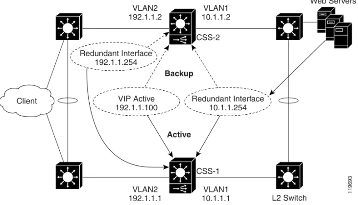
redundancy is with a virtual interface redundancy configuration where the master CSS processes all client requests to a VIP with a Web-server farm behind the CSSs and connected to the CSSs through a Layer 2 switch (Figure 1-1). If the master CSS becomes unavailable, the backup CSS becomes master and processes all client requests for the VIP.
Note The CSS does not support VIP redundancy and box-to-box redundancy configurations simultaneously. For information about box-to-box redundancy, refer to Chapter 3, Configuring Box-to-Box Redundancy.
Chapter 1 Configuring VIP and Virtual Interface Redundancy
Overview of VIP and Virtual Interface Redundancy
To set up CSSs for VIP redundancy, you must configure a virtual router (VR) on each CSS that will participate in the redundant configuration. A VR is an entity within a CSS with which you associate an existing VIP. A VIP becomes redundant when you associate it with a VR. You can configure a maximum of 255 VRs for each VLAN.
Note The VIP address must already exist in at least one active content rule or source group.
Figure 1-1 Example of VIP and Virtual Interface Redundancy
Virtual routers providing redundancy for a VIP address are considered a VR pair. Each VR pair has the same VR identifier (VRID) and runs on the same VLAN, but runs on a different CSS. Once the VRs are configured, the CSSs negotiate for mastership using Virtual Router Redundancy Protocol (VRRP). A VR in a redundant VIP configuration that is designated as:
• Master processes all client requests directed to the VIP
VLAN2 192.1.1.2
VLAN1 10.1.1.2 CSS-2
VLAN2 192.1.1.1
VLAN1 10.1.1.1 VIP Active
192.1.1.100
Redundant Interface 10.1.1.254
CSS-1
L2 Switch
Web Servers
Client
119693
Backup
Active
Redundant Interface 192.1.1.254
Chapter 1 Configuring VIP and Virtual Interface Redundancy Overview of VIP and Virtual Interface Redundancy
• Backup may be either a:
– Backup VR, which forwards all client requests directed to the VIP to the master CSS
– Shared backup VR, which processes all client requests it receives and does not forward requests for the VIP to the master CSS
A CSS designated as the master of a VIP automatically sends a gratuitous ARP for the VIP when the CSS becomes the master, either at startup or upon failover. This process enables the Layer 2 switch to learn where to forward packets that are directed to the VIP from clients. The CSS transmits one ARP request packet and one ARP reply packet for every gratuitious ARP invocation.
For an example of VIP and virtual interface redundancy, see Figure 1-1.
Virtual Interface Redundancy
Virtual interface redundancy is a form of IP address redundancy that applies only to IP interfaces (not VIPs). A typical interface IP address on a CSS defines the interface in use on a particular VLAN. In a virtual interface redundancy
configuration, the CSS designated as master maintains control over the redundant virtual interface. Each CSS will also have its own circuit IP address that you can use for Telnet, SNMP, or Cisco View Device Manager (CVDM) user interface. The typical use for virtual interface redundancy is with a VIP redundancy configuration in which:
• Web servers are positioned behind a Layer 2 switch
• CSSs with the redundant virtual interface are positioned in front of the Layer 2 switch
• The servers are configured with a default route (gateway) pointing to the redundant virtual interface IP address on the private side of the CSS
• Upstream routers use the IP address of the public-side redundant virtual interface as the next hop
You must configure VRs with the same VRIDs on the subnets that are common to both CSSs. Once you associate the new VRIDs with the redundant virtual interface IP addresses, the CSSs uses VRRP to negotiate mastership of the redundant virtual interfaces.
Chapter 1 Configuring VIP and Virtual Interface Redundancy
Overview of VIP and Virtual Interface Redundancy
A CSS designated as the master of a redundant virtual interface automatically sends out gratuitous ARPs for the redundant virtual interface’s IP address when the CSS becomes the master, either at startup or upon failover. This process enables a Layer 2 switch to learn where to forward packets that are directed to the redundant virtual interface from the servers or the clients and allows a server’s default route to always point to the CSS designated as the master of the redundant virtual interface. The CSS transmits one ARP request packet and one ARP reply packet for every gratuitious ARP invocation.
For an example of VIP and virtual interface redundancy, see Figure 1-1.
Note Virtual interface redundancy does not support a CSS configured as a shared
backup.
You can also configure virtual interface redundancy on the uplinks of the CSSs when the VIPs reside on a subnet different from that of the uplinks. In this case, you cannot configure VIP redundancy on the public side of the CSSs. You will need to configure static routes on the upstream routers pointing to the redundant virtual interface on the CSS as the router’s next hop gateway to the subnet where the VIPs reside.
Fate Sharing
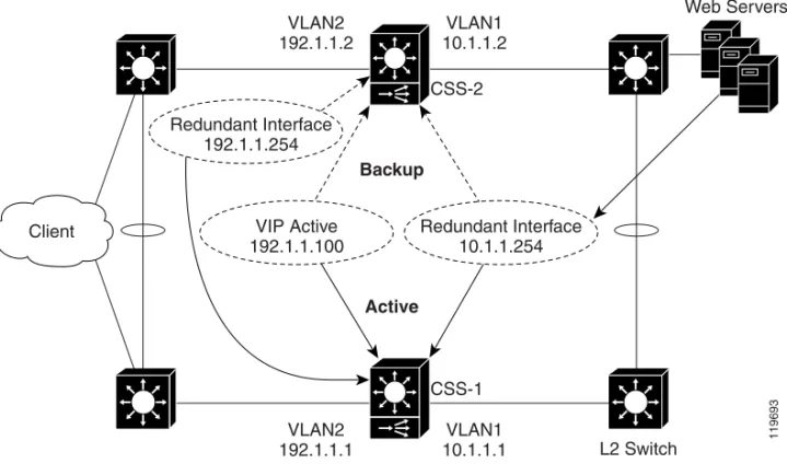
Fate sharing means that, when the redundant VIP fails over on the public side of the network from the master to the backup CSS, the redundant virtual interfaces on the public and the private sides of the network also fail over from the master to the backup CSS. If you do not configure virtual interface redundancy with VIP redundancy, asymmetric flows may result (Figure 1-2). Asymmetric flows occur when a CSS is master on the public side, but backup on the private side, which breaks the connection between the client and the server.
To ensure that the redundant VIP and the redundant virtual interfaces fail over at the same time, you must bind the front and the back instances of VRRP (the VRs) so that the same CSS processes both inbound and outbound flows. You
accomplish this by defining as critical services the IP addresses of the upstream router (the CSS default gateway) and the downstream Layer 2 switch that connects to the servers.
Chapter 1 Configuring VIP and Virtual Interface Redundancy Overview of VIP and Virtual Interface Redundancy
For example, the CSS provides a scripted keepalive (ap-kal-pinglist) that will check the health of the upstream router and the downstream Layer 2 switch. When you configure this keepalive, if either device fails, the critical service goes down and the redundant VIP and the redundant virtual interfaces fail over together to the backup CSS. For details on configuring critical services, see the “Configuring a Critical Service” section.
Figure 1-2 Example of Asymmetric Flows Without Fate Sharing
VLAN2 192.1.1.2
VLAN1 10.1.1.2 CSS-2
VLAN2 192.1.1.1
VLAN1 10.1.1.1 VIP Active
192.1.1.100
Redundant Interface 10.1.1.254
CSS-1 L2 Switch
Web Servers
Client
119694
Backup
Active
Active
Backup
Redundant Interface 192.1.1.254
Chapter 1 Configuring VIP and Virtual Interface Redundancy
Overview of VIP and Virtual Interface Redundancy
Examples of VIP and Virtual Interface Redundancy Configurations
The following sections provides examples of the most commonly used VIP and virtual interface redundancy configurations.
Active-Backup VIP and Virtual Interface Redundancy with Fate Sharing
Figure 1-3 shows an active-backup VIP and virtual interface redundancy configuration. CSS-1 is configured as the master for VIP address 192.1.1.100 and virtual interface address 10.1.1.254. If CSS-1 fails, CSS-2 (the backup CSS) will assume mastership of all flows destined to VIP address 192.1.1.100 and virtual interface address 10.1.1.254.
Figure 1-3 Example of Active-Backup VIP and Virtual Interface Redundancy
VLAN2 192.1.1.2
VLAN1 10.1.1.2 CSS-2
VLAN2 192.1.1.1
VLAN1 10.1.1.1 VIP Active
192.1.1.100
Redundant Interface 10.1.1.254
CSS-1
L2 Switch
Web Servers
Client
119693
Backup
Active
Redundant Interface 192.1.1.254
Chapter 1 Configuring VIP and Virtual Interface Redundancy Overview of VIP and Virtual Interface Redundancy
CSS-1 Configuration
circuit VLAN1
ip address 10.1.1.1 255.255.255.0
ip virtual-router 1 priority 101 preempt ip redundant-interface 1 10.1.1.254
ip critical-service 1 upstream_downstream
circuit VLAN2
ip address 192.1.1.1 255.255.255.0
ip virtual-router 2 priority 101 preempt ip redundant-vip 2 192.1.1.100
ip redundant-interface 2 192.1.1.254 ip critical-service 2 upstream_downstream
CSS-2 Configuration
circuit VLAN1
ip address 10.1.1.2 255.255.255.0 ip virtual-router 1 ip redundant-interface 1 10.1.1.254 ip critical-service 1 upstream_downstream
circuit VLAN2
ip address 192.1.1.2 255.255.255.0 ip virtual-router 2
ip redundant-vip 2 192.1.1.100 ip redundant-interface 2 192.1.1.254 ip critical-service 2 upstream_downstream
Chapter 1 Configuring VIP and Virtual Interface Redundancy
Overview of VIP and Virtual Interface Redundancy
Active-Active VIP and Virtual Interface Redundancy
A CSS can serve simultaneously as a master to one VR and as a backup to a different VR. This is called active-active VIP and virtual interface redundancy. All redundant VIP addresses will share the state of the VR to which they are associated. The same VR cannot be active on both CSSs simultaneously. Figure 1-4 shows an active-active VIP and virtual interface redundancy configuration with:
• CSS-1 configured as:
– VLAN1 IP address 10.1.1.1.
– VLAN2 IP address 192.1.1.1.
– Master VR for VIP address 192.1.1.100, virtual interface address 192.1.1.254, and virtual interface address 10.1.1.254.
– Backup VR for VIP address 192.1.1.101, virtual interface address 192.1.1.253, and virtual interface address 10.1.1.253. CSS-1 will forward all client requests it receives for VIP address 192.1.1.101 and virtual interface address 192.1.1. 253, and all server requests for virtual interface address 10.1.1.253 to CSS-2.
• CSS-2 configured as:
– VLAN1 IP address 10.1.1.2.
– VLAN2 IP address 192.1.1.2
– Master VR for VIP address 192.1.1.101, virtual interface address 192.1.1.253, and virtual interface address 10.1.1.253.
– Backup VR for VIP address 192.1.1.100, virtual interface address 192.1.1.254, and virtual interface address 10.1.1.254. CSS-2 will forward all client requests it receives for VIP address 192.1.1.100 and virtual interface address 192.1.1. 254, and all server requests for virtual interface address 10.1.1.254 to CSS-1.
Chapter 1 Configuring VIP and Virtual Interface Redundancy Overview of VIP and Virtual Interface Redundancy
Figure 1-4 Example of Active-Active VIP and Virtual Interface Redundancy
CSS-1 Configuration
circuit VLAN1
ip address 10.1.1.1 255.255.255.0 ip virtual-router 1 priority 101 preempt ip virtual-router 2
ip redundant-interface 1 10.1.1.254 ip redundant-interface 2 10.1.1.253 ip critical-service 1 upstream_downstream ip critical-service 2 upstream_downstream
Default Gateway 10.1.1.254 VLAN2
192.1.1.2
VLAN1 10.1.1.2
CSS-2
VLAN2 192.1.1.1
VLAN1 10.1.1.1 VIP Active
192.1.1.101 Redundant Interface10.1.1.253
CSS-1 L2 Switch
Default Gateway 10.1.1.253
Client
119695
Active Active
Active Active
Redundant Interface 192.1.1.253
Redundant Interface 192.1.1.254
VIP Active
Chapter 1 Configuring VIP and Virtual Interface Redundancy
Overview of VIP and Virtual Interface Redundancy
circuit VLAN2
ip address 192.1.1.1 255.255.255.0 ip virtual-router 3 priority 101 preempt ip virtual-router 4
ip redundant-vip 3 192.1.1.100 ip redundant-vip 4 192.1.1.101
ip redundant-interface 3 192.1.1.254 ip redundant-interface 4 192.1.1.253 ip critical-service 3 upstream_downstream ip critical-service 4 upstream_downstream
CSS-2 Configuration
circuit VLAN1
ip address 10.1.1.2 255.255.255.0 ip virtual-router 1
ip virtual-router 2 priority 101 preempt ip redundant-interface 1 10.1.1.254
ip redundant-interface 2 10.1.1.253 ip critical-service 1 upstream_downstream ip critical-service 2 upstream_downstream
circuit VLAN2
ip address 192.1.1.2 255.255.255.0 ip virtual-router 3
ip virtual-router 4 priority 101 preempt ip redundant-vip 3 192.1.1.100
ip redundant-vip 4 192.1.1.101 ip redundant-interface 3 192.1.1.254 ip redundant-interface 4 192.1.1.253 ip critical-service 3 upstream_downstream ip critical-service 4 upstream_downstream
Chapter 1 Configuring VIP and Virtual Interface Redundancy Overview of VIP and Virtual Interface Redundancy
Shared VIP Redundancy
In a shared VIP redundancy configuration, both the master and the backup VRs process flows destined to the same VIP. However, only the master VR (CSS-1) responds to ARP requests for the VIP address 192.1.1.100.
Note Shared VIP redundancy is not supported with VRID peering. See the “Configuring VRID Peering” section.
A shared VIP redundancy configuration has the following requirements:
• Direct uplink connections to routers (no common Layer 2 connection between CSSs)
• Direct connection between the CSSs to enable the backup CSS to forward ARP requests to the master CSS
• Mirrored content on the servers
• Direct connection from the servers to the CSSs eliminating the need for fate sharing
• Session- or flow-based (not packet-by-packet) ECMP router upstream to preserve flow state
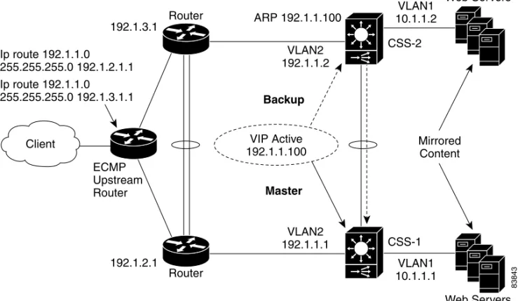
Figure 1-5 shows a shared VIP redundancy configuration with:
• CSS-1 configured as master VR for VIP address 192.1.1.100
• CSS-2 configured as shared backup for VIP address 192.1.1.100
Notice that CSS-2 (shared backup VR for VIP 192.1.1.100) forwards the ARP request for 192.1.1.100 to CSS-1 for a response.
Chapter 1 Configuring VIP and Virtual Interface Redundancy
Overview of VIP and Virtual Interface Redundancy
Figure 1-5 Example of Shared VIP Redundancy
CSS-1 Configuration
circuit VLAN1
ip address 10.1.1.1 255.255.255.0
circuit VLAN2
ip address 192.1.1.1 255.255.255.0 ip virtual-router 1
ip redundant-vip 1 192.1.1.100 shared
Web Servers 192.1.3.1
Router
Router 192.1.2.1
VLAN1 10.1.1.2 VLAN2
192.1.1.2
VLAN2 192.1.1.1
VLAN1 10.1.1.1 CSS-2
CSS-1 ARP 192.1.1.100
ECMP Upstream Router Ip route 192.1.1.0
255.255.255.0 192.1.2.1.1 Ip route 192.1.1.0
255.255.255.0 192.1.3.1.1
Mirrored Content
Web Servers
VIP Active 192.1.1.100 Client
83843
Backup
Chapter 1 Configuring VIP and Virtual Interface Redundancy VIP and Virtual Interface Redundancy Configuration Quick Start
CSS-2 Configuration
circuit VLAN1
ip address 10.1.1.2 255.255.255.0
circuit VLAN2
ip address 192.1.1.2 255.255.255.0 ip virtual-router 1
ip redundant-vip 1 192.1.1.100 shared
VIP and Virtual Interface Redundancy Configuration
Quick Start
Table 1-1 provides a quick overview of the steps required to configure
active-backup VIP and virtual interface redundancy with fate sharing for CSS-1. Each step includes the CLI command required to complete the task. For a complete description of each feature and all the options associated with the CLI command, see the sections following Table 1-1.
Table 1-1 VIP and Virtual Interface Redundancy Configuration Quick Start
Task and Command Example 1. Enter config mode.
# config (config)#
2. Enter service mode and configure a service to be used as a critical service or use an existing service.
(config)# service upstream_downstream
(config-service[upstream_downstream])# ip address 192.1.1.75 (config-service[upstream_downstream])# keepalive type script ap-kal-pinglist “191.1.1.20 10.1.1.20”
(config-service[upstream_downstream])# keepalive frequency 2 (config-service[upstream_downstream])# keepalive maxfailure 2 (config-service[upstream_downstream])# keepalive retryperiod 2 (config-service[upstream_downstream])# active
Chapter 1 Configuring VIP and Virtual Interface Redundancy
VIP and Virtual Interface Redundancy Configuration Quick Start
3. Enter circuit mode for VLAN1.
(config)# circuit VLAN1 (config-circuit[VLAN1])#
4. Configure a circuit IP address.
(config-circuit[VLAN1])# ip address 10.1.1.1/24 (config-circuit-ip[VLAN1-10.1.1.1])#
5. Configure the VR. If you do not have a preference as to which router becomes master, you may leave the default priority at 100. If you have a preference, assign a higher priority to one router using the priority option. When you want a VR to assume mastership in all circumstances, include the
preempt keyword.
(config-circuit-ip[VLAN1-10.1.1.1])# ip virtual-router 1 priority 101 preempt
6. Configure the redundant virtual interface.
(config-circuit-ip[VLAN1-10.1.1.1])# ip redundant-interface 1 10.1.1.254
7. Configure an existing service as a critical service for the VR.
(config-circuit-ip[VLAN1-10.1.1.1])# ip critical-service 1 upstream_downstream
8. Enter circuit mode for the next desired circuit VLAN.
(config)# circuit VLAN2 (config-circuit[VLAN2])#
9. Configure a circuit IP address.
(config-circuit[VLAN2])# ip address 192.1.1.1/24 (config-circuit-ip[VLAN2-192.1.1.1])#
10. Configure the VR.
(config-circuit-ip[VLAN2-192.1.1.1])# ip virtual-router 2 priority 101 preempt
11. Configure the redundant VIP on the VR.
(config-circuit-ip[VLAN2-192.1.1.1])# ip redundant-vip 2 192.1.1.100
Table 1-1 VIP and Virtual Interface Redundancy Configuration Quick Start (continued)
Chapter 1 Configuring VIP and Virtual Interface Redundancy VIP and Virtual Interface Redundancy Configuration Quick Start
You would configure CSS-2 in a similar manner, with the exception of the
priority and preempt options of the ip virtual-router command. The following running-config example shows the results of entering the commands listed in Table 1-1.
!************************* INTERFACE ************************* interface 2/1
bridge vlan 2
!************************** CIRCUIT ************************** circuit VLAN1
ip address 10.1.1.1 255.255.255.0
ip virtual-router 1 priority 101 preempt ip redundant-interface 1 10.1.1.254 ip critical-service 1 upstream_downstream
circuit VLAN2
ip address 192.1.1.1 255.255.255.0
ip virtual-router 2 priority 101 preempt ip redundant-vip 2 192.1.1.100
ip critical-service 2 upstream_downstream 12. Configure the redundant virtual interface on the VR.
(config-circuit-ip[VLAN2-192.1.1.1])# ip redundant-interface 2 192.1.1.254
13. Configure the critical service for the VR.
(config-circuit-ip[VLAN2-192.1.1.1])# ip critical-service 2 upstream_downstream
14. (Recommended) Verify the configuration.
(config)# show virtual-routers
Table 1-1 VIP and Virtual Interface Redundancy Configuration Quick Start (continued)
Chapter 1 Configuring VIP and Virtual Interface Redundancy
Configuring VIP and Virtual Interface Redundancy
!************************** SERVICE ************************** service upstream-downstream
ip address 192.1.1.10
keepalive type script ap-kal-pinglist “192.1.1.20 10.1.1.20" keepalive frequency 2
keepalive maxfailure 2 keepalive retryperiod 2 active
Configuring VIP and Virtual Interface Redundancy
You must configure each CSS that is part of a redundant configuration. The following sections describe how to configure VIP and virtual interface redundancy.
• Configuring a Circuit IP Interface
• Configuring a Virtual Router
• Configuring a Redundant VIP
• Configuring a Redundant Virtual Interface
• Configuring VRID Peering
• Configuring a Critical Service
• Configuring a Critical Physical Interface
• Synchronizing a VIP Redundancy Configuration
Configuring a Circuit IP Interface
Because this chapter is dedicated to configuring VIP and virtual interface redundancy, it contains only those circuit IP commands that pertain to this feature. For a complete description of all circuit IP commands, refer to the Cisco Content Services Switch Routing and Bridging Configuration Guide.
Before you can configure VIP and virtual interface redundancy, you must configure a circuit IP interface and assign it an IP address. To enter a specific circuit configuration mode, enter the circuit command and VLAN as shown in the following example:
(config)# circuit VLAN2 (config-circuit[VLAN2])#
Chapter 1 Configuring VIP and Virtual Interface Redundancy Configuring VIP and Virtual Interface Redundancy
Note When you use the circuit command, enter the word “VLAN” in uppercase letters and do not include a space between VLAN and the VLAN number (for example, VLAN1).
To assign an IP address to a circuit, use the ip address command from the specific circuit mode. Enter the IP address and a subnet mask in CIDR bitcount notation or dotted-decimal notation. The subnet mask range is /8 to /32. For example, to configure an IP address and subnet mask for VLAN1, enter:
(config-circuit[VLAN2])# ip address 192.1.1.1 /24
When you specify an IP address, the mode changes to the specific circuit-ip-VLAN-IP address as shown:
(config-circuit-ip[VLAN2-192.1.1.1])#
Configuring a Virtual Router
To create a virtual router (VR) on a CSS and configure the identifier and priority that is used when negotiating control of associated VIPs, use the ip virtual-router
command. You must configure the VR before you can configure redundant VIPs. A VR’s role as a master or backup is determined during negotiations between all VRs with the same VRID and residing on the same VLAN.
Note In a VRID peering or critical phy configuration, suspending a reporter that is configured as a critical reporter causes all VRs associated with it to go down, which causes a failover from master to backup. See the “Configuring VRID Peering” and the “Configuring a Critical Physical Interface” sections. The syntax and options for the IP interface command are:
ip virtual-router vrid {priority number}{preempt} The variables and options are:
• vrid - The virtual router identifier (VRID). Enter an integer between 1 and 255. You can configure 255 VRs per VLAN. Virtual routers are considered peers when they have the same VRID and reside in the same VLAN.
Chapter 1 Configuring VIP and Virtual Interface Redundancy
Configuring VIP and Virtual Interface Redundancy
• prioritynumber - The optional priority of the VR with respect to its peers. The default priority value is 100. Enter an integer between 1 and 255. A VR with the highest priority usually becomes master. However, a higher priority VR will not assume mastership from a lower priority master unless you include the preempt option.
When a VR is the master, it handles the traffic directed to its associated VIPs. To set a VR so that it will always be master, set its priority to 255 and configure it with the preempt option.
• preempt - The optional keyword that allows a higher priority VR to assert mastership over a lower priority VR. By default, a VR does not become master if the current master has a lower priority.
For example, if a CSS with a VR that has a low priority boots before other CSSs, that VR becomes the master. When another CSS with a VR that has a higher priority boots, it will not take the mastership from the first router unless you specify the preempt option on the higher priority VR. This option does not have an effect if the priority of the two VRs is identical. You can use this option with or without the priority option. You can configure only one VR as the master of a particular VIP.
Caution Never configure the preempt option on the same VR on both CSSs. Such a configuration may result in both CSSs becoming master, which will cause network problems.
Because a VR’s priority is dependent on the state of the critical services, the priority field status in the show virtual router display may be different than the priority you configured. The priority may be different when you:
• Assign a priority of 255 to a VR and that VR gains mastership, the CSS automatically reconfigures that VR’s priority to 254. This action ensures that you can assign a different VR a priority of 255.
• Configure critical services. The critical service types are:
– scripted - the priority changes to 0 when one service in the scripted group goes down.
– redundancy uplink - the priority changes to 0 when all of the services in the uplink group go down.
– local - the priority changes to 0 when all of the services in the local group go down. Local services include all services other than scripted and uplink.
Chapter 1 Configuring VIP and Virtual Interface Redundancy Configuring VIP and Virtual Interface Redundancy
For information about configuring critical services, see the “Configuring a Critical Service” section.
For example:
(config-circuit-ip[VLAN2-192.1.1.1])# ip virtual-router 2 priority 1 preempt
To remove the VR from the CSS, enter:
(config-circuit-ip[VLAN2-192.1.1.1])# no ip virtual-router 2
Configuring a Redundant VIP
To associate an existing VIP with a VR and, if required, configure the VR as a shared backup, use the ip redundant-vip command. A shared backup VR processes client requests. A redundant VIP configuration can consist of only two CSSs.
Note Before you use this command, the VIP must already be configured in at least one active content rule or source group. Additionally, if you defined the content rule or source group VIP using the range option, you must configure an identical range for the redundant VIP. For information about configuring VIPs in content rules and source groups, refer to the Cisco Content Services Switch Content
Load-Balancing Configuration Guide. The syntax of this IP mode command is:
ip redundant-vip vrid vip_address {range number} {shared} The variables and options are:
• vrid - The ID for an existing VR.
• vip_address - The address for the redundant VIP. This address must already be configured in at least one active content rule or source group. Enter an IP address in dotted-decimal notation (for example, 192.1.1.100).
• rangenumber - The optional keyword and variable if an IP address range is specified in the content rule or source group. You cannot specify a range that differs from the range in the content rule. Also, you cannot specify address ranges that overlap. Enter a number from 0 to 65535. The default is 1.
Chapter 1 Configuring VIP and Virtual Interface Redundancy
Configuring VIP and Virtual Interface Redundancy
• shared - The optional keyword to enable shared VIP redundancy. When you use this option, the master and backup VRs share the processing of traffic directed to the VIP, so the backup does not forward packets to the master. Configure each VIP identically on both CSSs.
Caution Do not connect Layer 2 devices between the CSSs and the routers in a shared VIP redundancy configuration. In addition, each router must be connected to only one CSS. Otherwise, all traffic will go to the master CSS, thus defeating the purpose of shared VIP redundancy.
For example:
(config-circuit-ip[VLAN2-192.1.1.1])# ip redundant-vip 2 192.1.1.100 range 10 shared
To remove a VIP from a VR, enter:
(config-circuit-ip[VLAN1-192.1.1.1])# no ip redundant-vip 1 192.1.1.100
Configuring a Redundant Virtual Interface
Servers use the IP address of a redundant virtual interface as a default gateway to guarantee that packets are sent to the CSS containing the master VR. To
accomplish this goal, configure a redundant virtual interface with the same VR as a redundant VIP that is configured in a rule that refers to the server. This configuration ensures that the master CSS for a VIP is the same CSS that is master for the redundant virtual interface. If the master CSS fails over to the backup CSS, both the VIP and the redundant interface fail over together. This configuration is called fate sharing. For details, see the “Fate Sharing” section.
We recommend that you also configure a redundant virtual interface on the public side of each CSS. This configuration provides a single IP address as the next hop for the upstream routers.
To configure a redundant virtual interface, use the ip redundant-interface
command.
The syntax of this IP mode command is: