T
ECHNICAL
October 1996R
EPORT
Source: ETSI TC-BTC Reference: DTR/BTC-02080
ICS: 35.120
Key words: Digital, PBX, transmission
Business TeleCommunications (BTC);
Comparison of PBX transmission requirements in standards
ANSI/TIA/EIA 464-B and ETS 300 439
ETSI
European Telecommunications Standards Institute ETSI Secretariat
Postal address: F-06921 Sophia Antipolis CEDEX - FRANCE
Office address: 650 Route des Lucioles - Sophia Antipolis - Valbonne - FRANCE X.400: c=fr, a=atlas, p=etsi, s=secretariat - Internet: [email protected]
Tel.: +33 4 92 94 42 00 - Fax: +33 4 93 65 47 16
Copyright Notification: No part may be reproduced except as authorized by written permission. The copyright and the
foregoing restriction extend to reproduction in all media.
Whilst every care has been taken in the preparation and publication of this document, errors in content, typographical or otherwise, may occur. If you have comments concerning its accuracy, please write to "ETSI Editing and Committee Support Dept." at the address shown on the title page.
Contents
Foreword ...5 Introduction ...5 1 Scope ...7 2 References ...7 3 Abbreviations...8 4 Reference Model ...9 5 Requirements ...105.1 Loss and loss - related parameters ...10
5.1.1 Port to port insertion loss...10
5.1.1.1 Insertion loss ranges ...12
5.1.1.2 Loss variations...12
5.1.1.3 Digital pad disabling...13
5.1.2 Frequency response...13
5.1.2.1 Comparison of both definitions of Frequency Response...13
5.1.2.2 2w - 2w ...14 5.1.2.3 2w - 4w ...14 5.1.2.4 4w - 4w ...15 5.1.2.5 2w - digital...15 5.1.2.6 4w - digital...17 5.1.3 Levels ...18
5.1.3.1 Comparison of both definitions of Interface Levels ...18
5.1.3.2 Interface levels...19
5.1.3.3 Level tracking: Tracking error ...21
5.1.3.4 Overload ...22
5.1.3.5 Level tracking: Overload compression ...23
5.1.3.6 Signal levels...24
5.1.4 Hybrid balance...25
5.1.5 Input Impedance...26
5.1.6 Echo loss...27
5.1.7 Stability loss...27
5.2 Voice impairment parameters...28
5.2.1 Noise ...28
5.2.1.1 Weighted noise...28
5.2.1.2 3 kHz flat noise ...28
5.2.1.3 Single frequency noise ...29
5.2.1.4 Spurious out of band signals ...29
5.2.2 Balance ...30
5.2.2.1 Longitudinal to metallic balance...30
5.2.2.2 Transverse balance ...31
5.2.3 Crosstalk ...32
5.2.4 Distortion ...33
5.2.4.1 Quantization distortion ...33
5.2.4.2 Single frequency distortion ...34
5.2.5 Delay ...34
5.2.5.1 Echo path delay ...34
5.3 Loudness levels ...35
5.3.1 Acoustic reference level plan ...37
5.3.1.1 ARLP Background ...37
5.3.1.2 Acoustic Reference Level Plan Description...37
5.3.1.3 ARLP Loss Design Application for System-Specific Telephones ...38
5.4 Other impairment parameters ... 39
5.4.1 Inter-modulation distortion ... 39
5.4.2 Group delay distortion... 40
5.4.3 Impulsive noise ... 40 5.4.4 Jitter ... 41 5.4.5 Gain hit ... 41 5.4.6 Phase hit ... 41 5.4.7 Drop out ... 42 History ... 43
Foreword
This ETSI Technical Report (ETR) has been produced by the Technical Committee (TC) Business TeleCommunications (BTC) of the European Telecommunications Standards Institute (ETSI).
This ETR is a Telecommunications Systems Bulletin (TSB), jointly produced by:
- Telecommunications Industry Association (TIA) Subcommittee TR-41.1, MultiLine Telecommunications Systems (MLTS), and
- ETSI TC BTC.
The document is being published as a TIA TSB and as an ETR. The document is not an industry standard and compliance to its contents is not mandatory. The document compares corresponding Private Branch eXchange (PBX) transmission requirements in TIA and ETSI standards to be considered when developing equipment or standards intended for global application.
ETSI has granted TIA permission to use copyrighted material from ETS 300 439, "Business TeleCommunications (BTC); Transmission characteristics of digital Private Branch eXchanges (PBXs)", in the TIA TSB. Likewise, TIA has granted ETSI permission to use copyrighted material from ANSI/TIA/EIA-464B-1996, "Requirements for Private Branch eXchange (PBX) Switching Equipment" in this ETR.
Introduction
Over the last decade, continuing telecommunications improvements have brought the continents closer together - digital signalling allows calls to be established in less than a second and digital transmission has improved voice quality. Such changes have made it convenient to call anywhere in the world without a thought being given to past difficulties in completing such calls with acceptable transmission quality. These improvements have made it possible for multi-national companies to efficiently conduct business in a real-time environment and to be able to efficiently design and produce world-wide products. This gives impetus to international telecommunications equipment suppliers and users of such equipment to consider the differences in transmission requirements of PBX systems that are manufactured for different world marketplaces.
This ETR provides a comparison of North American and European PBX standards with the goal of creating maximum commonality for serving the global PBX marketplace, while recognizing the existence of differences in regional telecommunications environments, regulatory practices, geographic constraints, and customer expectations. Technical differences between the TIA and PBX standards are identified and rationalized. This ETR can be considered a first step for eventual harmonization on a global basis.
1
Scope
This ETSI Technical Report (ETR) compares, in an orderly manner, like transmission requirements in ANSI/TIA/EIA-464B-1996, "Requirements for Private Branch eXchange (PBX) Switching Equipment" and those in ETS 300 439, "Business TeleCommunications (BTC); Transmission characteristics of digital Private Branch eXchanges (PBXs)".
Since only the PBX transmission requirements in TIA-464B and ETS 300 439 are compared, it is necessary to examine relevant portions of the scope of each of these standards to gain an overall idea of the scope of the comparison. ETS 300 439 provides transmission requirements while ANSI/TIA/EIA-464 provides transmission requirements as well as other PBX parameters, e.g., signalling and supervision. The following table is an overview comparison of the two documents.
TIA-464B ETS 300 439
SCOPE Digital PBX Digital PBX with Test Point
TRAFFIC 3,1 kHz voice 3,1 kHz voice
CODING (at interface to network)
mu-law A-law
Measurement Port-to-Port (full-channel) Port-to-test point (half-channel) INCLUDES (interfaces): Analogue Digital Cordless Loud-speaking (hands-free) Proprietary sets Yes Yes No No Yes Yes Yes
No (Planned for subsequent issue) No Yes Non-transmission requirements Yes No
Test methods for compliance No Yes
2
References
For the purposes of this ETR, the following references apply:
[1] ITU-T Recommendation G.122 (1993): "Influence of national systems on stability and talker echo in international connections".
[2] ITU-T Recommendation G.711 (1988): "Pulse code modulation (PCM) of voice frequencies".
[3] ITU-T Recommendation G.712 (1992): "Transmission performance
characteristics of pulse code modulation".
[4] ITU-T Recommendation O.41 (1994): "Psophometer for use on telephone -type circuits".
[5] ITU-T Recommendation Q.517 (1984): "Digital local and combined exchanges, Transmission characteristics".
[6] ITU-T Recommendation Q.551 (1994) : "Transmission characteristics of digital exchanges".
3
Abbreviations
For the purposes of this ETR, the following abbreviations apply:
A/TO Analogue trunk interface to analogue toll office (TO) trunk
A/TT Analogue trunk interface to tie trunk
AAL(A) Analogue trunk interface to analogue PSTN access line AAL(D) Digital trunk interface to analogue PSTN access line DAL Digital trunk interface to digital PSTN access line
DID Direct In Dialling
DISA Direct Inward System Access
ICS Digital line interface to ISDN Compatible Station
ISD/TT Digital trunk interface to integrated services trunk and digital interface to non ISDN digital or combination tie trunk
ISPBX Integrated services private branch exchange IST Digital trunk interface to integrated services trunk
K2 Analogue 2-wire trunk interface to analogue PSTN access line KD Digital trunk interface to digital PSTN access line
L2 Analogue 2-wire extension interface
LD Digital line interface to ISDN Compatible Station
M2 Analogue 2-wire tie-line interface
M4 Analogue 4-wire tie-line interface
MD Digital tie-line interface
ONS Line interface to on-premises station
OPS Line interface to off-premises station
S/ATT Analogue trunk interface to analogue satellite PBX tie trunk S/DTT Digital trunk interface to digital satellite PBX tie trunk
4
Reference Model
Each of the documents in this comparison specifies the interfaces to which the PBX can connect and make connections between. An understanding of these interfaces is integral to the proper interpretation and application of the transmission requirements being compared.
Figure 1, Representative PBX Network Connections, presents a simplified model of the PBX interfaces in terms of the ETSI interface designations. The correspondence to TIA interface designations is shown in the figure. Note that there is no ETSI designation for an Off-Premise Station interface; thus the TIA designation is used for that interface.
Analogue Local exchange Office Digital Local exchange Office Digital PBX Tandem, Main or Satellite Digital Inter-exchange Office Analogue Inter-exchange Office Analogue PBX Tandem, Main or Satellite Digital PBX CB CB CB CB TE TE TE K2 KD KD K2 KD = DAL or AAL (D) K2 = AAL or A/TO LD = ICS L2 = ONS MD = ISD/TT or IST M2 = A/TT M4 = A/TT K2 KD KD K2 M2 M2 M4 M4 MD MD OPS L2 LD
Note: Interfaces are represented by: Analogue 2-wire interface Analogue 4-wire interface Digital interface
Channel Bank
5
Requirements
On the following pages, the corresponding requirements in each document are referenced and then compared side-by-side. This is followed by an analysis of the comparison where applicable. Additional sheets provide tables, figures, and background explanation for specific requirements.
5.1 Loss and loss - related parameters 5.1.1 Port to port insertion loss
TIA - 464B ETS 300 439
5.2.1 Insertion loss criteria for ISPBX 5.2.4 ISPBX loss ranges
Tables 12, 13 ISPBX loss plan
3.1.4 Transmission loss
5.2.1 Nominal transmission loss (analogue interfaces)
6.2 Nominal transmission loss (digital interfaces) 8.2 Transmission loss between interfaces Annex A, subclause A.4.2, Measurements The insertion loss is specified as port-to-port loss
between PBX interfaces and Loss Ranges. Requirements are formatted in a loss plan matrix; each matrix cell defines the nominal insertion loss in dB for both directions of transmission. Attached table 1 gives the loss for connections involving lines and private network trunks; table 2 gives the loss for connections between access lines to the PSTN.
Conditions:
Measured at 1 004 Hz (nominal) with both source and measuring instruments at 600 Ω impedance.
Nominal transmission Loss NL is defined as the difference between relative input level Li of one port and the relative output level Lo of the other port in a connection, including the loss SL of an digital gain-or loss- pad.
NL = Li - Lo + SL
where Li and Lo are in dBr referenced to 0 dBr. The values for Li and Lo must be stated by the supplier. Annexes E1 through E4 provide - for information only - values used earlier in different countries. Conditions:
Measured at 1 020 Hz (nominal) with a test level of -10 dBm0 (annex A, subclause A. 4.2).
Analysis: In TIA, the port-to-port-loss is specified, but the allocation of loss between input and output ports is left to the manufacturer's discretion. In ETSI, neither the port-to-port loss nor the allocation of loss is specified. However, the port-to-port-loss must be stated by the supplier on the basis of input/output levels. These losses are in many cases subject to national requirements, which differ from country to country on the signal levels at the point of connection to the PSTN while maintaining a harmonized requirement at the point of connection to the ISDN. To address PBX features such as forwarding of inward dial calls (DID) and external access to corporate networks (DISA), TIA specifies a loss plan between access lines. No comparable plan exists in the ETSI standards.
Table 1: TIA-464B Loss Plan for Lines and Private Network Trunks
ONS OPS ICS A/TT DAL ISD/TT S/ATT S/DTT
& IST ↑ ↓ ↑ ↓ ↑ ↓ ↑ ↓ ↑ ↓ ↑ ↓ ↑ ↓ ↑ ↓ → 6 3 3 3 3 3 3 3 ONS
←
6 3 6 3 6 9 3 3 → 3 0 -3 2 3 0 2 2 OPS←
3 0 0 2 6 6 2 2 → 6 0 0 0 0 0 0 0 ICS←
3 -3 0 -3 0 0 -3 -3 → 3 2 -3 0 0 -3 0 0 A/TT←
3 2 0 0 3 3 0 0 → 6 6 0 3 0 0 6 6 DAL & IST←
3 3 0 0 0 0 0 0 → 9 6 0 3 0 0 6 6 ISD/TT←
3 0 0 -3 0 0 0 0 → 3 2 -3 0 0 0 0 0 S/ATT←
3 2 0 0 6 6 0 0 → 3 2 -3 0 0 0 0 0 S/DTT←
3 2 0 0 6 6 0 0 → 0 0 -6 0/2 -3 -3/0 0 0 AAL(A)←
0 0 -3 0/2 3 3/6 0 0 → 3 0 -3 2 0 0/-3 0 0 AAL(D) * Note←
3 0 0 2 3 6/3 0 0 → 6 3 0 0 -3 -3 3 3 A/TO←
6 3 3 0 3 3 3 3 (Values in dB)NOTE: IST connections only, not DAL
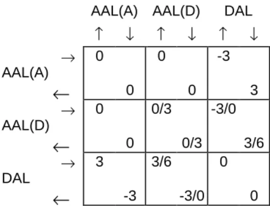
Table 2: TIA-464B Loss Plan for Inter-Access Line Connections AAL(A) AAL(D) DAL
↑ ↓ ↑ ↓ ↑ ↓ → 0 0 -3 AAL(A)
←
0 0 3 → 0 0/3 -3/0 AAL(D)←
0 0/3 3/6 → 3 3/6 0 DAL←
-3 -3/0 05.1.1.1 Insertion loss ranges
TIA - 464B ETS 300 439
5.2.4 ISPBX Loss Ranges Requirements not given
Station to Station
ONS-ONS: 4,5 dB to 7,5 dB ONS-OPS: 2,0 dB to 4,0 dB OPS-OPS: 0,0 dB to 0,5 dB Station to Trunk
Average loss between nominal and nominal plus 0,5 dB
Trunk to Trunk
Average loss between nominal and nominal plus 0,5 dB
Analysis: The TIA desired nominal values are shown in table 1, however a PBX may have a declared nominal value within the TIA range quoted above. The tolerance in subclause 5.1.2.1 is applied to the declared nominal value. In ETSI, consequently those loss 'ranges are not given, since the loss is left to the manufacturer's discretion or subject to national requirements. For loss variations in ETSI see subclause 5.1.1.2.
5.1.1.2 Loss variations
TIA - 464B ETS 300 439
5.2.5 Loss Variation 5.2.1 Nominal Transmission Loss (all analogue
interfaces)
6.2 Nominal Transmission Loss (all digital interfaces) Station-Station Mandatory: ±1,0 dB Desirable: ±0,3 dB Station-Trunk Mandatory: ±0,7 dB Desirable: ±0,4 dB Trunk-Trunk Mandatory: ±0,7 dB Desirable: ±0,4 dB Conditions:
To be met on 95 % of connections in each category. ONS-ONS, ONS-OPS, OPS-OPS connections treated as separate categories.
Loss variation is the difference between actual measured andthe nominal input/output
transmission loss as stated by the supplier. This differencecan be interpreted as the permitted tolerancedue to design tolerances, cabling and adjustment increments. The values shall lie in the range:
- 0,35 to +0,35 dB for analogue interfaces - 0,15 to +0,15 dB for digital interfaces
Conditions:
The values are referred to input- or output Half-Connections Losses only and not to Port-to-Port connections.
Analysis: Combining ETSI input and output tolerances, the path tolerance requirements for station-station are equivalent; the TIA requirements are tighter for station-station-trunk and trunk-trunk. However, depending on allocation between input and output ports, meeting TIA connection requirements does not guarantee meeting ETSI half-channel requirements.
5.1.1.3 Digital pad disabling
TIA - 464B ETS 300 439
5.2.6 Digital Pad Disabling 3.1.7.1 Bit Integrity
4 Compliance Principles
Digital pads for loss implementation shall be disabled on digital data calls
Digital processing devices must be disabled to provide bit integrity when needed. If digital pads are part of the loss adjustment of input- and output half channels, they must be rendered inoperative during all transmission measurements, with the exception of the parameters Nominal Transmission Loss and Loss Tolerances.
Analysis: There is no issue in TIA-464B about the influence of digital pads on transmission parameters such as level tracking, quantizing distortion, output level, overload compression etc. With respect to the above mentioned parameters, the ETSI Standard is mainly based on ITU-T G.712 [3] Recommendations, which provides parameter limits, assuming no digital loss or gain pads. To avoid the calculation and creation of new, extended limits for the standard, all digital signal processing devices including digital pads should be switched inoperative. This procedure was agreed upon since, usually, the influence on transmission quality of those devices is known and can be tolerated in practice.
5.1.2 Frequency response
5.1.2.1 Comparison of both definitions of Frequency Response
In both standards, the frequency response is defined as the difference between the actual loss at any frequency and the actual loss at the reference frequency 1 004 Hz (TIA) or 1 020 Hz (ETSI). With respect to the given frequency masks, positive values indicate more loss and vice versa. The loss at the reference frequency is assumed to be 0 dB.
By definition, loss is the logarithmic ratio between two values of power. For TIA-464B requirements, measurements of frequency response are performed with all analog ports terminated with 600 ( (section 5.2 of TIA-464B). Since this termination is independent of frequency, the measured voltage response across the port interface is identical with the power response. In contrast, for ETSI requirements, the ports are terminated with their nominal impedance, which is capacitive complex. i.e., frequency-dependent. Therefore, ETSI defines the frequency response Loss Distortion with Frequency, (subclause 3.1.5 of ETS 300 439) as the logarithmic ratio between the actual measured voltage at the reference frequency (1 020 Hz) and the voltage at any other frequency. This definition is in accordance with ITU-T Recommendations Q.551, section 1.2.5 [6].
5.1.2.2 2w - 2w
TIA - 464B ETS 300 439
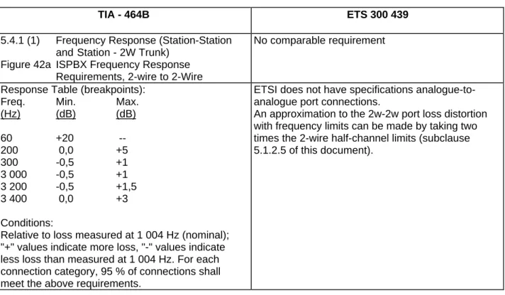
5.4.1 (1) Frequency Response (Station-Station andStation - 2W Trunk)
Figure 42a ISPBX Frequency Response Requirements, 2-wire to 2-Wire
No comparable requirement
Response Table (breakpoints):
Freq. Min. Max.
(Hz) (dB) (dB) 60 +20 --200 0,0 +5 300 -0,5 +1 3 000 -0,5 +1 3 200 -0,5 +1,5 3 400 0,0 +3 Conditions:
Relative to loss measured at 1 004 Hz (nominal); "+" values indicate more loss, "-" values indicate less loss than measured at 1 004 Hz. For each connection category, 95 % of connections shall meet the above requirements.
ETSI does not have specifications analogue-to-analogue port connections.
An approximation to the 2w-2w port loss distortion with frequency limits can be made by taking two times the 2-wire half-channel limits (subclause 5.1.2.5 of this document).
Analysis: Comparing the TIA template to the approximation for ETSI suggested above, TIA is more stringent than ETSI, except for the maximum relative loss in the range of 600 Hz to 2 400 Hz. 5.1.2.3 2w - 4w
TIA - 464B ETS 300 439
5.4.1 (2) Frequency Response (Station-4W Trunk and 2W Trunk - 4W Trunk)
Figure 42b ISPBX Frequency Response. Requirements, 2-wire to 4-Wire
No comparable requirement
Response Table (breakpoints):
Freq. Min. Max.
(Hz) (dB) (dB) 60 +20 * --200 0,0 +4 300 -0,4 +0,65 3 000 -0,4 +0,65 3 200 -0,4 +1,5 3 400 0,0 +3 * in 4w-2w direction: +16 dB Conditions:
Relative to loss measured at 1 004 Hz (nominal); "+" values indicate more loss, "-" values indicate less loss than measured at 1 004 Hz. For each connection category, 95 % of connections shall meet the above requirements.
ETSI does not have specifications for analogue-to-analogue port connections.
An approximation to the 2w-4w port loss distortion with frequency limits can be made by summing the 2-wire and 4-wire half-channel limits (subclauses 5.1.2.5 and 5.1.2.6 of this document).
Analysis: Comparing the TIA template to the approximation for ETSI suggested above, TIA is more stringent than ETSI except for the maximum relative loss in the ranges of 600 to 2 000 Hz and approximately 3 350 to 3 400 Hz.
5.1.2.4 4w - 4w
TIA - 464B ETS 300 439
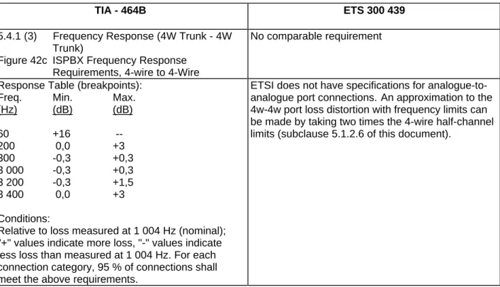
5.4.1 (3) Frequency Response (4W Trunk - 4W Trunk)
Figure 42c ISPBX Frequency Response Requirements, 4-wire to 4-Wire
No comparable requirement
Response Table (breakpoints):
Freq. Min. Max.
(Hz) (dB) (dB) 60 +16 --200 0,0 +3 300 -0,3 +0,3 3 000 -0,3 +0,3 3 200 -0,3 +1,5 3 400 0,0 +3 Conditions:
Relative to loss measured at 1 004 Hz (nominal); "+" values indicate more loss, "-" values indicate less loss than measured at 1 004 Hz. For each connection category, 95 % of connections shall meet the above requirements.
ETSI does not have specifications for analogue-to-analogue port connections.An approximation to the 4w-4w port loss distortion with frequency limits can be made by taking two times the 4-wire half-channel limits (subclause 5.1.2.6 of this document).
Analysis: Comparing the TIA template to the approximation for ETSI suggested above, TIA is more stringent than ETSI, except for the maximum relative loss in the range of approximately 3 300 to 3 400 Hz.
5.1.2.5 2w - digital
TIA - 464B ETS 300 439
5.4.1 (4) Frequency Response (Station-Digital and 2W Trunk - Digital)
Figure 42d ISPBX Frequency Response Requirements, 2-wire to Digital
3.1.5 Definition of Loss Distortion 5.2.3 Variation of gain with frequency
(analogue half connections)
Figures 6, 7 Loss Distortion with frequency (input and output connections)
Template: Figure 2
Response Table (breakpoints):
Freq. Min. Max.
(Hz) (dB) (dB) 60 +20 --200 0,0 +3 * 300 -0,25 +0,5 3 000 -0,25 +0,5 3 200 -0,25 +0,75 3 400 0,0 +1,5
* For analog-to-digital conversion. The max. value at 200 Hz is +2 dB for digital-to-analog conversion Conditions:
Relative to loss measured at 1 004 Hz (nominal); "+" values indicate more loss, "-" values indicate less loss than measured at 1 004 Hz. For each connection category, 95 % of connections shall meet the above requirements.
K2, L2, M2, K4, and M4 Interfaces: Template: Figure 2
Freq. Min. Max.
(Hz) (dB) (dB)* inp outp <200 0 -0,3 --200 300 -0,3 -0,3 --300 400 -0,3 -0,3 +1 400 600 -0,3 -0,3 +0,75 600 2 000 -0,3 -0,3 +0,35 2 000 2 400 -0,3 -0,3 +0,45 2 400 3 000 -0,3 -0,3 +0,7 3 000 3 400 -0,3 -0,3 +1,7 3 400 3 600 -0,3 -0,3 -->3 600 0 0
--* same for input and output
Conditions: Referenced to 1 020 Hz. Preferred input level: -10 dBm0.
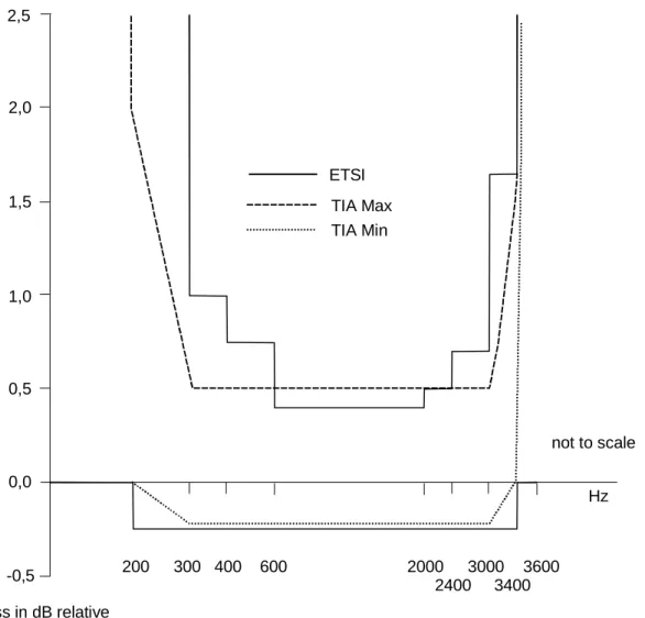
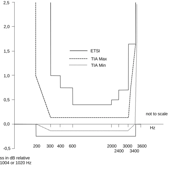
Analysis: TIA requirements are tighter than ETSI with the exception of maximum loss relative to 1 004 Hz in the frequency range 600-2 400 Hz. Though not shown in the template, TIA requirements extend beyond 4 000 Hz with minimum loss, relative to 1 004 Hz, of 28 (D-A) or 32 (A-D) dB at 4 600 Hz and beyond. In ETSI, requirements for the frequency response are only related to the speech band from 200 - 3 600 Hz. Signals above 3,6 kHz, which may cause interference (harm) to the public network are considered as "Access Requirements", and contained in TBRs. For additional information see also "Comparison of both definitions of Frequency Response" in subclause 5.1.2 of this document.
-0,5 0,0 0,5 1,0 1,5 2,0 2,5 not to scale 200 300 400 600 2000 2400 3000 3400 3600 Hz Loss in dB relative to 1004 or 1020 Hz ETSI TIA Min TIA Max
5.1.2.6 4w - digital
TIA - 464B ETS 300 439
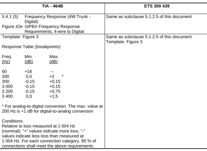
5.4.1 (5) Frequency Response (4W Trunk - Digital)
Figure 42e ISPBX Frequency Response Requirements, 4-wire to Digital
Same as subclause 5.1.2.5 of this document
Template: Figure 3
Response Table (breakpoints):
Freq. Min. Max.
(Hz) (dB) (dB) 60 +16 --200 0,0 +2 * 300 -0,15 +0,15 3 000 -0,15 +0,15 3 200 -0,15 +0,75 3 400 0,0 +1,5
* For analog-to-digital conversion. The max. value at 200 Hz is +1 dB for digital-to-analog conversion Conditions:
Relative to loss measured at 1 004 Hz (nominal); "+" values indicate more loss, "-" values indicate less loss than measured at 1 004 Hz. For each connection category, 95 % of connections shall meet the above requirements.
Same as subclause 5.1.2.5 of this document Template: Figure 3
Analysis: TIA requirements are tighter than ETSI with the exception of maximum loss relative to 1 004 Hz in the approximate frequency range 3 300-3 400 Hz.
Though not shown in the template, TIA requirements extend beyond 4 000 Hz with minimum loss, relative to 1 004 Hz, of 28 (D-A) or 32 (A-D) dB at 4 600 Hz and beyond.
For additional information see also "Comparison of both definitions of Frequency Response" in subclause 5.1.2.1 of this document.
-0,5 0,0 0,5 1,0 1,5 2,0 2,5 not to scale 200 300 400 600 2000 2400 3000 3400 3600 Hz Loss in dB relative to 1004 or 1020 Hz ETSI TIA Min TIA Max
Figure 3: 4-wire to digital frequency response 5.1.3 Levels
5.1.3.1 Comparison of both definitions of Interface Levels
The understanding and use of interface levels differs between TIA and ETSI standards. The main purpose of output interface levels in TIA-464B is to provide a reference point for other requirements and their measurement (TIA-464B section 5.1.4.3). The output level OL is referred to 0 dBm (TIA-464B section 5.3.1.1) and furthermore corresponds to the Digital MilliWatt DMW as defined in TIA-464B section 5.3.1.2 and based on ITU-T Recommendation G.711 [2] section 5. If a port is designated to have an OL of 0 dB, the meaning is, that a Standard Digital MilliWatt signal internal to the PABX results in an output analogue sine wave signal with a power of 1 mW (TIA-464B section 5.3.1.3). The Overload requirements in subclause 5.4.2 of ETS 300 439 must be considered here as well. Overload should occur for a sine wave signal whose average power is greater than +3,17 dBm at a 0 dB interface.
Combining these issues the definition of interface level in TIA can be expressed as follows:
The output level at an interface is designated 0 dB, if an internal digital signal, corresponding to the Digital MilliWatt, is resulting in a power of 1 mW at the terminating impedance of 600 Ω. Overload occurs at a level which, for mu-law coding, is +3,17 dB above the Digital MilliWatt for mu-law coding.
In ETSI, interface levels are expressed with the term "Relative Level". The values are given as relative input level Li and relative output level Lo at each analogue or digital interface. The purpose of this parameter must be seen in several ways. Primarily the relative level is directly related to the nominal loss NL of an input or output connection, which is defined as an unidirectional path between the interface and the Test Point. These relations are:
NLi = Li NLo = - Lo
Relative levels are used also in network planning in different applications. The relative output level at an interface may give an indication about the absolute signal power at this point, sincesignal levels are often expressed as a value in dBm0 (e.g. - 15 dBm0 for test signals) which is understood as the absolute signal power at a 0 dBr point. The relative input level is used to control an overloading during encoding by signal sources in practical use. The relative levels are defined at a frequency of 1 020 Hz and corresponding to the Digital MilliWatt and an analogue signal power of 1 mW as in TIA and based on ITU Recommendation G.711 [2].
The definition of a relative level in ETSI is referred to a termination with a frequency-dependant complex impedance. The nominal value of those impedances at the reference frequency 1 020 Hz may differ from 600 Ω, therefore the reference voltage is not necessarily 0,775 V. The definition can be given as follows:
The output level at an interface is designated 0 dBr, if an internal digital signal, corresponding to the Digital MilliWatt, is resulting in an analogue signal of 1 020 Hz with an apparent power of 1 mW at the terminating complex impedance. Overload occurs at a level which, for A-law coding, is + 3,14 dB above 1 mW (ITU-T Recommendation G.711 [2]). The definition of relative input levels is similar.
More detailed information about the concept and use of relative levels is given in the annexes C and D of ETS 300 439.
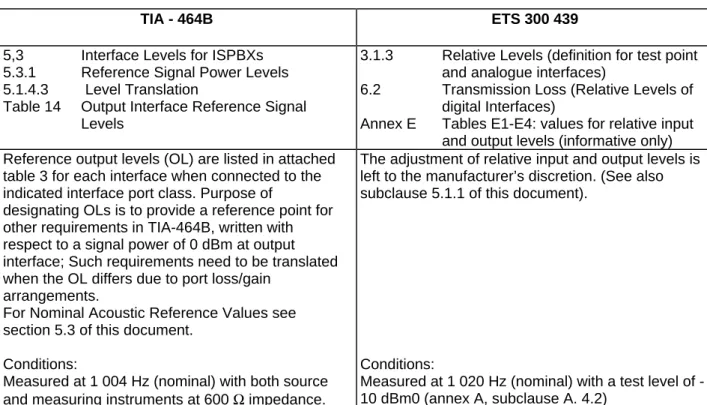
5.1.3.2 Interface levels
TIA - 464B ETS 300 439
5,3 Interface Levels for ISPBXs 5.3.1 Reference Signal Power Levels 5.1.4.3 Level Translation
Table 14 Output Interface Reference Signal Levels
3.1.3 Relative Levels (definition for test point and analogue interfaces)
6.2 Transmission Loss (Relative Levels of digital Interfaces)
Annex E Tables E1-E4: values for relative input and output levels (informative only) Reference output levels (OL) are listed in attached
table 3 for each interface when connected to the indicated interface port class. Purpose of
designating OLs is to provide a reference point for other requirements in TIA-464B, written with respect to a signal power of 0 dBm at output interface; Such requirements need to be translated when the OL differs due to port loss/gain
arrangements.
For Nominal Acoustic Reference Values see section 5.3 of this document.
Conditions:
Measured at 1 004 Hz (nominal) with both source and measuring instruments at 600 Ω impedance.
The adjustment of relative input and output levels is left to the manufacturer’s discretion. (See also subclause 5.1.1 of this document).
Conditions:
Measured at 1 020 Hz (nominal) with a test level of -10 dBm0 (annex A, subclause A. 4.2)
Analysis: The TIA output levels (there is no table for input levels) do, to some extent correspond to the Lo values in ETSI but with two important differences.
1) For any specific interface, they are, in most instances, a function of the port to which connected.
2) These levels are not prescribed as PBX functional requirements; their purpose is to be reference values for testing.
For additional information see also "Comparison of both definitions of interface levels" in subclause 5.1.3.1 of this document.
Table 3: TIA-464B Table Of Output Levels Interface Port
Class
Connected to Interface Port Class Output Level (OL) (dB)
ONS All other ports -3
OPS All other ports 0
ICS ONS, ICS 0
ICS OPS +3
ICS A/TT +3
ICS IST, ISD/TT 0
ICS S/ATT, S/DTT +3
ICS AAL(A) +3
ICS AAL(D), A/TO 0
A/TT ONS 0
A/TT OPS -2
A/TT Any tie trunk 0
A/TT AAL(A) 0 (note 2)
A/TT AAL(D0) -2
A/TT A/TO 0
IST ONS, ICS 0
IST OPS -3
IST Any tie trunk 0
IST AAL(A), AAL(D) 0
IST A/TO +3
ISD/TT ONS, OPS 0
ISD/TT A/TT +3
ISD/TT Any tie trunk except A/TT 0
ISD/TT AAL(A) +3 (note 2)
ISD/TT A/TO +3
ISD/TT AAL(D) 0
S/ATT, S/DTT OPS -2
S/ATT, S/DTT All other ports 0
AAL(A) (note 1) ONS +3
AAL(A) All other ports 0
AAL(D) Any port 0
A/TO ONS, OPS -3
A/TO A/TT, ISD/TT 0
A/TO S/ATT S/DTT -3
NOTE 1: ONS-AAL(A) connections shall have zero loss. To realize zero loss, the ports at each interface must be at the same level. To accomplish this, either the ONS-AAL(A) connection must shift to zero OL or the AAL(A) interface levels must change for ONS vs OPS connections as shown here.
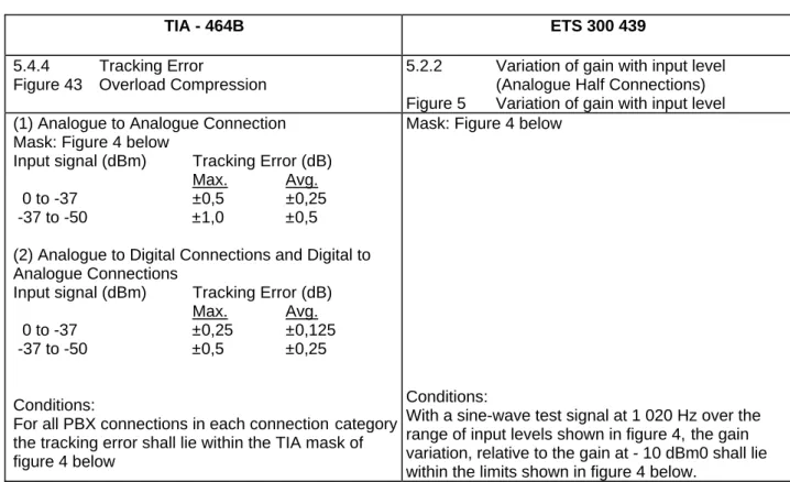
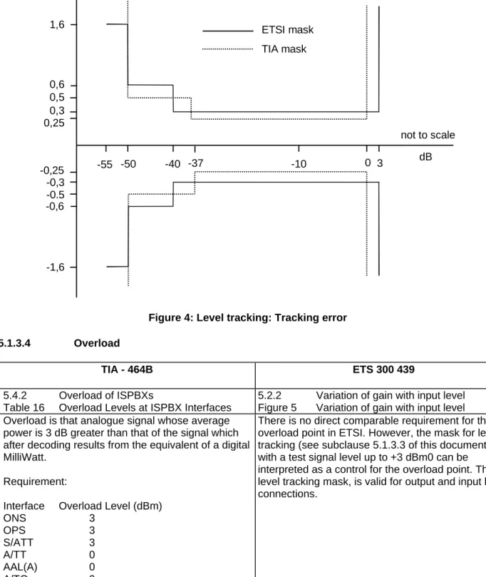
5.1.3.3 Level tracking: Tracking error
TIA - 464B ETS 300 439
5.4.4 Tracking Error
Figure 43 Overload Compression
5.2.2 Variation of gain with input level (Analogue Half Connections) Figure 5 Variation of gain with input level (1) Analogue to Analogue Connection
Mask: Figure 4 below
Input signal (dBm) Tracking Error (dB)
Max. Avg.
0 to -37 ±0,5 ±0,25
-37 to -50 ±1,0 ±0,5
(2) Analogue to Digital Connections and Digital to Analogue Connections
Input signal (dBm) Tracking Error (dB)
Max. Avg.
0 to -37 ±0,25 ±0,125
-37 to -50 ±0,5 ±0,25
Conditions:
For all PBX connections in each connectioncategory the tracking error shall lie within the TIA mask of figure 4 below
Mask: Figure 4 below
Conditions:
With a sine-wave test signal at 1 020 Hz over the range of input levels shown in figure 4,the gain variation, relative to the gain at - 10 dBm0 shall lie within the limits shown in figure 4 below.
Analysis: ETSI requirements cover a wider range of input levels than TIA; however, where the ranges overlap, TIA is tighter except for the input range of -37 to -40 dBm0.
Remark: TIA does not define Tracking Error with respect to a reference input level. If the limits must be interpreted as absolute total loss deviations, in contrast to the deviation referred to the loss at a specific input level (0 dBm or -10 dBm), then ETSI and TIA requirements are not comparable.
1,6 0,6 0,5 0,3 0,25 -0,25 -0,3 -0.5 -0,6 -1,6 -55 -50 -40 -37 -10 0 3 dB not to scale ETSI mask TIA mask
Figure 4: Level tracking: Tracking error 5.1.3.4 Overload
TIA - 464B ETS 300 439
5.4.2 Overload of ISPBXs
Table 16 Overload Levels at ISPBX Interfaces
5.2.2 Variation of gain with input level Figure 5 Variation of gain with input level Overload is that analogue signal whose average
power is 3 dB greater than that of the signal which after decoding results from the equivalent of a digital MilliWatt.
Requirement:
Interface Overload Level (dBm)
ONS 3 OPS 3 S/ATT 3 A/TT 0 AAL(A) 0 A/TO 0
There is no direct comparable requirement for the overload point in ETSI. However, the mask for level tracking (see subclause 5.1.3.3 of this document) with a test signal level up to +3 dBm0 can be interpreted as a control for the overload point. The level tracking mask, is valid for output and input half connections.
Analysis: Overload limits in ETSI are related to the Li and Lo parameters. Consequently, these limits would be country-specific as well as port specific. In TIA the overload point is only specified for the output as an absolute level +3 dB above the port specific output level OL:
OL = Li+ 3 OL = Lo + 3
5.1.3.5 Level tracking: Overload compression
TIA - 464B ETS 300 439
5.4.3 Overload Compression Figure 43 Overload Compression
No comparable requirement Overload Compression requirements are shown in
Figure 5 below Conditions:
To be met on 95 % of station-station, station-trunk, and trunk-trunk connections
Deviation is relative to 1 kHz Analysis: None -1 0 1 2 3 4 5 6 7 8 9 0 3 6 9 Acceptable Region
Fundamental input power (dBm)
Output Power (dBm)
not to scale
5.1.3.6 Signal levels
TIA - 464B ETS 300 439
5.9 Signal Levels No comparable requirement
The PBX shall comply with FCC Part 68, Section 68.308, for the following signal level limitations: (1) In-band Signal Power Limits
(a) Internal Signal Sources Not Intended for Network Control Signalling. (b) Internal Signal Sources Intended
Primarily for Network Control Signalling. (c) Through Transmission.
(d) Idle State Circuit Stability for Tie Trunks.
(e) Metallic Signal Power at Frequencies in the range 3 995 to 4 005 Hz.
(f) Longitudinal Voltage in the 100-to 4 000 Hz Frequency Range. (2) Out-of-band Signal Voltage Limits
(a) Metallic Voltage. (b) Longitudinal Voltage. Conditions:
The above signal limitations apply to:
(1) Analogue Access Lines with analogue ISPBX (ground start, loop start, DID).
(2) OPS Lines.
(3) Analogue Tie Trunks.
Analysis: Comparison Not applicable. In Europe the signal levels are considered as parameters, which may cause harm to the (public) network. Since ETSI, as a general rule, is specifying those parameters in separate "Access Requirements", these requirements are no more part of this standard. They are contained in TBRs or, (mainly in case of analogue access) part of national regulation.
A comparison between these regulations and FCC Part 68 is outside the scope of this document.
5.1.4 Hybrid balance
TIA - 464B ETS 300 439
5.5.1 Hybrid Balance Requirements Table 18 ISPBX Minimum Hybrid Balance
Requirements
3.1.6.1 Terminal Balance Return Loss (TBRL) (definition)
5.9.1 Terminal Balance Return Loss (for 2-wire analogue interfaces)
Figure 12 Limits for TBRL All Ports Template figure 6 below
Freq. Range (Hz) Hybrid Balance (dB) 500 - 2 500 > 22
200 - 500 equal to or greater than the values located on a straight line intersecting 17 dB at 200 Hz and 22 dB at 500 Hz
2 500 - 3 400 equal to or greater than the values located on a straight line intersecting 22 dB at 2 500 Hz and 17 dB at 3 400 Hz
Lines plotted on a log/linear scale Conditions:
Measurement procedure outlined in section 5.5.2. Test configurations shown in figures 45 (full channel method) and 46 (half channel method).
Template: Figure 6 below Freq. Range (Hz) TBRL (dB) 500 - 2 500 > 20
300 - 500 equal to or greater than the values located on a straight line intersecting 16 dB at 300 Hz and 20 dB at 500 Hz
2 500 - 3 400 equal to or greater than the values located on a straight line intersecting 20 dB at 2 500 Hz and 16 dB at 3 400 Hz
Lines plotted on a log/linear scale Conditions:
Test Procedure outlined in annex A (A.4.3.2).
Analysis: For all ports, the TIA requirement is more stringent than the ETSI requirement.
14 15 16 17 18 19 20 21 22 100 200 300 500 2500 3400 not to scale Hz ETSI (min TBRL)
TIA (min. hybrid balance) dB
5.1.5 Input Impedance
TIA - 464B ETS 300 439
5.5.3 Input Impedance Requirements Table 19 ISPBX Input Impedance Requirements
5.1 Nominal Value
Figure 4 Minimum value of return loss against the nominal PABX impedance
All Ports Template: Figure 7 below Freq. Range (Hz) Mandatory Z-in (dB) 500 - 2 500 > 22
200 - 500 equal to or greater than the values located on a straight line intersecting 14 dB at 200 Hz and 22 dB at 500 Hz
2 500 - 3 400 equal to or greater than the values located on a straight line intersecting 22 dB at 2 500 Hz and 14 dB at 3 400 Hz
Conditions:
To be met on 95 % of each connection type Reference Imp. is 600 Ω; for OPS, CO trunk & DID trunks, 600 Ω//2.16 µF is acceptable. Optionally, ONS reference impedance may be a three-element network either that used for hybrid balance or the ETSI nominal input impedance network
Test configurations given in figures 47 to 50 for 2-wire & 4-wire ports.
Impedance
Nominal PBX Impedance:
2-wire ports: 270 Ω + (750 Ω || 150 nF)
4-wire ports: 600 Ω
Return Loss: Template: Figure 7 below Freq. Range (Hz) TBRL (dB)
500 - 2 000 > 18
300 - 500 equal to or greater than the values located on a straight line intersecting 14 dB at 300 Hz and 18 dB at 500 Hz
2 000 - 3 400 equal to or greater than the values located on a straight line intersecting 18 dB at 2 000 Hz and 14 dB at 3 400 Hz
Conditions:
Measured against the nominal PABX impedance (270 Ω+(750 Ω || 150 nF); however, country specific PABX input impedance values given in annex A. Test Procedure for return loss outlined in annex A (A.4.3.1).
Analysis: ETSI requirements are less stringent than TIA for all frequencies.
Measurement conditions differ; TIA connections measured through PBX to 4-wire port with 600 Ω termination. ETSI connections measured half-channel, with open loop inside the PABX to avoid signal reflections.
10 12 14 16 18 20 22 100 200 300 500 2500 3400 not to scale Hz ETSI (min input impedance return loss)
TIA (min. input impedance return loss)
2000 dB
5.1.6 Echo loss
TIA - 464B ETS 300 439
Annex D: Loss Definitions. 3.1.6.3 Echo Loss.
The Echo Return Loss is defined as the weighted average of the Return Loss (or Transhybrid Loss) values over the frequency range from 400 to
3 400 Hz. The formula and the weighting factors are given: This definition is informative only.
Conditions:
For calculation of Echo Loss sub-multiples of 8 kHz should be avoided. A table with 16 frequencies, following this conversion should be used.
The Echo Loss is defined as the semi-loop loss averaged with 1/f power weighting over the telephone band. Reference is made to ITU-T Recommendation G.122 [1], paragraph 4 with the corresponding weighting algorithm.ETSI is giving only the definition of Echo Loss,no numerical requirements.
Conditions:
Calculation of Echo Loss is based on the values of semi-loop loss in the band 300 to 3 400 Hz, using the given formula or the trapezoidal rule given in G.122.
Analysis: In both cases, TIA and ETSI the Echo Loss is defined as a weighted average of the Return Loss or Trans-hybrid Loss of all equipment forming an echo source. This is resulting in one single value of Echo Loss to be used mainly for planning purposes. The weighting algorithm are notcomparable.
5.1.7 Stability loss
TIA - 464B ETS 300 439
No comparable requirements. 3.1.6.2 Stability Loss (Definition).
5.9.2 Stability Loss (K2, L2, M2 interfaces). 8.5.1 Stability Loss of interfaces connected
to a KD interface.
8.5.2 Stability Loss of interfaces connected to a M4 or MD interfaces.
Annex A, A.4.3.2.
Conditions:
For calculation of Echo Loss submultiples of 8 kHz should be avoided. A table with 16 frequencies, following this conversion should be used.
The Stability Loss is defined as the Lossbetween the PBX test-points (3.1.6.2) of a half connection to a L2 or M2I interface with worst case terminating conditions simulated by a short circuit and adjusted for the relative input and output levels of these 2-wire interfaces (annex A, 4.3.2).
The values of the Stability Loss should be stated by the supplier, in the frequency range between 200 and 3 600 Hz (5.9.2 and 8.5.1). For connections with a KD interface the Stability Loss shall be at least 6 dB (8.5.2).
Analysis: ETSI is referred to ITU-T Recommendation G.122 [1], taking into account, that a private network, connected digitally to a public network, may provide the total Stability Loss of the entire pathacross the public network (5.9.2, note 3 of ETS 300 439).
5.2 Voice impairment parameters 5.2.1 Noise
5.2.1.1 Weighted noise
TIA - 464B ETS 300 439
5.6.1.1 C-Message Weighted Noise
Table 21 ISPBX C-Message Weighted Noise Requirements
5.4.1 Weighted Noise of Interfaces K2, M2 and M4 5.4.2 Weighted Noise of Interfaces with feeding
bridge Connection Mean (desirable) 95 % (mandatory)
(dBrnC) (dBrnC) analogue-to-analogue ≤16 ≤20 analogue-to-digital ≤15 ≤19
digital-to-analogue ≤9 ≤13
Conditions:
For ISPBXs, values apply regardless of the interface transmission level, except for AAL(A) which may exceed values by up to 3 dB if there is gain in the circuit. Test arrangement shown in figure 51
K2, M2 and M4 interfaces
(dBm0p) input connection with < -65.2 signalling on speech wires
input connection with < -67.0 signalling on separate wires
output connection with < -67.0 signalling on speech wires
output connection with < -70,0 signalling on separate wires
Interfaces with feeding bridge.
Limit for weighted noise is calculated for every input and output connection depending on the relative levels. Values are expressed in dBmp.
Conditions:
Measurement Method: Annex A (A 4.5.1)
Analysis: These requirements are not directly comparable because of different weightings and reference values. However, with respect to the reference the following conversion can be used:
Value in dBrnC - 90 = Value in dBmp
According to annex A to ITU-T Recommendation O.41 [4] the different readings due to the weighting filters can be neglected (0,5 dB for white noise), therefore the above conversion can be used in all practical applications. Furthermore comparison is difficult, since ETSI specifies noise limits for input and output connections in contrast to port-to-port connections in TIA also follows ITU-T Recommendations, taking into account, that noise is a combination of noise sources, each of which may be influenced by the adjustment of relative levels or may be level independent. Consequently, for interfaces with feeding bridge (L2 and some M-interfaces), the noise limits may differ for every interface.
5.2.1.2 3 kHz flat noise
TIA - 464B ETS 300 439
5.6.1.2 3 kHz Flat Noise for ISPBXs 5.4.3 Unweighted Noise of Interfaces K2, M2, L2, K4 and M4
50 % (dBrn) 95 % (dBrn) 3 kHz flat weighted noise ≤ 35 ≤ 39 Conditions:
For interface transmission levels other than0 dB, the requirement should be shifted by avalue that corresponds to the differencebetween the transmission level at that interface and 0 dB.
There are no requirements for unweighted noise.
5.2.1.3 Single frequency noise
TIA - 464B ETS 300 439
No comparable requirements. 5.4.5 Single Frequency Noise for interfaceK2, L2, M2 and M4.
The level of any "unwanted" single frequency (in particular the sampling frequency and its multiples), measured selectively with a bandwidth of 80 Hz from 4 kHz to 72 kHz shall notexceed -50 dBm0 at the interface of an output connection.
Conditions:
No test signals are inserted into the half connection during measurements.
Analysis: The term "unwanted" refers to self generated noise (5.4.5, note) as it may occur by the sampling frequency itself or by other noise source (e.g. dc - dc power supply) in correlation with thesampling process. Comparison with TIA not possible.
5.2.1.4 Spurious out of band signals
TIA - 464B ETS 300 439
5.4.1 Frequency Response 5.8 Spurious out of band signals receivedat the K2, L2, M2 and M4 outputinterface.
Although not directly comparable, limits for signals above 4 kHz (out of band) are contained in the frequency response masks in section 5.4.1. For connection between analogue interfaces in the range from 4 000 Hz to 4 600 Hz the minimum loss, relative to the loss at 1 004 Hz should follow the equation:
-32*(SIN[π*(4 000-F)/1 200]+28)
In the range of 4 600 Hz to 12 000 Hz, the minimum loss, relative to the loss at 1 004 Hz is 60 dB. For analogue-to-digital and digital-to analogue connections, the minimum relative loss in the range 4 000 Hz to 4 600 Hz is described by the following equations, respectively:
-18*(SIN[π*(4 000-F)/1 200]-7/9) A-to-D -14*(SIN[π*(4 000-F)/1 200]-1) D-to-A
In the range of 4 600 Hz to 12 000 Hz, the minimum loss, relative to the loss at 1 004 Hz is 32 dB, A-to-D and 28 dB, A-to-D-toA.
Conditions:
See also section 5.1.2 of this document.
There are no requirements with respect to received out of band signals at the output of all types of analogue interfaces. Those requirements are subject to access requirements (TBRs) and therefore not part of this standard.
Analysis: There are no directly comparable requirements for out of band signals received at the output ports of a connection. However, values for minimum relative loss in the range from 4 kHz to 12 kHz in the frequency response masks of TIA 464-B, section 5.4.1 can be interpreted as limits for out of bandsignals.
5.2.2 Balance
5.2.2.1 Longitudinal to metallic balance
TIA - 464B ETS 300 439
5.6.2.1 Longitudinal-to-Metallic Balance
Table 22 ISPBX Longitudinal-to-Metallic Balance Requirements
Figure 52 Longitudinal Balance Limits
Requirements not given
Frequency Minimum Average
Balance Balance
(Hertz) (dB) (dB)
200 - 1 000 58 63
1 000 - 3 000 58 to 53 63 to 58 Conditions:
TIA considers longitudinal- to - metallic balance as a performance parameter for measuring product immunity against the conversion of disturbing longitudinal voltage into unwanted metallic noise. It applies to CO trunk loop/ground start, reverse battery (DID) trunks and OPS lines. Figure 52 shows a "desirable" region for average balance.
Analysis: Comparison not applicable. However, from previous ETSI standards (I-ETS 300 004), the LCL requirement was about 18 dB less stringent than the TIA requirement. In Europe the longitudinal - to - metallic balance is considered as a parameter, which may cause harm to the (public) network. Since ETSI, as a general rule, specifies those parameters in separate "Access Requirements", these requirements are not part of this standard. They are contained in TBRs or, (mainly in case of analogue access) part of national regulation. Also high LCL may indirectly be required to meet the immunity requirements called for under the European EMC Directive.
5.2.2.2 Transverse balance
TIA - 464B ETS 300 439
5.6.2.2 Transverse Balance
Table 23 Transverse Balance Requirements
Requirements not given Interface State Frequency Minimum
Range Balance (Hertz) (dB) CO Trunk On-Hook 200 - 1 000 ≥60 Loop Start 1 000 - 4 000 ≥60 Off-hook 200 - 4 000 ≥40 CO Trunk Off-hook 200 - 4 000 ≥40 Ground Start Reverse Battery Off-hook 200 - 4 000 ≥40 (DID)
OPS Line Off-hook 200 - 4 000 ≥40 NOTE: these are regulatory requirements Conditions:
The TIA requirements are taken directly from the FCC Part 68 technical requirements to protect the network from harm caused by the conversion of metallic signals into longitudinal signals that could cause excessive noise in other pairs of a multi-pair cable. The requirement defines ten measurement conditions, together with a transverse balance test circuit and termination schematics.
See also subclause 5.2.2.1 of this document
Analysis: Comparison not applicable. However, from previous ETSI standards (I-ETS 300 004), the LCTL requirement wasnearly identical to the TIA requirement in the off-hook case.
5.2.3 Crosstalk
TIA - 464B ETS 300 439
5.6.3 Crosstalk 5.5 Crosstalk
Between any Between any Between any
established established established
connection connection connection
and any and at least and at least
other 95 % of all 95 % of all
connection other other
connections connections (mandatory) (desirable)
(dB) (dB) (dB)
≥ 70 ≥ 75 ≥ 80
Conditions:
Full channel tests for every combination of through connection, for all interface categories over the 200 to 3 200 Hz frequency band.
Test circuit shown in figure 57.
Connection Type (dBm0)
Input (FEXT), all Interf. < -73 Input (NEXT), M4, 4w-2w < -73 Input (NEXT), L2, K2 < -73 *) Output (FEXT), M4, 4w-2w < -73 Output (FEXT), L2, K2 < -73 *) Output (NEXT), L2, all M int. < -73 Output (NEXT) between K2 < -66 *) Values specified in dBm
NEXT: Near End Crosstalk FEXT: Far End Crosstalk Conditions:
Measurement details are in annex A (A.5.4)
Requirements measured as "Crosstalk-Level" for an input signal of 1 020 Hz with a level of 0 dBm0.
Analysis: TIA does not specify the input level, but when the ETSI input signal level is applied the TIA requirement is about 3 to 5 dB more stringent than TIA measurement conditions, if liberally interpreted, requires a near-infinite number of test. The ETSI requirement is more detailed but the test conditions more practical.
5.2.4 Distortion
5.2.4.1 Quantization distortion
TIA - 464B ETS 300 439
5.6.4 Quantization Distortion
Table 24 ISPBX Quantization Distortion Requirements
5.6 Total Distortion including Quantizing Distortion Figure. 8 - 11Limits for signal-to-total distortion
ratio (various interfaces/conditions) Figure. 8.3 Quantizing Distortion Units (QDU). Input Signal Input/Output Input/Output
Level (dBm) Level Ratio Level Ratio (mandatory) (desirable) Analogue-to-Analogue Connection
0 to -30 ≥ 33 ≥ 37
-40 ≥ 27 ≥ 31
-45 ≥ 22 ≥ 26
Digital-to-Analogue and Analogue-to-Digital Connections
0 to -30 ≥ 35
---40 ≥ 29
---45 ≥ 25
--Conditions:
To be met on 95 % of connections in each category. Input: 1 kHz sine wave. Output: C message weighted distortion level.
Input Minimum Signal to Total Level Distortion Ratio
dBm0 Input- or output connection
A B 0 35,0 35,0 -20 35,0 35,0 -30 35,0 33,8 -40 29,0 26,5 -45 24,0 21,5
A : For Interfaces with signalling on separate wires
B : For Interfaces with signalling on the speech wires
For interfaces with feeding bridge, the curves are calculated on the basis of different noise sources (see also subclause 5.2.1 of this document) Conditions:
Measured with a sine wave signal of 1 020 Hz. A connection between two analogue interfaces and without an inserted digital loss pad or with a pad of 6.02 dB, is forming 1 Quantizing Distortion Unit (QDU). The number of QDU for a connection shall be stated by the supplier.
Analysis: Some of the ETSI requirements are virtually identical to the TIA half channel requirements, while others are less stringent. The coding schemes and weightings are different and the test methods are also different. In practice, it is not possible to measure quantization distortion alone because of the presence of other sources of distortions, such as noise. Therefore in ETSI this parameter is called "Total Distortion including Quantizing Distortion".
5.2.4.2 Single frequency distortion
TIA - 464B ETS 300 439
5.6.5 Single-Frequency Distortion for ISPBXs 5.7.1 Input signals above 4,6 kHz 5.7.2 Signals below 300 Hz ≤ - 28 dBm
Conditions:
For each connection category, 95 % of connections shall meet the above requirements. Input: any single frequency in the range of 0 to 12 kHz at a constant 0 dBm level. Output: at any other single frequency. Adjust input level if overload the point differs from +3 dBm.
For an input signal in the range from 4,6 to 72 kHz with a level of - 25 dBm0 any image frequency produced in the time slot of an input connection shall be at least 25 dB below the test level. No
requirements for input signals below 300 Hz. Conditions:
Test method given in annex A (A.5.2.1.6).
Analysis: These requirements are not directly comparable due to the differences in input level and frequency range, but at least part of their intents are the same. Ignoring the differences, the TIA requirement is 3 dB more stringent.
5.2.5 Delay
5.2.5.1 Echo path delay
TIA - 464B ETS 300 439
5.5.5 Echo Path Delay
Table 20 Echo Path Delay for ISPBXs
3.1.9.3 Mean One Way Transmission Time (Definition)
8.4 Mean One Way Transmission Time
Connection Round Trip Delay (ms)
1. Station-Station 3,0
2. Station-Analogue Trk 3,0
3. An. Trk-An. Trk 3,0
4. Station-Digital I/F 2,4 5. An. Trk-Digital I/F 2,4 6. Dig. I/F-Dig. I/F 2,0 Conditions:
Requirement for all frequencies in range of 300 -3 400 Hz. For each connection category, 95 % of connections shall meet the above requirements.
No numeric requirement for Echo Path Delay
The mean one way transmission time in a connection between two interfaces shall be a value stated be the supplier.
Analysis: ETSI requirements have shifted from specifying mandatory upper limits to the echo path delay to complete deletion of numeric values. Subsequent to the publication of the TIA standard, similar action is taking place in TIA.
5.3 Loudness levels
TIA - 464B ETS 300 439
5.3.2 Acoustic Reference Levels
Table 15 Interface Acoustic Reference Values for ISPBX
Annex C. Acoustic Reference Level Plan Description and Rationale
7.2.2 Sending and Receiving Loudness Ratings (SLR and RLR) [for 3,1 kHz handset system specific telephones]
Nominal Acoustic Reference Values treat the PBX / line port combination as a single system for defining loudness ratings at PBX interfaces. The values are presented in table 4. Background and application of the ARLP for system loss design is given in part 4.3.1.
Sending and receiving loudness ratings (SLR and RLR) of system specific telephones shall be stated by the manufacturer.
Analysis: Requirements are not directly comparable. The TIA requirements address the ISPBX with its terminal as a "black Box" where the requirements are given at the interface to external connections. Section 7.2.2 of ETS 300 439 addresses system specific handsets (i.e. not telephones connected to an L interface) with the SLR and RLR values referred to the PBX digital test point.
However, the requirements are related. The overall objective is that of providing satisfactory end-to-end transmission quality for nearly every call via all categories of external connection. The TIA requirements are designed to optimize the loudness levels at each such connection interface regardless of the terminal loudness values. With respect to ETSI requirements, it would be expected that thesupplier-specified loudness values of a system-specific handset, together with the supplier-specified port-to-port loss for each ISPBX connection involving that handset (see subclause 4.1.1 of ETS 300 439), will be such that the resulting system interface levels are optimized for end-to-end transmission performance.
Moreover, the TIA acoustic reference level plan (ARLP) is built on the premise that the loudness characteristics of a standard, i.e. non-proprietary telephone (in the TIA market) when connected to the ISPBX, together with the TIA Loss Plan (see table 1) loss for connections between such a telephone and any external connection port, results in near-optimum loudness values at each such port. Thus, for connections between a system-specific telephone and an external port, the loss plan design objective for the ISPBX connection between that telephone and the external port is to achieve loudness levels equivalent to those resulting from a connection between a standard telephone and that port. Within the framework of ETSI requirements, then, it would be reasonable to expect a supplier to design the loss plan for connections to system-specific handsets such that the system loudness levels at each port are equivalent to those when the port is connected to an L interface.
In developing the TIA Acoustic Reference Level Plan, the following characteristics have been assumedfor standard (TIA) analogue sets at a PBX line port:
TOLR: -49 dB nominal ROLR: +45 dB nominal
Using the relationships between IEEE and ITU units of SLR = TOLR +56, RLR = ROLR - 50, the ITUequivalents to the above values are:
SLR: +7 dB nominal RLR: -5 dB nominal
The ETSI analogue port (L interface) values are market-specific and will generally differ from the above TIA values.
Table 4: TIA-464B Acoustic Reference Levels (note 1) ISPBX Interface Port
designation
TOLR (dB) ROLR (dB) ERL(A)
(dB Min. Nom. Max. Min. Nom. Max.
On-premises line (note 2) (from ONS port)
ONS -48 -43 -38 46 51 56 N/A
On-premises line (note 2) (from ICS port)
ONS -45 -40 -32 49 54 59 N/A
ISDN-compatible line ICS -54 -46 -38 43 51 56 N/A
Off-premises line OPS -51 -46 -38 43 48 53 N/A
Analogue tie trunk A/TT -51 -46 -38 43 48 53 18
Digital tie trunk (note 3) ISD/TT -51 -46 -38 49 54 59 24
Analogue CO trunk AAL(A) -54 -49 -41 40 45 50 12
Digital CO trunk (note 4) AAL(D) -51 -46 -38 43 48 53 18
Analogue TO trunk A/TO -48 -43 -35 46 51 56 24
Satellite tie trunk S/ATT,
S/DTT
-51 -46 -38 43 48 53 18
Integrated services trunk IST -51 -46 -38 46 51 56 21
NOTE 1: The values in this table pertain to connections between the designated interface and an ONSor ICS port. Tolerances on ROLR and on ONS port TOLR are assumed to be ± 5,0 dB; to be compatible with the TOLR tolerance range for ISDN terminals, the maximum TOLR values inthis table are extended to nominal +8 dB. For this reason, the TOLR ranges for the two ONScases (first two rows) are dissimilar.
NOTE 2: For an ONS interface, the ARLP requirements differ between connection to another ONS portor to an ICS port; reflecting the intent to align ICS connections to equivalent loudness onintra-PBX connections.
NOTE 3: For connections from ICS to ISD/TT, ROLR values are +46, +51, +56 dB respectively. NOTE 4: The ARLP requirement for the AAL(D) interface is intended to be compatible with
current PSTNoperation; specifically, that on all connections to a PBX, the DEO inserts the required public network loss (e.g. 6 dB receive-side loss for connections to a digital tandem connecting trunk).This is sometimes referred to as the pre-ISDN environment. Guidelines in Loss Plan for Evolving Digital Networks. ANSI Standard T1.508 are expected to lead to a change in operation of PSTN switched such that digital connections to a PBX will be provided with no inserted loss in order to accommodate ISDN terminals with bit-transparent end-to-end connections. In this (ISDN) environment, the ARLP requirement for the AAL(D) interface will be redefined to be thosefor IST.
5.3.1 Acoustic reference level plan 5.3.1.1 ARLP Background
The extension of digital technology to terminals, together with the increased diversity of terminal characteristics and the gradual trend towards all-digital connections within the ISDN environment, indicates the need for a flexible loss/level planning approach based on specified acoustic levels at defined PBX external interfaces rather than on simple electrical losses. This approach is based on a systems view, wherein station apparatus and the PBX are considered as a whole, with the loss plan described in terms of an acoustic (user) to electrical (network) standard. The concept of defining a loss level plan in such terms is called the Acoustic Reference Level Plan (ARLP).
The ARLP, when applied to private network voice terminals, provides advantages with respect to terminal design as well as to network planning. Among these are:
- Any connection of a given class and type will have a known terminal-to-terminal acoustic loss or range of loss;
- The installation on the terminal side of the interface at which the acoustic levels are specified may be considered as a single system for design purposes, thus enabling the supplier to optimize the selection of acoustic and electrical parameters for any given set and switch that combine to achieve the specified acoustic levels at the interface;
- Standardization of systems and demonstration of compliance will be simplified;
- Networking will be made easier with respect to assessing transmission performance; for example, the impact of alternate routing strategies on end-to-end acoustic loss can be identified.
5.3.1.2 Acoustic Reference Level Plan Description
The ARLP applies to voice terminal interfaces for connections between a facility and a terminating device (e.g. a station set). The basic ARLP requirements do not apply to tandem connections between trunks and access lines. However, for transmission analysis purposes, the acoustic levels from a defined ARLP interface can be extrapolated to any point along a connection.
In the PBX environment, the ARLPP defines levels at the PBX interface to tie trunks and public network access lines (PBX-CO trunks) when such facilities are connected through the PBX to station apparatus. Trunks and access lines may be analogue or digital. Public network access lines generally connect to a local exchange office but may also connect to other public network providers. Station apparatus may consist of standard telephone instruments, ISDN-compatible digital terminals, or proprietary terminals, analogue or digital. The interface for analogue terminals may utilize technologies for optimizing power consumption, e.g. constant current feed arrangements, thereby altering the traditional electro-acoustic characteristics; the use of local powering could also alter these characteristics.
Since the ARLP is defined at the facility interface, the electrical loss within the PBX for connections to station interfaces is not explicitly specified by the plan. In actual implementation, it is expected that the ARLP provisions will be met via a combination of station apparatus electro-acoustic transducer efficiencies and inserted electrical loss in the PBX. The ARLP gives the system supplier the flexibility to tailor electrical loss insertion to accommodate unique station characteristics that differ from those of standard telephone sets, and yet be in compliance with loss plan standards.
The electrical loss insertion specified in a PBX loss plan generally assures that adequate echo return losses exist at connection ends. Dissociating the electrical loss from the ARLP requirements necessitates that an explicit specification be included to ensure echo performance. The ARLP therefore, includes requirements on minimum echo return loss (ERL) as seen at the interface.
5.3.1.3 ARLP Loss Design Application for System-Specific Telephones
System-specific telephone sets should provide electro-acoustic performance equivalent to that of standard telephone sets connected to ISPBX line ports. In the figure 8 below, parameters X and Y represent, respectively, TOLR and ROLR values (as defined by the Acoustic Reference Level Plan) at interface T. Parameters M and N represent electrical losses in the ISPBX (table A1-1) which, with the standard telephone nominal loudness levels, result in the loudness values X and Y. Parameter Q and R represent supplier-specified electrical losses which, with the system-specific set loudness values P and S, result in the values X and Y.
TOLR: -49 ROLR: +45 TOLRP: P ROLR: S X Y -49+M=X +45+N=Y P+Q=X S+R=Y Standard set System-specific set ISPBX T
Figure 8: Equivalency of System-specific Sets to Standard Sets (loss design for connections between sets and interface T)
5.4 Other impairment parameters 5.4.1 Inter-modulation distortion
TIA - 464B ETS 300 439
5.7.1 Inter-modulation Distortion
Table 25 Inter-modulation Distortion Limits for PBXs
Requirements not given.
Connection Distortion Limits
Interface (dB below received level)
Categories (R2) (R3) Up to 4.8 kb/s data 39 51 Up to 9.6 kb/s data 46 56 Conditions:
Intermodulation is measured using four-tone method that employs two pairs of equal-level tones transmitted at a total, composite power level of 13 dBm. One Pair at 857 and 863 Hz, the second pair at 1 372 and 1 388 Hz. Intermodulation distortion is measured as the second-order (R2) and third-order (R3) products resulting from the application of the four tones.
R2 is the average power level in the 503-to-537 Hz and 2 223-to-2 257 Hz frequency bands, expressed in dB below the received power level. R3 is the average power level in the 1 877-to-1 923 Hz frequency bands, expressed in dB below the received power level.
Analysis: Comparison not applicable. Inter-modulation or harmonic distortion is caused by non-linearity present in the electric-to-electric transfer function of the PBX. This form of distortion is of primary concern to the transmission of data. ITU-T G.712 [3] and Q.517 [5] Recommendations noted that theinter-modulation distortion are in practice always met if the requirements according to total distortion including quantization distortion and variation of gain with input level are met. In ETSI this requirements omitted due to these issues in the ITU-T Recommendations.
5.4.2 Group delay distortion
TIA - 464B ETS 300 439
5.7.2.2 Relative Envelope Delay (RED) Figure 58 Relative Envelope Delay vs frequency
5.3 Group Delay Distortion For Station-to-Trunk and Trunk-to-Trunk interface the
Relative Envelope Delay (RED) shall lie below the following values:
Frequency (Hz) Mandatory Desirable RED in us RED in µs 500 -- 300 800 375 150 1 000 190 75 1 150 150 75 2 300 150 75 2 500 190 75 2 700 375 150 3 000 -- 300
For Station-to-Station twice the RED values are permitted.
Conditions:
For each connection category, 95 % of connections shall meet the above requirements. The test signal is a carrier 50 % amplitude modulated with a sinusoidal frequency of 83,3 Hz.
No requirements.
Analysis: In ETSI Group Delay Distortion is considered as an impairment mainly to non voice or data transmission. Since ETS 300 439 does not apply to services other than 3,1 kHz voice telephony (see clause 1), requirements for this parameter are not contained in this standard.
5.4.3 Impulsive noise
TIA - 464B ETS 300 439
5.7.4 Impulsive Noise. 5.4.4 Impulsive Noise for interface K2, L2, M2 and M4.
On 95 % or more of all connections through each connection category, the impulsive noise level shall not exceed zero counts above a threshold of 55 dBrnC in a measurement interval of 5 minutes. It is desirable not to exceed a noise level of 47 dBrnC. Conditions:
Impulsive Noise limits shall be met under fully loaded busy-hour PBX traffic condition.
No requirement for Impulsive Noise.
Analysis: In ETSI, Impulsive Noise is considered as an impairment only to non-voice and data transmission through a PBX. Since ETS 400 439 does not apply to services other than 3,1 kHz voice telephony (see clause 1), requirements for Impulsive Noise are not contained in this standard.