© 2019, IRJET | Impact Factor value: 7.211 | ISO 9001:2008 Certified Journal
| Page 5744
ELECTROMAGNETIC BRAKING SYSTEM
Pratyush Kumar Routh
1, Prem Sagar
2, Prince Kumar
3, Rajesh Kumar
4, Sarnendu Paul
51,2,3,4
FINAL YEAR, DEPARTMENT OF MECHANICAL ENGINEERING, ASANSOL ENGINEERING COLLEGE, ASANSOL,
WEST BENGAL, INDIA
5
ASSISSTANT PROFESSOR, DEPARTMENT OF MECHANICAL ENGINEERING, ASANSOL ENGINEERING COLLEGE,
ASANSOL, WEST BENGAL, INDIA
---***---Abstract - This project aims to create an electromagnetic
braking system model capable of applying brakes without any friction loss and without losing the energy supplied. It uses a two electromagnets which runs by the supply of power from the circuit. Also, there is a wheel which is attached to the motor so when the power the supplied, by the help of motor the wheel rotates. Then a fan is attached near electromagnets to cool the electromagnets from excessive heating. A metal bar is in the vicinity of the electromagnets and wheel so when the electromagnets produces eddy currents which stops the rotating wheel or rotor. This model helps in a way to be a used a retardation equipment in vehicles.Key Words: Electromagnet, Flux, Wear, Eddy Current, Fade
1. INTRODUCTION
Electromagnetic brakes (also called electro-mechanical brakes or EM brakes) slow or stop motion using electromagnetic force to apply mechanical resistance (friction). The original name was "electro-mechanical brakes" but over the years the name changed to "electromagnetic brakes", referring to their actuation method. Since becoming popular in the mid-20th century especially in trains and trams, the variety of applications and brake designs has increased dramatically, but the basic operation remains the same. Electromagnetic brakes are the brakes working on the electric power & magnetic power. They works on the principle of electromagnetism. These brakes are an excellent replacement on the convectional brakes due to their many advantages. The reason for implementing this brake in automobiles is to reduce wear in brakes as it frictionless. Electromagnetic brakes are of today’s automobiles. The working principle of this system is that when the magnetic flux passes through and perpendicular to the rotating wheel the eddy current flows opposite to the rotating wheel/rotor direction. This eddy current trying to stop the rotating wheel or rotor. This results in the rotating wheel or rotor comes to rest/ neutral.
1.1 HISTORY
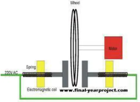
[image:1.612.327.569.455.632.2]It is found that electromagnetic brakes can develop a negative power which represents nearly twice the maximum power output of a typical engine, and at least three times the braking power of an exhaust brake. (Reverdin, 1994). These performance of electromagnetic brakes make them much more competitive candidate for alternative retardation equipment compared with other retarders. By using by using the electromagnetic brakes are supplementary retardation equipment, the friction brakes can be used less frequently, and therefore practically never reach high temperatures. The brake linings would last considerably longer before requiring maintenance and the potentially “brake fade” problem could be avoided. In research conducted by a truck manufacturer, it was proved that the electromagnetic brake assumed 80% of the duty which would otherwise have been demanded of the regular service brake (Reverdin, 1974). Furthermore the electromagnetic
Fig 1. Schematic Diagram of Principle of Electromagnetic Braking System
© 2019, IRJET | Impact Factor value: 7.211 | ISO 9001:2008 Certified Journal
| Page 5745
vehicle with 5 axles and weighting 40 tones powered by a powered by an engine of 310 BHP travelling down a gradient of 6% at a steady speed between 35 and 40 mph, it can be calculated that the braking power necessary to maintain this speed ot the order of 450 HP. The brakes, therefore, would have to absorb 300 HP, meaning that each brake in the 5 axels must absorb 30 HP, that a friction brake can normally absorb with self-destruction. The magnetic brake is well suited to such conditions since it will independently absorb more than 300 HP (Reverdin 1974). It therefore can exceed the requirements of continuous uninterrupted braking, leaving the friction brakes cool and ready for emergency braking in total safety. The installation of an electromagnetic brake is not very difficult if there is enough space between the gearbox and the rear axle. If did not need a subsidiary cooling system. It relay on the efficiency of engine components for its use, so do exhaust and hydrokinetic brakes. The exhaust brake is an on/off device and hydrokinetic brakes have very complex control system. The electromagnetic brake control system is an electric switching system which gives it superior controllability.
1.2Types of Braking Systems
Electromagnetic Brake System: A rising style of brake system, electromagnetic brakes use an electric motor that is included in the automobile which help the vehicle come to a stop. These types of brakes are in most hybrid vehicles and use an electric motor to charge the batteries and regenerative brakes. On occasion, some buses will use it as a secondary retarder brake.
Frictional Brake System: A frictional brake system is found in many automobiles. They are service brakes, and typically found in two forms; pads and shoes. As the name implies, these brakes use friction to stop the automobile from moving. They typically include a rotating device with a stationary pad and a rotating weather surface. On most band brakes the shoe will constrict and rub against the outside of the rotating drum, alternatively on a drum brake, a rotating drum with shoes will expand and rub against the inside of the drum.
Hydraulic Brake System: A hydraulic brake system is composed of a master cylinder that is fed by a reservoir of hydraulic braking fluid. This is connected by an assortment of metal pipes and rubber fittings which are attached to the cylinders of the wheels. The wheels contain two opposite pistons which are located on the band or drum brakes which pressure to push the pistons apart
forcing the brake pads into the cylinders, thus causing the wheel to stop moving.
1.3SIGNIFICANCES AND SCOPE
The following are the significances:
1. Electromagnetic brakes satisfy all the energy requirements of braking without the use of friction. They have better heat dissipation capability to avoid problems that friction brakes faces times.
2. They can also be used as a supplementary retardation equipment in addition to the regular friction brakes on heavy vehicles. 3. These brakes’ component cost is less so these
brakes are cheap.
4. They can be used as an alternative method for the future crisis of the crude oils.
1.4Limitations
The following are the limitations:
1. The installation of an electromagnetic brake is very difficult if there is not enough space between the gearbox and rear axle.
2. It cannot use grease or oil.
3. EM brakes are good at slowing things down, not completely stopping them.
2. METHODOLOGY
Basically, this project was to study and analyse electromagnetic braking system as a secondary measure for the hydraulic braking system. First, the base for the electromagnets and the stand for fitting the wheel, is made. Then, a wheel is made and attached to the spook whereas the spook is attached to the stand by the help of bearings. An electromagnet is made by winding the copper wire with the cylindrical body and attached to its base. Furthermore, a U shaped metal rod is welded with a L shaped metal bar forming a brake shoe and then its end are rest inside the electromagnet. The motor is attached to the base. So the electromagnet and the motors of wheel are circuited to an external battery and by turning it on, they work respectively.
2.1 Theoretical/Conceptual Framework
Our model is divided mainly into two different units:
1) Driving Unit.
© 2019, IRJET | Impact Factor value: 7.211 | ISO 9001:2008 Certified Journal
| Page 5746
1)
DRIVING UNIT
a.
Electric Motor:
An Electric motor is an electrical device that converts electrical energy into mechanical energy. In normal motoring mode, most electric motors operate through the interaction between an electric motor's magnetic field and winding currents to generate force within the motor. Electric motors may be classified by electric power source type, internal construction, application, type of motion output, and so on.b.
Wheel:
Wheel gets in motion with the help of running motor. Both motor and wheel is connected with the help of connecting chain and chain ring.
c.
Power Control:
This division consists of power supply to whole system and a separate power control system to control the motion of motion.
2)
BRAKING UNIT
a.
Electromagnet:
An electromagnet is a type of magnet in which the magnetic field is produced by an electric current .The magnetic field disappears when the current is turned off. Electromagnets usually consist of insulated wire wound into a coil. A current through the wire creates a magnetic field which is concentrated in the hole in the centre of the coil. The wire turns are often wound around a magnetic core.b.
Brake Shoe
: It is part that will stop the main wheel when the electromagnet is turned on.3)
OTHER PARTS
a.
Spring
: A coil spring, also known as a helical spring, is a mechanical device which is typically used to store energy and subsequently release it, to absorb shock, or to maintain a force between contacting surfaces. : Two compression springs are used to push back the brake shoe back in its position.b.
Bearing:
The purpose of Ball Bearing is to reduce rotational friction and support radial and axial loads.In this project 608 2RS type of bearing is used.2.2 WORKING MECHANISM
Fig.2: Flow chart of the working mechanism
3. FABRICATION
a.
Base plank
:
It consists of rectangular wooden plank which acts as a base for all the component of EMBS. It will have dimension of 80*50*1 cm.b.
Electricmotor
:
DC motors is used to move the wheel.c.
Electromagnet
:
In this project, we used electromagnet to stop the wheel. Basically, it made by winding the copper wire round the cylindrical body to required strength.3.1
Overall Fabrication of the System
Methodology to Fabrication of electromagnetic braking system model:
a. Analyse the problems in the fabrication of electromagnetic braking system
b. Designing the required components. c. Selection of required materials. d. Purchasing the materials. e. Fabrication of the electromagnet. f. Preparation of report and submit.
POWER ON
Motor runs and induces rotation in
the chain drive
Wheel starts rotating
Electromagnet is energized Rotation of wheel is
retarded Wheel stops
rotating
© 2019, IRJET | Impact Factor value: 7.211 | ISO 9001:2008 Certified Journal
| Page 5747
4. CALCULATIONS
Assume Data
Table1. Useful data
Sr.
No. Notations Value Meaning
1 M 12 kg Rotating mass
2 t 2.5 sec Brakingtime
3 d 0.276 m Wheel dia.
4 N 150 rpm Wheel rotational speed
5 R 1.725 Ratio of wheel diameter&
disc diameter
6 Rd 0.08m Discradius
7 µ 0.25 Coefficient of friction
8 Re 0.06m Effective disc radius
9 E 29.0 joules Total energy of rotating
mass
10 I 8 Amp-hr Current through coil
11 L 0.048m Length of solenoid
12 59.6 x 10⁶
S/m Electrical conductivity of disc
13 R 0.015 m Radius of electromagnet
14 V 12 V Battery Voltage
15 I 8 Amp-hr Battery Current
16 C 465 J/Kg0C Sp. Heat capacity of disc
17 K 54 watt/m0C Thermal conductivity of
disc
18 Volume 0.00003601
m3
Disc volume
19 Ρ 7850 kg/ m3 Density of disc
20 µo 4π x 10-7 Permeability of air
21 µs 2000 Permeability of steel
Braking force
The total braking force required can easily be calculated by using Newton’s Second law of Motion:
V = Π*d*N/60
= (Π x 0.276 x150)/60 =2.1666m/s
A= (v-u)/t = (2.1666-0)/2.5 =0.86664m/sec2
F= m*A=12 x 0.867=10.40N
Braking force
T = (Fx 0.5d)/R
= (10.40 x 0.5 x 0.276)/1.725 = 0.832Nm
Clamp force
C = T/ (µ x Re)
=0.832/(0.25 x 0.06) =55.46 N
Brake power
Assuming the stop is from the test speed down to zero then the kinetic energy is given by:- KE=0.5 x m x v2
=0.5x12x2.16662 =28.149336 Joules
Rotational Energy:
The rotational energy is the energy needed to slow rotating parts. It varies for different vehicles and which gear is selected however taking 3% of the kinetic energy is a reasonable assumption.The power is then given by:
P= E/t =29.0/2.5 =11.61watt
This is the average power. The peak power at the time of braking is double of this.
Brake heating
Fade Stop Temperature Rise
∆t = (P x t)/ (ρ x c x Volume)
= (11.61x2.5)/ (7850*465*3.601*10-5)
= 1.01900C
Magnetic flux density(B):
T=1/2**δ*π*R2*m2*B*z2*
( ) ]
= (0.5x59.6x106 x0.003x5π2 x 0.0152 x 0.0072 x B2) x
(1-(0.035/0.996))
B =18.01Wb/m2.
B = (µs x µo x n x I)/L
18.01 = (2000 x 4П x 10-7 x n x 8)/0.048
© 2019, IRJET | Impact Factor value: 7.211 | ISO 9001:2008 Certified Journal
| Page 5748
Magnetic field strength (H):
H = N x I/L
= (43 x 8)/ 0.048 =7166.66 A/m
Fig3. Cross-sectional view
5. CONCLUSION
This report presents the performance of an electromagnetic braking system which includes various components with its cost effectiveness and efficient methodologies to utilize the supplied energy. With the application of the effective and strong electromagnet we can have greater efficient braking system.
6. ACKNOWLEDGEMENT
I am highly indebted to the help of project supervisor and project coordinator of the department of Mechanical Engineering, Asansol Engineering College. I express heartily thank to the project group of ME 2019 batch, Asansol Engineering College providing with the help in the project. Thanks to all the classmates and faculty staff of department of Mechanical Engineering who helped directly and indirectly to carry out this project.
7. REFERENCES
1. Andreen, J.H., Gibson, J.W. and Wetmore, O.C., 1953. Fabric evaluations based on physiological measurements of comfort. Textile Research Journal, 23(1), pp.11-22.
2. Totala, N.B., Bhosle, P., Jarhad, S., Jadhav, S. and Kuchekar, K., 2015, April. Electromagnetic Braking System. In National Conference on Innovations in Mechanical Engineering (Vol. 6, p. 8).
3. Yadav, Y.K., Shah, A.K., Yadav, J.K. and Patel, J.P., 2018. Electromagnetic Braking System.
4. HOLT, A., 1986, June. Electromagnetic braking for Mars spacecraft. In 22nd Joint Propulsion Conference (p. 1588)
5. Prajapati, K., Vibhandik, R., Baria, D., Patel, Y. and Detail, I.G., 2017. ELECTROMAGNETIC BRAKING SYSTEM. International Journal of Scientific Research in Engineering, 1(3).
6. Patel, S., Patel, M., Patel, A., Sanghani, C., Patel, D., Patel, S.K., Patel, M.K., Patel, A.R., Sanghani, C.D. and Patel, D., 2015. Development of the Electro-Magnetic Brake. International Journal, 1, pp.485-492.
7. Flemming, Frank; Shapiro, Jessica (July 7, 2009). “Basics of Electromagnetic Brakes” .machine design : pp. 57–58
8. Auguston, Karen; Flemming, Frank (September 1999). "Floating ArmatureSpeeds Response"