'l: .. .r .'
50
.··· ..
. : ". :: .'·10
;'ii ~ ".': :. '." ."if.'" ..": ' '. .
. . .
. . . ~ . '
[):'ISKEJTE
'. . ,STOR'AG8U:ISIJT
;. ", .,:",., .. . .~ " '. "." -" .5010
DISKETTE STORAGE UNIT
REFERENCE MANUAL 400382
NOTE: Throughout.this documentation new model numbers are used. These refer to:
New Model Number
5100
5200
5010
5012
Previous Designation
DB8/1
068/2
DB8/4
REV I S ION RECORD
SECTION
1.0
1.1
2.0
3.0
3. 1
3.2 3.3 3.4 3.5 4.0 4. 1 4.2 4.3 4.4 4.5 4.6 5.0 5.10 5.11 5.12 5.13 5.14
DYNABYTE 5010 DISKETTE STORAGE UNIT REFERENCE MANUAL
TABLE OF CONTENTS
TITLE
Introduction
Assumption of Expertise
License Requirements
Installation
Initial Boot Up and Test
Di sk Control I er
Disk Format Compatibility
Computer Hardware Configuration Required
Conversion from 115VAC to 230VAC
ZASM Z80 Assembler
Introduction
Assembler Execution
Source Format
Error Messages
Loading the Object
Object File Format
DOS Revis ion 2.1
Introduction
How to Use Revision 2. I
FORMAT and UPDATE
SECTION 5.15 5.16 5.2 5.21 5.22 5.3 Figure
Figure 2
Table 1
TabJe 2
Table 2A
5.4
Table 3
Table 4
Table 5
Table 6
5.5
TABLE OF CONTENTS CONTINUED
TITLE PAGE
BAUD 37
FORMAT 38
Changing the CBIOS I/O Drivers 39
10BYTE 41
Error Messages 41
Operation of an Interconnected 5200 42
and 50JO
Ma in Cont roller Card Jumpers 43
AuxilIary Controller Card Jumpers 44
List of Software Included 45
with CP/M 2.1
Disk Formats 46
Skew Tables 47
Disk Storage of Dynabyte Systems 48
Patches to Format Rev 3 .O-B to 49
Change the Directory Size
Memory Map for 32K Memory Size 50
CSIOS Rev 2.1 Error Messages 51
PROM Usage in 50JO Systems and 52
Combined 50]0 and 5200 Systems
SECTION 6.05 6.06
7.0
I. 2. 3.4.
5.TABLE OF CONTENTS CONTI NUED
TITLE
Floppy Disk Controller, AuxilIary PCB
Auxillary Controller PCB, Block Diagram
User Comments
APPENDIX
DYNABYTE 5010 DISKETTE STORAGE UNIT SUMMARY SPECIFICATION
I ntroduct ion
Power Supply
Floppy Disk Drives
Description
Speci f i cat ion
Disk Controller
Description
Sped f i cat ion
REMEX Di sk Ddve
Maintenance Procedures
SHUGART Disk Drive
Maintenance Proc~dures
5010 DISKETTE STORAGE UNIT REFERENCE MANUAL
I .0 I NTRODUCT I ON
The 5010 is a floppy disk storage system for use with a S100
microcomputer. It contains two floppy disk drives and all the
electronics necessary for interfacing to a S100 bus computer. The
system may be expanded to include additional disk drives. It is
connected to the S100 computer by means of the disk controller
electronics. The disk controller is divided between two cards. One of these cards referred to as the AUX DISK CONTROLLER CARD is
mounted inside of the 5010 unit. The other card is referr·ed to as
the MAIN DISK CONTROLLER CARD and it is mounted in the 5100 bus computer. These cards are connected by a 50 conductor cable. Each AUX DISK CONTROLLER CARD can support up to 8 disk drives. Each
MAl N 0 I SK CONTROLLER CARD can support up to two AUX 0 I SK CONTROLLER
CARDS. This means that each main card can support up to 16 drives •
.
'--""-The 5010 has the ability to record data in either single or
doub 1 e dens i ty. I n the sing 1 e dens i ty mode the un i t ut iIi zes IBM
compatible 3740 soft sectored format. This provides 77 tracks of
storage. Each track contains 26 sectors of 128 bytes. This gives
a total formatted storage of 256,256 bytes per drive. Thus in
single density the 5010 provides a total storage capacity of 512,512
bytes. In the double density mode the format is not IBM compatible.
The number of tracks remains the same (77) but the number of sectors
on all but the outer two tracks is increased to 54. The sector length remains the same as single density (128 bytes). This gives
OYNABYTE 5010 OPERATING MANUAL ASSUMPTION OF EXPERTISE
1.1 ASSUMPTION OF EXPERTISE
The documentation suppl ied with the 5010 . assumes a certain
level of expertise on the part of the user. Specifically, it is assumed
that the user is:
1. Famililar with the concept of floppy disks as mass storage media.
2. Familiar with terminology commonly used in the data
processing ihdustry~
If the user does not possess this level of familiarity, it is highly recommended that he or she seek support from the agent through
2.0 LICENSE REQUIREMENTS
The operating software utilized by the 5010 is supplied under
license from Digital Research. This operating system is a version of CP/M called Dynabyte DOS Level 2.0.
IMPORTANT: All Digital Research programs are sold only on the condition
that the purchaser agrees to the following I icense. READ THISI,.ICENSE
CAREFULLY. If you do not agree to the terms contained in this license,
return the packaged diskette UNOPENED to your distributor and your
purchase price will be refunded. If you agree to the terms contained
in thisli'cense, fill out the REGISTRATION card which is in the pocket of this manual cover and RETURN to Dynabyte by mail.
DIGITAL RESEARCH agrees to grant and the customer agrees to accept on the following terms and conditions nontransferable and nonexclusive
1 icenses to use the software program(s) (1 icensed programs) herein
del iveredwith this agreement.
TERM: This agreement is effective from the date of receipt of the
above ... referenced programs and shall remain in force until terminated
by the customer upon one month's prior written notice, or by Digital
Research as provided below.
Any license under this agreement may be discontinued by the
LICENSE: Each program license granted under this agreement authorizes the customer to use the licensed program in any machine readable form
on any single computer system (referred to as system). A separate
license is required for.~each system on which the licensed program will
be used.
This agreement and any of the licenses, programs or materials to
which it appl ies may not be assigned, subl icensed or otherwise trans ..
ferred by the customer wi thoutpr lor written consent from Dig1 tal
Research. No right to print or copy, in whole or in part, the
licensed programs is granted except as hereinafter expressly provided.
PERM I 5S ION TO COPY OR MOD I FY II CENSED PROGRAMS: The customer sha 11
not copy, in whole or in part, any licensed programs which are pro"
vided by Digital Research in printed form under this agreement. Additional copies of printed materials may be acquired from Digital
Research.
Any licensed programs which are provided by Digital Research in machine readable form may be copied, in whole or in part, in printed or machine readable form in sufficient number for use by the
customer with the designated system, to understand the contents of such machine readable material, to modify the licensed program as provided below, for back .. up purposes, or for archive purposes,
pro-vided, however, that no more than five (5) printed copies wi 11 be in
existence under any license at anyone time without prior written
consent from Digital Research. The customer agrees to maintain appropriate records of the number and location of all such copies
of licensed programs. The original, and any copies of the licensed
program, in whole or in part, which are made by the customer shall be the property of Digital Research. This does not imply, of course,
material to form an updated work, provided that, upon discontinuance of the 1 icense' for such lIcensed program, the 1 icensed program suppl ied
"
by Digital Research will be completely removed from the updated work. Any portion of the licensed program included in an updated work shall be used only if on the designed system and shall remain subject to all other terms of the agreement.
You must return the postcard or form enclosed in this manual .(which is reproduced below) to Dynabyte.
Please read the software license agreement before opening the
diskette package. If you do not agree to the licensing contract,
you may return the system to your distributor for refund as long as the diskette package remains unopened. Upon receipt of this registration card QY Dynabyte, you will become a
registered CP/M owner and receive the following:
CP/M User's Newsletter
Notices of updates and enhancements to Digital Research Software
Digital Research Software Dug reports and patches
Discounts on updated versions of Digital Research Software
I have read the Digital Research Software Licensing Agreement and agree to abide by the terms contained in it:
DATE
---
CP/M Version---
Serial #---NAME _ _ _ - - - -_ _ _ _ S.IGNATURE _ _ _ _ _ _ _ _ _ _ _
COMPANY _ _ _ _ _ _ _ _ _ _ _ _ _ _ _ ~ _ _ _ _ _ _ _ _ _
ADDRESS
3.0 INSTALLATION
The 5010 is connected to the host computer by means of the
IIdisk controller card" (Dynabyte part #800:471) and a 50 conductor
flat ribbon cable. The Iidisk controller card" must be installed
in the host. If the ,5010 is shipped separatelytheli the "disk
controller cardl l is shipped with the ,5010 and must be installed
by the user in a suitable S-100 bus computer. The unit is supplied
with a length of ribbon caDle that is complete with the necessary
connectors attached to each end of the cable. The cable is symmetrical,
it does not matter which end of the cable is connected to the 5010
On~ end of the cable attaches to the 50 pin connector on the back of the 5010. This connector is labeled "FLOPPY DISK 1/011 • The
other end ,of the cable goes to the IIdisk controller card.11 If
the disk controller card is mounted in a computer other than a
OYNABYTE 5100 then 'the cable goes directly onto the connector on
top of the "diskcontroller card." If the "disk controller cardl l
is mounted in a 51QO. then the cable connects to a 50 pin connector
on 'the ba~k of the 5100.;. This connector is I abe I ed "FLOPPY 01 SK I/O .11
It is necessary to orient the cable properly. Pin 1 on the connector
must correspond wi th pin 1 on the mat i ng connectors at both ends.
If the "disk controller cardl l is used in a 51 GoO! then the ribbon
cable from the back panne) of the computer must be connected,to the
top of the card. The correct orientation is shown by aligning the
3. I
-.-;..;.--
INITIAL BOOT UP AND TEST---'
-
--
--'
1. After connecting the system as described above the following
steps should be followed carefully. This will test that the system
is operating properly and at the same time produce a copy of the
master diskette on a working diskette.
NOTE: Through this discussion the messages typed into
the system on the terminal or sent to the terminal by
the software will be enclosed in quotation marks. This
is simply a means of highlighting the message itself
and the quotation marks should NOT be typed and will
NOT De dis·pla.yed on the terminal.
The programs must be cop led onto wr i te enab I ed di s ket tes before
they can De used. Al I master diskettes should be" kept" in a safe. place
in case the working diskettes are accidentally erased or damaged.
2. Turn on the power to the computer and press and release the reset
button. The red light on drive A should turn off when the reset
button is pressed and begin to flash when the reset button is released.
3. Insert the master diskette ih drive Awith the label facing up
and the elongated opening in the envelope pointing toward the
cabinet. Insert the diskette gently into the horizontal slot in the
drive. After seating the diskette close the drive door by pushing down on the bar located above the slot. After inserting the
diskette and closing the door the system should boot up and display
a sign on message followed by the prompt
"A>".
If this does nothappen press and release the reset button and the system will boot
4.
Type "DIR" followed by a carriage return and the system will list the directory of the master diskette.5.
Next type "FORMAT" and a carriage return. This causes thesystem to load and run the FORMAT program. ThLs. program formats
blank diskettes and prepares them for use on the system. Before
a new diskette can be used in the system it must first be formatted.
Formatting marks out and labels the areas on the diskette so that it can be used by the system for data storage. The format program
will type the request "WHAT DRIVE DO YOU WANT TO USE (A,B,C, or 0)7"
on the screen. Type in the letter of the appropriate drive (which in this case is B) followed by a carriage return. The program will
respond by typing "DRIVE B IS A SINGLE SIDED 8 INCH DRIVE" or a
similar message that informs you of the size of the drive and whether
it is single or double sided. The system will proceed by asking 1100
YOU WANT TO FORMAT, CHECK OR QUIT (F,C, or Q)711 on the following line
of the screen. Respond by typing an "F" and a carriage return. The program will type 1100 YOU WANT SINGLE OR DOUBLE DENSITY (lor 2)7".
Type a 1 or a 2 and a carriage return. The program will respond with
the message "INSERT DISK AND HIT RETURN TO START". When the message
is seen remove the master diskette from drive A. To remove this
diskette press in on the door latch. The door latch is the bar with the red LED in the center. This will cause the door to pop open and
eject the diskette. Now insert the blank diskette In drive B. Hit
Now type "Nil and carriage return. The program wi 11 repeat the
question "00 YOU WANT TO FORMAT, CHECK OR QUITE (F,C, or Q)7".
Respond with the appropriate letter. A "C" will check to be sure the diskette was formatted correctly. A IIQII and a carriage
return will give you the response "TO REBOOT PUT SYSTEM DISK IN
DRIVE A AND THEN HIT RETURN". Insert the system disk in drive
A according to the above instructions and press the return key.
The syst.emwJ1I type. "A ".
6. The blank formatted diskette should be left in the B drive.
7.
The blank diskette in drive B has no data stored on it. Thefollowing steps will transfer data from the master in drive A to
the blank in drive B.
8. First we will copy the operating system from the master on
drive A ans store it on the diskette on drive B. The operating
system is. stored on the outer two tracks of the diskette and is
copied by a special pro~ram called DYNAGEN. The operation of the
DYNAGEN program is described in the CP/M manual "AN INTRODUCTION
TO CP/M FEATURES AND FACILITIES" (in that manual the program is
referred to under the name SYSGEN. SYSGEN and DYNAGEN operate
identically from the users point of view. They differ only in
some internal details that relate to DYNABYTE's unique dual
density operating system) which is included in this binder. This
manual need not be referred to at this time as the following instructions should be adequate to complete the diskette copy.
9.
Load and run the DYNAGEN program by typing DYNAGEN fQllowedby a carriage return. The system will respond with the request:
Since the diskette on drive A contains the system that you want to copy to drive B the source is on drive A and your response should be to type "All followed by a carriage return. The system will then issue the request:
"SOURCE ON A THEN TYPE RETURN"
Since the source (the master diskette) is already on drive A you should hit the return key to reply to this request. The system will then move the operating system from the two outer tracks of
the diskette on drive A to the computer memory. When this
operation is complete the system will respond with the following message and request:
"FUNCTION COMPLETE"
"DESTINATION DRIVE NAME (OR RETURN TO REBOOT)"
Since the destination is on drive B you should reply by typing "B" folloWed by a carriage return. The system will then issue the command:
"DESTINATION ON DRIVE B, THEN TYPE RETURN" •
Since the destination is already on driveB you should hit the
return key. The system will then move the system from the computer
memory and write it onto the two outer tracks of the diskette in
drive B. After completing this operation the system will respond
with:
Now press the return key and the system will reboot and display
the prompt "A')".
10. Now we will use the PIP program to transfer all the program
and data files from the master diskette on drive A to the diskette
on drive B. The PIP program is described in detail in the CP/M
manua 1 AN I NTRODUCT I ON TO CP/M FEATURES AND FAC I LlTI ES". You need
not refer to this manual at this fimeas all needed information
will be presented below. Run the PIP program by typing:
lip I P B:
=* .
*11This will cause the PIP program to be loaded and run by the
operating system. The program will then copy all the data and
program fi les frOfll drive A to drive B. As each program or data
file is copied its name will be listed on the console screen.
When all the programs have been copied the system will reboot
and display the prompt IIA')II. The diskette on drive B now is
an exact copy of the diskette on driveA. The master diskette
on drive A shou ld now be removed and kept ina safe. place. The diskette on drive B should be removed from drive B and placed
in drive A.
11. To test that the system has been copied onto the diskette
press and release the reset button. The system should boot up and display the prompt "A>". This diskette should be labeled
and can now be used as a working diskette.
12. If all the above operations are completed without problems
3.2 DISK CONTROLLER
The DYNABYTE floppy disk controller consists of two circuit
cards. One of the cards (the MAIN CARD) plugs into the S~lOO bus
while the other card
(Aux
CARD) is mounted in the 5010~ The MAINCARD contains a six position DIP switch. The top switch can be used to enable or disable the boot strap ROM that is mounted on the main card. The other five ·switches set the upper bits of the
I/O ports ut iIi zed by the board. The board is sh i pped wi th all switches except number four closed. DYNABYTE software will only work if the switches are in this positon. Under this condition
the main board uses I/O ports 20H to 25H. The first four ports are
used by the LSI controller chip while the last two ports are used
5010
3.3 0 I SK FORMAT COMPATI B III TV
The 5010 system, when operated in the single density mode, is fully compatible with IBM 3740 soft sectored format. This format consists of 77 tracks (numbered 0 to 76) with the lowest numbered track closest to the outside of the diskette. Each track is formatted into 26 sectors (numbered 1 to 26) of 128 bytes. The track format, starting from the index pulse is as follows:
NUMBER OF HEX VALUE OF
BYTES BYTE WRITIEN
40 FF
6 00
1 10 ADDRESS MARK
BRACKETED SET 1 TRACK NUMBER
REPEATED 00
ONCE FOR
1 SECTOR NUMBER
EACH SECTOR·
1 00
2 CRC
11 FF
6 00
1 DATA 'ADDRESS MARK
128 E5
2 CRC
2 FF
APPROXIMATELY 247 FF
incompat-ibility will prevent the -5010 from reading disks formatted on some other machines. There is, however, a simple solution to this prQblem. All systems that claim IBM compatibi 1 ity wi 11
,read
a~d
write on true IBM 3740 formatted diskettes. Thus ifprograms or data files intended for use on the 50-1.0 are copied onto properly formatted" disks on the source machine they may then
be used on the 501.0 If an improperly formatted diskette is used
on the 5010 it will cause the error message:
"BOOS ERROR ON A: BAD SECTOR"
and the system will be unable to read any data stored on the diskette.
If an improperly formatted diskette is encountered then the following steps will provide a means to get around this problem.
1. Format a blank diskette in the 5010 using" the FORMAT
program.
2. Now copy the diskette that is improperly formatted onto the Diskette that was formatted above. Use the machine that generated the improper diskette to do the copy operation.
3. the copy wi 11 now work in the 5010
OYANBYTE double density format is not IBM compatible. It is not
3.4 COMPl,JTER HARDWARE CONFIGURATION REQUIRED
The 5010 requires the following hardware configurations:
A. An S100 bus computer system including full functionality of
these S100 bus signals: 1. AO through A15
2. 010 through 017
3. 000 through 007
4.
/PRESET5.
/POC6. /PWR
7. /SOUT
80 PDBIN
9. S I NP
10. SMEMR
11. /PHANTOM (this is an output from the MAIN CARD)
12. PSYNC
13. PHAS.E 2
140 PRDY
15. XRDY (optional replacement for PRDY with jumper change)
B. z~80
cpu.
The software that controls the floppy disks is written in Z-80 code.C.
4
MHZ clock rate for the CPU. For double density operation thez-80 must operate at a
4
MHZ rate. However, the 5010 may beoperated at a 2 MHZ clock rate if only single density operation
D. A minimum of 32K of RAM. The smallest RAM for which an operating system is supplied is 32K. This RAM must operate without any wait states.
E. /PHANTOM must be enabled for the RAM that occupies the memory
address space from 0 to
256.
F. 2 I/O ports for the console status and data.
G. 2 I/O ports for the printer and its associated status (.if one
is used).
I f the 5010 is used with the DYNABYTE 5100 computer then a I t
3.5 5010 CONVERSION FROM 115VAC TO 230VAC. , NOTE:
DYNABYTE RECOMMENDS THE FOLLOWI NG CHANGES BE MADE ONLY BY QUALI F I ED
EXPERIENCED PER~ONNEL.
REF. PRINT NO. 6800022-1 "B" REVISION
tea) On power supply terminal board as viewed from inside, towards .. re~r panel,. add ~ndrE!move jl,lmpers Qnt~rrn. bQard TB-2.
JUMPERS ADD JUMPERS REMOVE
TB2-5 TO TB2-6 TB2-7 TO 1B2-8
TB2-t2 TO TB2-t3
1 (b) For the first powe.r up after wiring c~anges, the AC and DC
connections to disk drives should be disconnected.
1 (c) Check both AC and DC voltages at connector contacts I
Transformer leads Tl .. l and Tl-2 (tt5VAC) Tt-3 and Tl ... 4 (t15VAC) Tl-l and Tl-4 (230VAC)
Disk Drives Connectors Pl, P2-l (+24VDC + 1.2V.) Pl, P2-2
(+24VDC)-Pl, P2-3 (COMM) Pl, P2-4 (-5VDC)
Pl, P2-5 (+5VDC + 0.25V.) Pl, P2-6 (+5VDC RET.
2. If conversion is required for SOHertz operation, REF. PRINT NO.
7800039-4 (SHUGART DRIVES)
(a) Remove cable connectors from PCB and remove PCB Assembly.
(b) Remove belt from drive pulley.
(c) Loosen set screen and remove pu I ley.
(d) Reverse procedure for installation.
CONT.
5010 CONVERSION FROM 115VAC TO 230VAC.
. ~\9l\t..)~ c:.o~c;.U~\\a.)
" \\lS. "'~ . 50-<'0,",,=11
TB-Z
~\0~ c:.o~~c;..u~~
Section l. 1l.
111 •
lV. V. Vl.
4. 1 I NTRODUCT ION
4.0 ZASM
z80
assembler - Zilog styleTable of Contents
Ti t Ie
Introduction
Assembler Execution Source Format
Error Messages Loading the Object Obj ect Fi 1 e Format
The Dynabyte Inc.
z-80
Zi log assembler, ZASM.COM, reads Zi logassembly language source files previously created with the systems
text editor and produces
z-80
machine object code. The objectoutput of the assembler is in INTEL standard hex format. The hex
4.2 Assembler Execution
The Assembler is called from disk simply by typing IIZASM"
followed by the file name of the source code to be assembled. This source file MUST have the extension I.ZSOI to be found by
the Assembler, regardless of whether or not it consists entirely
of zSO code.
When calling ZASM, the user may specify an optional 3-letter
drive-request for the file name that has NO relation to the
3-letter extension of the file name on disk. Note that if this 3-1etter drive-instruction ,is omitted, ZASM will default to the
CURRENT drive for all operations.
This drive-request instruction is of the form SXP, where:
S indicates where the SOURCE file is;
X 'indicates where the HEX object file is to be placed; P indicates where the PRINT file is to be placed.
The letters (@, A through D) indicate" the disk drive to
place or find the file, where @ - current and otherwise a specific
drive. For the two output files (print, and object), X, Y, or Z
is allowed, whi ch means:
X - Console
Y - Printer
Z - Dummy (no output)
The object file will be created on the disk with the extension,
For example:
Suppose the file to be assembled resides on disk drive A under
the file name SAMPLE.ZaO. If it is desired not to have the
.HEX and .PRN files sent to drive A ( for lack of room on disk A,
for example), the Assembler might be called by the command line:
ZASM SAMPLE. ABV (return)
This will assemble the source file on drive A, create an
object file on drive B, and send the print-listing to the printer.
One option may be specified at assembly time if desired. It
instructs the assembler to construct a cross-reference listing as
part of the print (.PRN) file. This option is specified simply
by typing it as part of the command line when calling ZASM. The
option is designated by a stngJe letter as follows:
x -
generate a cross referenceIt should be noted that the ·X· option requires additional
memory space and on very lengthy programs an overflow error message
may be given. Consider the following example:
ZASM SAMPLE X (return)
This will generate a X-reference as part of the file for
this assembly. Notice'that the options must be separated from
4.3
SOURCE FORMATThe Assembler recognizes four fields or different types of
expressions. These are:
labels,
opcode mnemonics,
operands,
remarks.
The conventions which apply in the use of these four fields are given below.
Any two of the four fields must be separated from each other by at least one delimiter; these are: a tab, a space, a colon
(after labels only) a semi-colon (before remarks only), or a
CR-IF (to terminate lines). Multiple delimiters may be used to improve readability.
LABELS
May be as long as desired (if all on one line); however, only
up to the first 6 characters are used by the assembler. Thus, the first six characters of a label may not be duplicated in another
1 abe 1.
The first character of a label must be an alphabetic character,
Correct Labels:
T I 23115
At
T123456 (last character is ignored)
Incorrect Labels:
A E SP HL
B F AF IX
C H BC IV
0 L DE R
I
OPCODES
May be preceded by a I abe I. A space is not requ i red b~bJeen
the label and the op-code. The op-code must be followed by at least one space.
The operands must be separated by commas. The length is
governed by the type of reference. A reference to a reg ister pa i r··
is typically two characters. A label as an operand is up to six alphanumeric characters, and a numeric literal may not exceed OFFFF hexadecimal. The op-code of an unlabeled code line may
start in column 1.
The ZAS1-t Assembler recognizes all standard Z-SO mnenomics. For those who do not have familiarity with these, they are
well-documented in the Z-SO CPU Techn i ca 1 Manua 1 pub I i shed by both
Zilog and Mostek. The following mnemonics are recognized by ASMZ
in place of those published by ZILOG:
Aoe
s;ADD (Hl): S8C s;
wh i ch were pub I i shed by Zil og
ADC A,s; ADD A, (HL) ; SSC A,s;
ADD
n;
ADD (lx+d);
IN Atn,;
as:
ADD A,n; ADO A, (lx+d) ;
I N A, (n) ;
ADD r; ADD (lY+d); OUT n,A.
OPERANDS
May consist of register names, constants, label names, .or
expressions. Register names include all standard
z-Bo
registers.These are documented in the
z-BO
CPU Technical Manual published byZilog and Mostek for the reader who is not familiar with their
names or purposes. Constants consist of one of the types outlined
-below.
Constants" allowed; hexadecimal, decimal, and ASCI' constants
according to the following co~ventions:
Hex - Numbers formed from hexadecimal digits (0-9 and A-f)
and terminated by the character 'H'. A hex number beginning
with a letter MUST be preceded by a '0' to distinguish it
from a label or register name.
Range: ·-OFFFFH. • •• OFFFFH.
Example: LD DC,2B7AH
Decimal - Numbers formed from decimal digits (0-9) and
left unterminated.
Range: -65535. . •. 65535
Example: LO BC,11130
ASCII - Numbers represented by the ASCII character(s)
itself (themselves) enclosed in single quotes.
Range: " t h rough '"'' wh i ch amounts to the va lues 20H
through 7EH, including all alphanumerics and punctuation.
The 11$" character may be used in the operand of any opcode
allowing expressions as operands. The "$" is used to represent the
current location counter of the Assembler. Note that "$" points
to the BEGINNING of the instruction which contains it and not to
the end.
Expressions - are allowed as operands. Computations are performed
on both numbers and labels. The operations of additioh, subtraction,
multipication, and division are allowed. The expression is evaluated
from left to right. The expression 2+6
*
2 will evaluate to 16.COMMENTS
The comment field is free-format includ ing any printable ASCI I
characters as long as the comment is preceded by a I;'. The remark
may follow an opcode, operand, or label or may exist on a line by
..
itself. The I;' may be in column one if it is desired to have the
remark on a line by itself. Multiple blanks or tabs may be used
before or wi thin th~ remark to Jl!1prQveread~bJ Li 1:y. __ A_I;B-::_~r
terminates the remark. Remarks may appear on any line.
PSEUDO-OPS
DEFB or DB (Defined BYTE)
The DB pseudo-op is used to tell the Assembler to reserve a
byte or string of bytes as data in the object code. The bytes may
be specified using any of the forms of constants described above;
or as a series of labels which have been previously defined or
equated to a value. Note that if the value or the label or constant
exceeds the range 0 to 255 (or its equivalent representation in
hexidecimal, octal, or binary), the DB wi II generate an express ion error. Also note that either of the terms DB or DEFB may be used.
DEFW or OW (Defined Word)
The OW pseudo-op is used to tell the Assembler to reserve a
,
word or string of words in the object code. A word is defined to
using any of the forms of constants described in the Constants section above, or a label which has been previously defined or
equated to a word. Note that either of the terms OW or OEFW is
recognized by ZASM. Also note that the Assembler places the low
byte FIRST, treating every word of two bytes as though it were an
address.
ORG (Program Origin)
The ORG pseudo-op sets the Assembler location counter and is
used when it is desired to start assembly of a block of code at a
particular address. This location may be set by the user to be
absolute, or it may be left up to the Assembler to determine the
value of the ORG. The location counter may be set to a value as
often as desired in a source program; that is, multiple ORG
EQ.U (Equate)
The EQ.U pseudo-op is used to inform the Assembler that .two
named quantities are equivalent. It is also used to equate a label
to a particular value. Once this label is defined, it is defined
for the entire source program.
END (End Assembly Pass) .
The END command is a signal to the Assembler that a logical
body of code is complete. Therefore, only one END statement should
appear in a module. Should the END appear in the middJe of a
block of code, everything following the statement wi 11 be ignored
by ZASM. If an expression occurs, It will be used to indicate the
execution address.
4.4 Error Messages
The followIng error conditons will be flagged by the Assembler
and wi 11 be placedi n the pri nt 1i st i ng ahead of the 1 ine number. A
maximum of two errors per 1 ine wi 11 be given.
A Argument error
D Double definition
L Label error
M Missing Label
0 Op-code error
P Phase error
R Range error
S Syntax error
U Undefined
4.5
LOADING THE OBJECTOnce a file has been assembled, an Intel Standard HEX file is
generated as described in Section VI. This file contains specific
address information as to where the object code is to reside in
memory. This file may be converted to a binary image by using
4.6 Object File Format
Record Mark Field: Frame 0
The ASCII code for a colon (:) is used to signal the start of a record.
Record Length Field: Frames 1 and 2
The number of data bytes in the record is represented by two
ASCII hexadecimal digits in this field. The high-order digit is in frame 1. The maximum number of data bytes in a record is 255 (FF
in hexadecimal). An end-of-file record contains two ASCII zeros in
this field.
Load Address Field: Frames
3
to 6The four ASCII hexadecimal digits in frames 3~6 give the
address at which the data is loaded. The high-order digit is in
frame 3, the low-order digit in frame 6. The first data byte is
stored in the location indicated by the load address; successive bytes are stored in successive memory locations. This field in
an end-of-file record contains zeros or the starting address of the program.
Record Type Field: Frames
7
and 8The two ASCII hexadecimal digits in this field specify the record type. The high-order digit is in frame 7. All data records
are type 0; end-of-file records are type 1. Other possible values
Data Field: Frames 9 to +2* {record length} ~l
A data byte is represented by two frames containing the_ ASCII
characters 0-9 or A-F, which represent a hexadecimal value between
o
and FF {O and 255 decimal}. The high-c)rder digit is in the firstframe of each pair. If the data is 4-bit, when either the high or
low-order digit rep.resents the data and the other digit of the
pair may be any ASCllhexadec i rna I d 19 i to _ There are no data bytes
in an end-of-file record.
Checksum Field: Frames 9+2~'; (record length) to 9+2* (record
length) +1
The checksum field contains the ASCI I hexadecimal representation
of the twos complement of the 8-bit sum of_the 8-bit bytes that result from converting each pair of Ascrl hexadecimal digits to one byte
of binary, from the record length field to and including the last
byte of the data field. Therefore the sum of all the binary equivalent
data, inc I ud i ng the checksum is zero (0).
5.0 DOS REV 2.1
5.10 I NTRODUCT I ON
This version of Dynabyte DOS, which includes new support programs and a completely new set of CB,IOS drivers, is intended to replace previous
versions released by Dynabyte. It replaces versions 1.40-C a.nd
1. 40""-F •... tad i er.ver.si ons t.hatused the S.aC.pr.oces-sor card ·arenot
replaced by REV 2.1.
1. Eight and five inch drives may be used in the same system.
This is done by connecting together a 5010 and a 5200. The
connection is made with a 50 conductor cable between the con-nectors on the back of the units.
2. The 5010 can now be operated with a single density disk in one drive and a double density dis.k in the other drive. The PIP program can be used to transfer files between dOUble and single density disks. The operatingsy·stem automatically
recognizes the density of the disk. The user does not have
to keep track of the densit~y.
3.
The IOBYTE is partially supported. Output to the LST:(Jist) device can be directed to the cons.ole device, to a serial or a parallel output port.
4. The conso I e and 1 is t dev i ce baud ra tes can be changed
by a uti I ity program called BAUD. This program also allows.
the list device to be switched between the Serial Port 1 and the Parallel Port.
5.
The system is fully compatible with previous releases.Disks forma ted us ing DFORMAT, SFORMAT, or FORMAT can be
used under the new REV 2.1 system.
!!.1!.
necessary!2.
~the UPDATE program and the DYNAGEN program before running
£.!E.
disks on REV 2.1. See the following description of UPDATECP/M REV 2.1
6.
The number of entries in the disk directory can beselected when a disk is formated. Disks with different
size directories can be used in different drives at the
same time.
7. The FOR1'1AT program has been expanded. A single program
is used to do both single and double density formating. Formating may be done on any drive. The FORMAT program can
be used to check a disk for hard errors.
8.
The sector skew on double density eight inch disks hasbeen changed. The change results in a faster boot and will speed the operation of some programs.
9. Double sided drives are supported by the system. It
CP/M REV 2.1
5.11 HOW TO USE REV 2.1
5.12 FORMAT AND UPDATE
REV 2.1 automatically recognizes the format of a disk. This is done by reading the density off the first sector of
track zero. If the density code cannot be found the system
assumes that the disk is a single sided single density eight
inch disk. The FORMAT program REV 3.10 included with REV 2.1
writes the format code in the first sector of track zero during
formatting. Five inch diskettes and double density diskettes
formatted with releases of the FORMAT program prior to REV
3.0 do not have this code in sector one of track zero. In
order to use these disks with REV
2.1
it is necessary to addthis code. This done by using the UPDATE program. This
pro-cedure will not alter any files on the disk. The operation
of the UPDATE program is self explanatory. Just run the pro-I
gr.am and follow the instructions.
CAUTION
USE UPDATE ONLY ON 5~1f DISKS
and DOUBLE OENSITY 8" DISKS
CP/M REV 2.1
5. 13 DYNAGEN
In REV 2.1 the functions previously performed by SYSGEN are
performed by a new program called DYNAGEN. This program is similar
to SYSGEN and the description in the manual INTRODUCTION TO CP/M
also describes DYNAGEN.
Unlike previous releases that had different operating systems
..
for double and single density REV 2.1 uses the same system for
both. This system is also used for double sided operation. DYNAGEN
differs fromSy-s-gen- in-howl tt-rea-t-s the flrs-tseetoroftrack zero.
This sector contains the format code written by FORMAT. It a150
contains the disk-boot program. Before writing the disk-boot to
sector one of track zero DYNAGEN reads the format code off the
disk and inserts it into the boot code. This prevents the format
code from being obliterated during writing onto the disk.
CAUTION
~ ~~ SYSGEN WITH REV!:..h.l! WILL ,;;..DE=S ... TR;.;.,;O~Y
THE DISK FORMAT CODE AND THE SYSTEM WI LL NOT WORK
----
---
----
-
---
--
...-..--5.14 MOVCPM
Operating systems for different memory sizes are generated by
this program. Its operation is described in the manual INTROOUCTION
TO CP/M. THERE ARE TWO EXCEPTIONS TO THIS DESCRIPTION. DYNAGEN
_ _ _ - - - . I I i ... _ _ _ .-..;;.~~..;.;;....;..;.;.
must be used instead of SYSGEN and automatic system relocation will
not work. Hel ther MOVCPM cr nor MOVCPM n cr wi 11 work. The same
functions can be achieved by using MOVCPH ..
*
cr orMovcpr·1
n*
crCP/M REV 2.1
list device is connected to the Serial 1 port or the Parallel
port. The operation of the BAUD program is self explanatory.
Just run the program and answer the quest ions.
by altering the system on the disk in drive A.
Baud operates
The change
becomes permanent until BAUD is r.un again and further changes are made.
5.16 FORMAT
This program prepares blank disks for use in the system. All blank 5 1/4 inch disks must be formatted before use. Also
double density eight inch disks must be formatted before use.
Single density preformated disks may be used without reformating. The FORMAT program puts the format code onto sector 1 of track
zero as described above in the section on UPDATE and DYNAGEN.
FORMAT may be modified to change the number of directory entries. This can be done by using DDT. The standard formats
CP/M REV 2.1
5.2 CHANG I NG THE CB I OS _1/_0 .;;;.;DR;.;,.;;I..;;..VE=R,;.;;.,S
The I/O drivers provided with REV 2.1 support the CP/M logical
dev ices CON:, LST:, RDR: and PUN:. The PUN:, RDR: and LST: dev i ce are normally supported through Serial port 1. The BAUD program can
switch LST: and PUN: to the parallel port. In certain applications
it may be necessary to modify the I/O drive~$. This can be done in
several ways. The method used depends on the length of the driver.
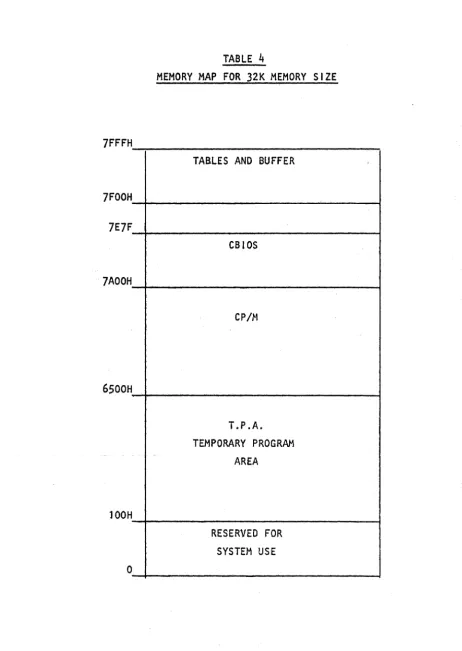
In order to patch a new driver into the CBIOS or modify an existing driver it is necessary to understand the CBIOS memory map
shown in TABLE
4.
Care must be taken not to patch code into anarea that CBIOS uses for buffer storage. In a 32K size system, the
CBIOS can fill the area between 7AOOH and 7EFFH. In REV 2.1 the
area between 7AOOH and 7E64H contains CBIOS code. The area between 7FOOH and 7FFFH is used to store tables and as a buffer used by
the CBIOS. Only the area between 7AOOH and 7E7FH will be loaded
during system boot.
The C810S code can be altered by using DDT. It can be extended
to 7E7FH by this method. It can not be extended past 7E7FH since
code in the area 7E80H to 7FFFH is not saved by DYANGEN. The data
storage area on the system tracks contains only enough space to
save a CBOIOS which extends from 7AOOH to 7E7FH. If it is necessary
to extend the CBtOS beyond 7E7FH then because of a lack of space, this extra code can not be stored on the system track. This extra code can be stored in a special file that is moved into place during system boot.
CP/M REV 2.1
location CCP+7 (for a 32K system this is 6507H). If, for example,
the user wants to add a large driver for the list devices and if
the driver is too large to fit on the system track, then the
following approach might be taken. Assume that the system has a 32K
RAM space. In order to generate space for the extended drive,
generate a 31 K system us i rig MOVCPM 31 ~':. Use the SAVE command to
save this system. The driver will operate in the lK space beyond
the end of the 31K system. That space extends from 7COOH to 7FFFH.
Modify the LIST jump vector at the head of the CBIOS to point to
7COO. Use the Auto-Load feature to load the drive code. For
example, if the driver code is put in a fi Ie called LlST.CON then
the Auto-Load Feature will load and run LIST. The program LIST.COH
should be constructed as shown in the attached I isting of LlST.PRN.
The operation of LIST is described by the comments in the listing.
The step-by-step patch sequence is shown in the following listing
CP/M REV 2.1
5.21 10BYTE
The IOBYTE provides a means of assigning different physical
I/O devices to the CP/M logical devices. Itls function is c;iescribed
in the manual CP/M SYSTEM ALTERATION GUIDE on pages 15 and 16. The
use of STAT to change device assignments is described in the manual
AN INTRODUCTION TO CP/H FEATURES AND FACILITIES on pages 14,15, and
16. REV 2. 1 in it i ali zes the IOBYTE to the va 1 ue 95H. ~og i ca 1
devices to physical device assignment is supported only for the LST: device. The LST: device can be assigned to the CRT:, LPT: or ULI:. The CRT: is the same as the console. The LPT: is the
Ser i a 1 #1 output and ULI: is the Para lle 1 output port. The BAUD
program switches the LST: from Serial 1 to the Parallel Port by
changing the initial value of the IOBYTE to 05H which connects
LST: to UL I : • I n order to extend the use of the I OBYTE, mod i fy
the CSIOS by fol lowing the steps outl ined above.
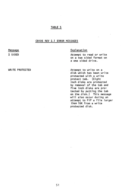
5.22 ERROR MESSAGES
The REV 2.1 CBIOS will generate some new error messages in
addition to those generated by CP/M. These messages are listed
along with an explanation in TABLE
5.
A CP/M operating systemidiosyncrasy causes the WRITE PROTECTED error message to appear
durJngan-attempt .to -2-1Pa-ll1-e1-arge-r.than.l6-K -tram a-write
CP/M REV 2.1
5.3 OPERAT I ON Q[ ~ INTERCONNECTED 5200 ~ 5.;;..,;0_1.;,..0 _
In order to connect a .5200. and a~010. together the following
steps are required.
1. Change the system selection jumper on the main board as
shown in Figure 1.
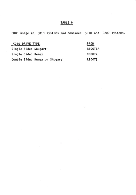
2. If necessary replace the boot strap PROM at locatioh K4 On
the main board with the proper PROM. The proper PROM is determined
by the hardware confJguration of the 501Ol • If the main card shipped
with the .501d. is used thentherewill be no need to change the PROM.
If the main card shipped with the 2200. is used then it may be
nec-essary to change the PROM.' See Table 6 for the correspondence
between PROM type and drive type.
3. Jumpe r the AUX ca rd in the 5200
in,Figure 2.
for BOARD 0 as shown
4.
Remove resistor pack froln location A3 on the AUX card inthe 8/2 system.
5. On the AUX card in the 8/2 system, connect together pin s
7 and 8 of L3.
6. Connect together the 50 pin connectors on the back of the
5200 and the 5010· systems. Make certain that the connecting cable
is not reversed at the ends.
When the system is turned on, it will alternately attempt to
boot on the A drive of the J5200 and the .5010. Insert a system
disk into the drive that you want to become the A drive boot. If,
for example, YOu lrrser't a"dlsK 'into theAd'riiJe6f the '50-1(1:
flien'-when the system boots this drive will be the A drive. The drive
labeled B on the 5010 wi 11 become the B drive. The drive labeled
A on the -520()' wi 11 become the C drive and the drive labeled B on
the 5200 will become the 0 drive. If the system boots on the A
drive of the -5~200the situation is reversed.
CAUTION
IN ORDER TO USE THE COMB I NED 5200 AND 5010 SYSTEM
-lUM~\:R CO~~~c.""\Ot..:)S
(t..oCA.'"t'\OU ')
o
0 .0
•••
•
o
0
0
B
c
JllM pa~
A c. D E. F
Co t-.) II...) eo c:. "T' lO~ ~
5200
0 0
0"-'"
.1
5010
0 0
o • • -1
.J
U t.I\ ?~2. CO~£'c'T ~O·
~1D
D
lL..o<:AT\O~\TABLE 1
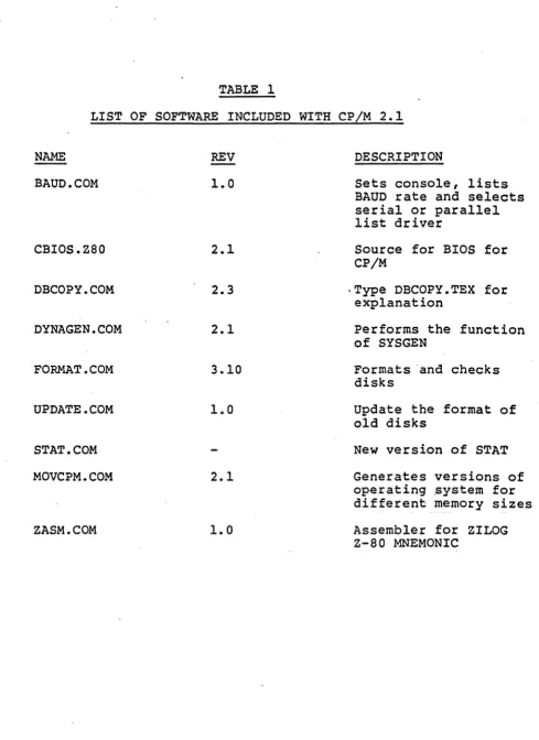
LIST OF SOFTWARE INCLUDED WITH CP/M 2.1
NAME REV
BAUD. COM 1.0
CBIOS.Z80 2.1
DBCOPY.COM 2.3
DYNAGEN.COM 2.1
FORMAT.COM 3.10
UPDATE.COM 1.0
STAT. COM
MOVCPM.COM 2.1
ZASM.COM
1.0
DESCRIPTION
Sets console, lists BAUD rate and selects serial or parallel list driver
Source for BIOS for CP/M
-Type DBCOPY.TEX for explanation
Performs the function of SYSGEN
Formats 'and checks disks
Update the format of old disks
New version of STAT
Generates versions of operating .ystem for different memory sizes
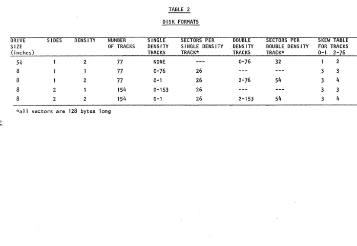
[image:52.613.71.560.61.733.2]TABLE 2
DISK FORMATS
DRIVE SIDES DENS lTV NUMBER SINGLE SECTORS PER DOUBLE SECTORS PER SKEW TABLE
SIZE OF TRACKS DENSITY SINGLE DENS I TV , DENS ITY DOUBLE DENS lTV FOR TRACKS
(j nches) TRACKS TRACK* TRACKS TRACK* 0-1 2-76
5t 2 77 NONE 0-76 32 2
8 1 77 0-76 26 3 3
8 1 2 77 0 ... 1 26 2-76 54 3
4
8 2 154 0-153 26 3 3
8 2 2 154 0-1 26 2-153 54 3 4
,"a 11 sectors are 128 bytes long
~
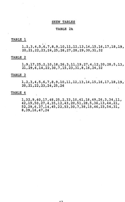
[image:53.797.43.741.65.545.2]SKEW TABLES
TABLE 2A
TABLE 1
1,2,3,4,5,6,7,8,9,10,11,12,13,14,15,16,17,18,19, .20,21,22,23,24,25,26,27,28,29,30,31,32
TABLE 2
1,9,17,25,2,10,18,26,3,11,19,27,4,12,20,28,5,13, 21,29,6,14,22,30,7,15,23,31,8,16,24,32
TABLE 3
1,2,3,4,5,6,7,8,9,10,11,12,13,14,15,16,17,18,19,' 20,21,22,23,24,25,26
TABLE 4
[image:54.615.98.528.62.756.2]5.4 01 SK STORAGE OF DYNABYTE SYSTEMS
This document describes the amount of storage one can expect to
have available on Oynabyte systems. Evaluating the amount of storage
in a system is somewhat akin to trying to make sense out of stereo
system specs. The data, even if accurate, is hard to evaluate since
there are many ways to define the measurements, some more real istic
than others.
The values expressed here for the storage capacity of the Dynabyte
systems reflect two ways of describing the capacity of the systems.
UNFORMATTED CAPACITY is a calculated value based upon the number of
tracks, sectors, and bytes per sector on a diskette. FORMATTED
CAPACITY refers to the amount of space available after the diskette
has been formatted by the DYNABYTE FORMAT program. It is found by
executing the CPIM STAT program. This is perhaps the most realistic
figure to quote when describing disk capacity since it refers to the
actual storage available to the user.
Note that the capacities listed reflect the storage capacities of
common Dynabyte systems; i.e., two floppy drives per system. To figure
the storage on a single diskette, divide the figures by two.
Note also the column marked MEGABYTES. This is a rough
transla-tion of the storage capacity into units that are familiar to many
people. It is just a 'rounded off' way of expressing the same
infor-mation. SYSTEM TYPE 5200 5010 5010 5010-2 5010-2 5012 5012 5012 DRIVE TYPE
5 1/4"
8" 8" 8" 8" CMD CMD CMD UNFORMATTED CAPACITY
631 K
513 K
1064 K
1024 K
2128 K
32579 K
65157 K
97754 K
FOR,"1ATTED CAPACITY
596 K
482 K
1008 K
978 K
2030 K
25760 K
51520 K
77280 K
MEGA-BYTES
NOTES
2/3 QUAD density
1/2 SINGLE density
DOUBLE density
SINGLE density
2
32 (26)
64 (52)
96 (?n
DOUBLE dens i ty
TWO DISKS
THREE DISKS
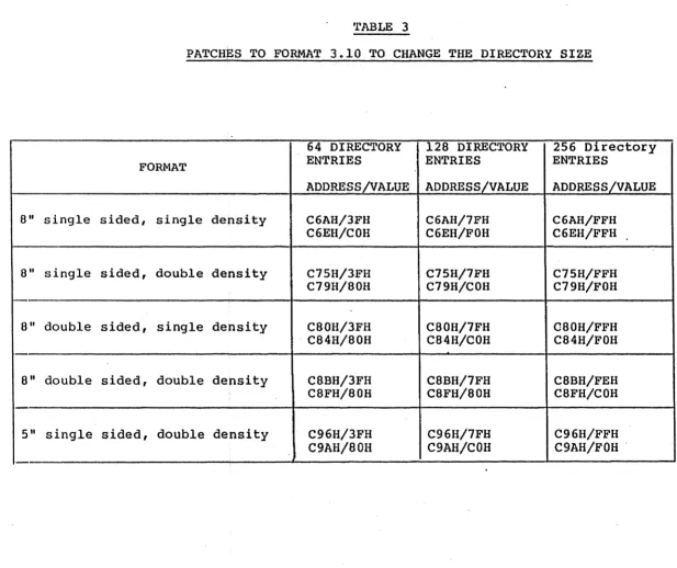
TABLE 3
PATCHES TO FORMAT 3.10 TO CHANGE THE DIRECTORY SIZE
64 DIRECTORY 128 DIRECTORY 256 Directory
FORMAT ENTRIES ENTRIES ENTRIES
ADDRESS/VALUE ADDRESS/VALUE ADDRESS/VALUE
8" single sided, single density C6AH/3FH C6AH/7FH C6AH/FFH
C6EH/COH C6EH/FOH C6EH/FFH
8" single sided, double density C75H/3FH C75H/7FH C75H/FFH
C79H/80H C79H/COH C79H/FOH
8" double sided, single density C80H/3FH C80H/7FH C80H/FFH
[image:56.792.57.674.65.583.2]TABLE 4
MEMORY MAP FOR 32K MEMORY SIZE
7FFFH
TABLES AND BUFFER
7FOOH
7E7F
CBIOS
7AOOH
CP /l-\
6500H
T.P .A. TEMPORARY PROGRAM
AREA
lOOH
RESERVED FOR SYSTEM USE
[image:57.621.52.514.83.734.2]Message
2 SIDED
WRITE PROTECTED
TABLE 5
CBIOS REV 2.1 ERROR MESSAGES
Explanation
Attempt to read or write
on a two 5 i ded format on
a one sided drive.
Attempt to write on a disk which has been write protected with a write
protect tab. (Eight
inch disks are protected by removal of the tab and five inch disks are pro-tected by putting the tab on the disk.) This message will also occur during an
attempt to PIP a file larger
[image:58.615.70.576.23.757.2]TABLE 6
PROM usage in 5010 systems and combined 5010 and 5200 systems.
5010 DRIVE TYPE
Single Sided Shugart
Single Sided Remex
Double Sided Remex or Shugart
PROM RBOOTIA
RBOOT2
[image:59.623.68.536.62.730.2]5.5
THE CCP AUTO-LOAD FEATUREThis note describes the procedure for patching CP/M so that, on BOOT-UP, the system will enter directly into a particular program.
This change eliminates the need for a system user to understand the
operating system. It will keep the user in the applications program
environment. This patch causes the system to return to the specified program on both a cold or warm boot. The patch is made to the CP/M
operating system stored on the outer two tracks of the diskette. To make the patch proceed as follows:
1. First generate a shifted memory image of 1;he CP/M system.
This is done by starting with a diskette that contains the proper
memory size CP/M system on its system tracks.
2. Use DYNAGENto move the system into the computer memory.
Type "DYNAGEN" followed by a carriage return. Respond to the
request "SOURCE DRIVE NAME" with "A" or "BII depending on which drive
the diskette is mounted. Respond to the request "SOURCE ON A,
THEN HIT RETURN" with a carriage return when the source is mounted
on the selected drive. Respond to the request "DESTINATION DRIVE
NAME OR RETURN TO REBOOT" with a carriage return.
3. The system is now in RAM and should be saved by typing
6. Now patch in the command line which you want to execute on boot up. The length (in bytes) of the command line goes into memory
location 987H and the command line its·elf (coded in ASC11) goes into
memory starting at 988H. For example: if you want the system to
directly boot into BASIC and you want BASIC to load and run a program
called MENU. BAS , then the command line would be "BASIC MENU".
This has 11 letters and since 11, decimal is equal to "B" in hexidecimal
then "BII should be stored at location 987H. The letters of the command
string must be converted to ASC11 (for example the letter 8 is equal
to 42H, etc.) The "5" (set) command of DDT is used to set the va lues in memory.
7. After DDT displays the prompt II_II, type 11598711 followed by
a carriage return. The system wi I I respond with 11987 00" and the
cursor will remain positioned after the "0011. Type the length of
the command line (i n the exampe I 11811 ) and hit retu rn. DDT will
then enter this value in memory and display the next memory location.
Enter the desired value (in this case 42) and hit return. Proceed in
this manner to the end of the command. Be sure to type a return
after the last latter so that it is entered into memory. Then type
a period (II.") to exit the set command.
8. Exit DDT by typing a control C.
9. Before doing any other operation place the system, that is
in memory, onto the diskette by using the command "DYNAGENII . Reply
to the request "SOURCE NAME OR RETURN TO SKIP" with a return. Reply
to the request for "DESTINATION DRIVE" with the name (A,8,C or D)
of the drive that contains the diskette that you want to have the
10. When the system reboots, the command wi 11 be executed. If the command. is repeated on the screen followed by a question mark, then it was not successfully executed. This can result if
one of the required files was not found on the disk, If, for
example, BASIC.COM is not present on the disk, then the above example will fail and the system will revert to normal CP/M
5.6
SET,)N
(i. uPA)-DDT L. I ST. HEX
ODT V:':RS 1. 4
i~EXT PC
J?A,G H L..I S r" TO
Ge
THEftPilI vI! tt
co
Dee
010e 0000
-rC:ODE.HEX cooC'.J..It:)( CON7AINS 1:IRtVErt
-R850C ORG- IC~Gl 1-4
NEX"" PC:
011C 0000 -GO
A) SAVE 1 LIST. COM
A:>MOVCPM 31
*
CONSTRUCTING 31K CP/M VER8 1.4
READY FOR "SYSC;EN" OR
u SAVE 36. CF'M31. COM"
A>SAVE 36 CPM21.COM
A:>
CON S 7 eve"" A AI I)
3Jk: SY~TEH1..
CoOe
A)DDT CPM31. COM
DDT VERS 1.4
NEXT PC
:2500 010Cl
-8987
GlP AU7Q - ~oA 1:) 7 0
L.. I $ T. Co ""
0987 ()(;l 4 - I.G/tIG-7'J./ opr CQ~"'~ NO L,., Nt:
0988 20 4C1
09:39 20 49, C L.,"'&::, I'" ~SCI
098A 20 53 r " O)')\~ A ~ g ." ... "
098B 20 54.oJ
098C 20 • I> -1:1987,98(:
0987 04 4C 49 53 54 20 .LIST 4 - - CH~C.k:' PATCH
-A1E8F
lE8F '-'MP
lE92
7COO ~ 'PA7"CJ.I
-.smp
VEC70~ TO POINTN
6w
D~lve~ A'T 'iC"~ ~-GO
A"r
A:>SAVE 36 CF'M31. C~OM - SAVe' 'PATCloIeO
A:>DYNAGEN CPM31.COM
DYNAOEN VERS 2.0
DESTINATION DRIVE NAME (OR RETURN TO
DESTINATION ON A, THEN TyoE RETURN
FUNCTiON COMPLETE
'Pu 7' P
,crr
CIa/ If! DS yS' r~f1f.. 0 N
1:>1 S 1(.
0.000 0000 0000 0000 0000 0000· 0000 0100 0100 0100 0100 0100 0100
0100 11007C
0103 210COl
0106 010004
0109 EDSO
OlOa C9
Oloe O;!.QC
o.
... .,(j '\
OlvJ
0001 0002 0003 0004 0005 0006 0007 0008 0009 0(: (>CO .1
()O12 0013 0014 0015 0016 0017 0018 1)019 0020 0021 0022 0023
;*********************************************************
;***
.
LIST***
;******************"******************"I!'********************
;·
~·
,
·
,
MOVE:·
,
CODE:ORG 100H
LD OE,7COOH LD HL,CODE LD BC,400H LDIR
RET
;THIS MOVES THE.LIST DRIVER
; INTO THE AREA STARTING AT 7COOH
;START OF CODE IN CSIOS ;STARTING LOCATION OF CODE ;MAX LENGTH OF CODE
;MOVE CODE ;GO START CP/M