warwick.ac.uk/lib-publications
Original citation:
He, Wei and Wang, Jihong (2018) Optimal selection of air expansion machine in compressed
air energy storage : a review. Renewable & sustainable energy reviews, 87 . pp.
77-95. doi:
10.1016/j.rser.2018.01.013
Permanent WRAP URL:
http://wrap.warwick.ac.uk/98735
Copyright and reuse:
The Warwick Research Archive Portal (WRAP) makes this work of researchers of the
University of Warwick available open access under the following conditions.
This article is made available under the Attribution-NonCommercial-NoDerivatives 4.0 (CC
BY-NC-ND 4.0) license and may be reused according to the conditions of the license. For
more details see:
http://creativecommons.org/licenses/by-nc-nd/4.0/
A note on versions:
The version presented in WRAP is the published version, or, version of record, and may be
cited as it appears here.
Contents lists available atScienceDirect
Renewable and Sustainable Energy Reviews
journal homepage:www.elsevier.com/locate/rser
Optimal selection of air expansion machine in Compressed Air Energy
Storage: A review
Wei He
a, Jihong Wang
a,b,⁎aSchool of Engineering, University of Warwick, Coventry CV4 7AL, United Kingdom
bSchool of Electrical & Electronic Engineering, Huazhong University of Science & Technology, China
A R T I C L E I N F O
Keywords:
Compressed Air Energy Storage Expander Classification Expander Modelling Optimal Expander Selection
A B S T R A C T
Electrical energy storage has been recognised as an underpinning technology to meet the challenges in the power network arisen from the rapidly increasing penetration of renewable energy. Compressed Air Energy Storage (CAES) has gained substantial worldwide attention in recent years due to its low-cost and high-reliability in the large-scale energy storage systems. Air expander is one of the key components in a CAES system because its operational characteristics determine the power conversion efficiency and the power generation during the discharge period. The performance of the expander contributes heavily to the round trip efficiency of the whole system. This paper presents an up-to-date review of the CAES technology, and methods for modelling and se-lecting expanders for CAES systems. The focuses of sese-lecting the appropriate expansion machines are identifying and analysing the characteristics of both CAES systems and expansion machines, andfinding the matched ex-panders for the CAES system formulation (i.e. diabatic, adiabatic and isothermal CAES) and operational con-ditions (i.e. air pressure, temperature andflow rate). After all, recommendations and guidelines in selecting appropriate expanders and expansion stage numbers are formulated and discussed; this laid a step stone for choosing suitable expansion machines to achieve an overall CAES system high efficiency.
1. Introduction
Carbon dioxide emission, one of the major causes for global warming, has been recognised as a pressing issue and needs to be tackled in this generation[1]. To address this issue, reducing use of fossil fuels is unavoidable, which calls for power generation from re-newable energy sources to meet the electricity demand. It has been evidenced by the rapidly increased penetration of renewable energy to the power network in recent years [2–5]. In 2014, power from re-newable energies represented approximately 58.5% of the net additions to the global power generation capacity, with considerable growths in all regions[6]. By the end of 2014, renewables, mainly wind, solar PV and hydro power, accounted for an estimated 27.7% of the world's power generation capacity, enough to supply 22.8% of global electricity [6]. However, due to the inherent intermittence of the most renewable energy sources, there is a great challenge in the power generation and load balance to maintain the stability and reliability of the power net-work[7]. While various solutions are sought, energy storage has been recognised as one of the feasible technologies to address these issues, which facilitates the power balancing by decoupling the generation and consumption in the time and space domains through multiple charging
and discharging cycles[8].
Based on the form of energy stored in the system, major energy storage technologies include mechanical (pumped hydro, compressed air, andflywheel), electrochemical (batteries), electrical (capacitors), chemical (hydrogen with fuel cells), and thermal energy storage. Technical characteristics of the selected energy storage technologies are listed inTable 1. Mechanical storage systems, has long lifetime, low energy capital cost, and much larger power/energy rating than other energy storage technologies listed inTable 1. Therefore, they are sui-table for time shifting, load shaving, load levelling, and seasonal energy storage. As one of the two large-scale commercialised energy storage technologies, large-scale commercialised Compressed Air Energy Sto-rage (CAES) plants which are able to provide rated power capacity over 100 MW by single generation unit, have demonstrate to be reliable in the large-scale energy management[9].
Because the maturity of Pumped Hydro Energy Storage (PHES), the PHES plants have been deployed worldwide. However, these commer-cialised large-scale plant are subject to severe geographic restrictions. A site for a PHS plant must be suitable for the construction of standing or dammed-up water reservoirs with very large volumes for storing water [10]. In fact, the number of installation of new PHES plants has inclined
https://doi.org/10.1016/j.rser.2018.01.013
Received 22 July 2016; Received in revised form 10 October 2017; Accepted 30 January 2018
⁎Corresponding author at: School of Engineering, University of Warwick, Coventry CV4 7AL, United Kingdom.
E-mail address:Jihong.wang@warwick.ac.uk(J. Wang).
Available online 23 February 2018
1364-0321/ © 2018 The Authors. Published by Elsevier Ltd. This is an open access article under the CC BY-NC-ND license (http://creativecommons.org/licenses/BY-NC-ND/4.0/).
since 90's due to the environmental concerns and the scarcity of fa-vourable sites[11]. The potential for the further major PHES schemes would also be restricted[12]. Different from the PHES plant, in a CAES system, air, instead of water, is compressed and released by com-pressors and expanders to fulfil a cycle of charge and discharge[13]. Although the large-scale storage of the compressed air is also restricted by geologic conditions, there are much more available sites for a large-scale CAES plant than the available sites for PHES. Porous rock servoirs (aquifers or existing depleted gas reservoirs) and cavern re-servoirs (caverns in salt formation and low-permeability hard rock) are appropriate for CAES. For example, existing gas storage facilities for natural gas storage might be suitable for storing compressed air[14].
[image:3.595.39.558.79.182.2]Excluding the successful applications in the large-scale energy sto-rage, with the continuous development of CAES, small-scale systems of CAES are also explored in both academic studies and industrial projects [15–18]. Prototypes of micro-scale and small-scale CAES systems emerged as the alternatives to the electrical or electrochemistry based energy storage technologies, such as batteries[19]and super-capacitors [20]. To compete with the well-developed high energy/power density electrical and electrochemical energy storage technologies as listed in Table 1, small scale CAES systems have several advantages, such as low self-discharge, long life-time, low-maintenance, reliable even in hostile environments, etc. Although there are several published reviews of energy storage systems in which potential benefits of CAES have been recognised[21–24], and a recent overview on CAES history and system classification[25], limited studies were reported on the optimal selec-tion of the CAES system components. Most recently, Marvania and Subudhi presented a comprehensive review of compressed air power engines for vehicles in which the propulsion system is quite similar to CAES[26]. Nevertheless, the power capacity and energy density of the compressed air power engines are limited and significantly smaller than those used in many CAES systems.
In a CAES system, the expander is a critical component in de-termining the rated power output and the overall energy conversion efficiency. The selection of expanders in formulating a CAES system highly depends on both the system operations and the discharge power capacity of the energy storage system[27]. Generally, two main types of expanders can be distinguished from the market: the positive dis-placement (volume) type, such as reciprocating expander, screw and scroll expanders, and the dynamic (velocity) types, such as radial and axial turbines. To select an appropriate expansion machine, several reviews of applications and guidelines of different expansion machines have been reported in the studies of organic Rankine cycle (ORC). Qiu et al. reviewed various expansion machines and discussed the principles of selecting different types of expanders for ORC-based micro-CHP (combined heat and power) systems[28]. Bao and Zhao discussed all types of expansion machines’operating characteristics, aimed to guide the selection of expanders for an efficient ORC system[29]. Lemort et al. compared different expansion machines, especially for the posi-tive displacement types including reciprocating, screw and scroll ex-panders, in ORC systems with different workingfluids[30–34].
Compared to heat engines such as ORC, CAES has its unique
characterisations: 1) air is the workingfluid to fulfil the charge and discharge processes; 2) compared to heat engines which generate electricity between two heat sources, the potential of air, i.e. air pres-sure, plays a much significant role in CAES; and 3) CAES systems charge and discharge associating with multiple heat sources in a variety of ways. Therefore, although the experiences from the design of expanders in traditional heat engine cycles are beneficial, specific considerations and requirements for expander's design are needed for different CAES system types. However, from the published literatures, there is lack of guidelines on selection of expansion machines tofit and match the CAES system formulations. Tofill the knowledge gap and enable op-timal selection and design of expanders in CAES, tools for simulations of a CAES system considering the expanders’ geometric parameters are essential. Rather than general thermodynamic analysis, requirements for a expander model used in CAES system modelling are not only ac-curate sufficiently to present the characteristics of the expander at the component-level, but also efficient in computation and compatible to be integrated to a system-level simulation.
Therefore, this study aims to compare different expansion machines and their potential applications in CAES systems, and review the as-sociated mathematical models which are suitable for a system-level modelling. In order to provide a state-of-the-art picture of CAES tech-nology development and a guideline of selecting appropriate expansion machines in practice, this review covers: 1) an overview of CAES system types, and 2) a comparative discussion of expansion machine types and their applications in CAES systems. For deriving the principles for re-commendations of expanders, classifications of the current CAES sys-tems are introduced. According to the energyflow in a CAES system, three major types of CAES are discussed to form the fundamental principles in choosing appropriate expanders. Then, several machine types of expanders are briefly introduced, including both volumetric and dynamic types. Finally, recommendations of expanders subject to CAES system types and scales are made and a generic preliminary system/component design procedure is also discussed.
2. Overview and comparison of CAES system formulation
In general, a CAES system refers to a process of converting electrical energy to a form of compressed air for energy storage and then it is converted back to electricity when needed. An illustrated conventional CAES system is plotted in Fig. 1. During the charge process, air is pressurised by compressors which are driven by motors using off-peak electricity from the grid or/and renewable energy. Before the storage and the compression, the compressed airflows through interconnected heat exchangers or other heat sinks to decrease its temperature. During the discharge period, the compressed air is first heated by the heat exchangers or other heat sources and produce work by expanders. The mechanical work is converted to electricity by connecting electric generators to the expander's shaft. Five major sub-processes formulate a complete CAES system: 1) air compression; 2) heat exchanges during both charge and discharge; 3) air expansion; 4) compressed air storage in cavity or pressure container/tank; and 5) mechanical transmission Table 1
Characteristics of several energy storage technologies. These characteristics listed in the table are summarised from the review and comparisons in[23].
Characteristics Large-scale CAES Small CAES PHES Li-ion battery Lead acid battery Super-capacity Hydrogen fuel
Power density, W/L 0.5–2 > large-scale CAES 0.5–1.5 1500–10,000 10–400 > 100,000 > 500 Energy density, Wh/L 2–6 > large-scale CAES 0.5–2 200–500 50–90 10–30 500–3000 Rated power rating, MW 100–1000 0.003–3 potential to 10 100–5000 0–100 0–40 0–0.3+ < 50 Rated energy capacity, MWh < 1000 < ~ 0.01 500–8000 0–10 0–40 0–0.0005 0.312 and 39
Lifetime, year 20–40 > 23 40–60 5–16 5–15 10–30 5–20
Cycle efficiency 40–70% – 70–85% 75–97% 63–90% 84–95% 20–66%
between motor, generator, compressor, and expander.
Depending on the scale of a CAES system, it can be roughly divided into large-scale CAES (> 100 MW), micro-scale CAES (tens of kW) and small-scale CAES ranged in between. Large-scale CAES systems are normally built for grid applications in load shifting, peak shaving, and frequency/voltage control [21]. Small-scale CAESs are more suitable for integration with renewable energy for back-up, load following and uninterruptible power supply. An application of small-scale CAES system for load following was presented in[35]in which an approach of investigating and controlling was also used to minimise the specific compression work. Micro-scale CAES is capable to be used in a multi-purpose system. A good example of a micro-scale CAES combines en-ergy storage, air cycle heating and cooling was analysed in[36]. Proper types of expansion machines suit different CAES system scales and operations. High performance of these systems is only achieved when appropriate compressors and expanders are selected. As a matter of fact, overall performance of a CAES system is significantly affected by the efficiencies of air compression and expansion processes, because they are the“interfaces”to transfer different energies where significant exergy loss normally occurs. In a cycle from the charge to the discharge, more stages of the compression and expansion processes are used, more sensitive are the compressor's and expander's efficiencies to the overall round trip efficiency. It was demonstrated that the isentropic effi-ciencies of compressors and expanders/turbines are the two most in-fluential parameters impacting the overall CAES performance[37].
Depending on trajectories of air compression and expansion from state 1–5 as shown inFig. 1, CAES can be mainly divided into three categories: conventional diabatic CAES (D-CAES), adiabatic CAES (A-CAES), and isothermal CAES (I-CAES). An illustration of these three CAES systems are shown inFig. 2in which States 1–5 present initial air, compressed air, stored air, discharged air and exhaust air as illustrated inFig. 1. D-CAES, A-CAES and I-CAES are illustrated inFig. 2(a)–(c), respectively.
2.1. Diabatic compressed air energy storage
Conventional D-CAES can be considered as a CAES assisted gas turbine cycle. Therefore, similar to conventional thermal power plant applying Brayton cycle, the performance of the plant is determined by its thermal efficiency. The intrinsic nature of heat engines indicates that an increase in the temperature differences between the heat sources directly enhances the thermal efficiency of the cycle. However, in a D-CAES, excluding heat generated by combustion as a portion of energy input, off-peak electricity, another part of energy input, is also con-verted into the energy potential of compressed air which is stored in the cavern and released at the peak-period. As shown inFig. 2(a), because of the heat produced by combustion (Qin), temperature of the air from the state 3 which is the compressed air stored is significantly increased to the state 4. Consequently, more work can be generated in the ex-pansion process from the state 4 to the state 5 compared to the stand-alone Brayton cycle.
[image:4.595.137.459.53.198.2]Until now there are two CAES plants in operation in the world. The first utility-scale CAES project is the 290 MW (upgraded to 321 MW) Huntorf plant in Germany using salt dome, which was built in 1978. The other is a 110 MW plant with a capacity of 26 h in McIntosh, Alabama. These traditional D-CAES systems have been demonstrated to be successfully operated in realistic for several decades. The Huntorf CAES plant has reliably operated with excellent performance with 90% availability and 99% starting reliability for the last 30 years and still in good condition [38]. McIntosh CAES plant also has maintained an average starting reliability of between 91.2% and 92.1%, and an average running reliability of 96.8% and 99.5% for discharge and charge periods respectively[38]. At present, several CAES plants are being constructed or projected to be constructing worldwide. For ex-ample, a 300 MW CAES installation using a saline porous rock forma-tion being developed near Bakersfield in California and another 150 MW salt-based CAES is also being developed in Watkins Glen, New York [39]. However, D-CAES has some disadvantages such as con-siderate thermal losses, dependence of fossil fuel and requirement of Fig. 1.Schematic diagram of a conventional CAES.
[image:4.595.85.511.607.729.2]geological formations.
To overcome these disadvantages, some improvements have been made to increase the performance of D-CAES. In McIntosh CAES plant, thermal energy of the exhausted gas is recovered using Recuperator to increase the temperature of the compressed air beforeflowing to the high-pressure turbine. Accordingly, it reduces one-quarter of fuel con-sumption and leads to the round trip efficiency enhancement[40]. The round trip efficiencies of the CAES plants are around 54% in McIntosh, higher than 42% in Huntorf[22]. Additionally, other thermal energy recovery methods are also applied in the D-CAES system. It was re-ported that energy efficiency of a 100 MWe D-CAES can be increased from 48% to 86% by integrating a 105 MW thermal energy storage (TES) which was connected to a distinct heat network[41].
2.2. Adiabatic compressed air energy storage
Moreover, to eliminate the dependence on fossil fuels without a sacrifice of the performance of CAES, A-CAES is proposed. A-CAES systems use TES to recover and store the air compression heat during the compression process and reuses it at the expansion stage. As shown inFig. 2(b), heat released from the state 2 to the state 3 is stored in TES and reused to increase the temperature of the air from the state 3 to the state 4. Compared to a D-CAES system, the energy input of A-CAES is only off-peak/renewable electricity. Thus, the round trip efficiency, which is the ratio of the electricity output during the discharge to the sole electricity input for the charging, is a key performance to evaluate an A-CAES system. In fact, in an A-CAES system, the off-peak electricity is stored in two forms, namely pressure of the compressed air and heat stored in the TES. Consequently, the storage and conversion efficiencies of both forms determine the round trip efficiency of the entire A-CAES system.
Efficiency of an A-CAES is expected to achieve 70–75%[23,42–44]. However, there is no commercially commissioned plants or projects that have demonstrated the expected efficiency until now. The perfor-mance of A-CAES varies with different designs. For instance, Grazzini and Milazzo reported an efficiency of 72% in a 16,500 MJ A-CAES system with variable configuration[44]. Garrison and Webber pro-posed a system using the A-CAES system that was driven by wind en-ergy and concentrating solar power (CSP), and calculated the overall energy efficiency 46% for the CAES sub-system[45]. Using the ejector technology, performance of an A-CAES was improved by recovering the pressure loss. In the A-CAES system with an ejector, the system power output was increased from 31.10 MW to 32.81 MW and the round trip efficiency was improved from 61.95% to 65.36%[46]. Minutillo et al. used an small-scale A-CAES unit and a photovoltaic (PV) power system to supply a small-scale off-grid base transceiver station, in which the adiabatic operation was achieved by a TES unit to cool and reheat the air [47]. The efficiency of the small-scale A-CAES was reported to be > 50% [47]. ADELE project, an A-CAES system for electricity supply, undertaken by RWE Energy, expected to have an efficiency around 70%[48]. In China, Institute of Engineering Thermophysics, Chinese Academy of Science has built a 1.5 MW A-CAES pilot plant and constructing a 10 WM A-CAES pilot system, and relevant studies of the realistic performance of A-CAES are ongoing[49].
In fact, overall performance of an A-CAES is influenced by many factors from the charge to the discharge. Ke et al. studied the effec-tiveness and pressure loss of heat exchangers in A-CAES systems and found that the system efficiency of A-CAES can be significantly im-proved by increasing heat exchanger effectiveness either in the charge process or the discharge process [50]. Through analysing different CAES configurations, Hartmann et al. concluded that the key element to improve the efficiency of A-CAES is to develop high-temperature thermal storage (> 600 °C) and temperature resistant materials for compressors[51]. Barbour et al. proposed an A-CAES system based on direct contact packed beds as TES and suggested that an overall effi -ciency in excess of 70% is achievable[52]. In contrast, Wolf and Budt
proposed a low-temperature A-CAES plant using multi-stage radial compressors and expanders, in which the temperature of the hot TES was 95–200 °C[53]. Although the proposed low-temperature A-CAES showed a slightly decreased round trip efficiency in the range of 52–60%, advantages of fast start-up characteristics and wide-ranging partial load ability were achieved[53]. Luo et al. carried out an ex-amination of the potential system efficiency improvement using low-temperature TES in an A-CAES[37]. It indicated that the cycle effi-ciency and heat energy cycle efficiency of the designed low-tempera-ture A-CAES systems can reach around 68% and 60%, respectively[37].
2.3. Isothermal compressed air energy storage
I-CAES is similar to Ericsson Cycle, and expected to have the highest round trip efficiency. In an I-CAES, the maintained temperature during the compression and expansion is capably achieved by the sufficient heat transfer using moisture in air or two-phaseflow of air and droplets. The isothermal or quasi-isothermal process, therefore, leads to the least amount of thermodynamic work in compression and the maximum work of expansion. Kim and Favrat presented energy and exergy ana-lysis of different types of micro I-CAES and A-CAES systems[54]. It indicated that quasi-isothermal compression and expansion processes are more preferable than adiabatic compression and expansion, espe-cially for applications with high pressure ratios[54]. Excluding studies of the conventional volumetric expanders to achieve isothermal or quasi-isothermal compression and expansion[55–59], a concept of li-quid piston whose structure is similar to reciprocating machines was proposed to improve the reversibility of gas compression and expansion [60]. The proposed liquid piston utilised a column of liquid to compress or expand gas in afixed volume chamber, which is capable of max-imising the surface area to volume ratio in the gas chamber, minmax-imising the thermal dissipation, and creating the near-isothermal operation. The liquid piston was also reported to have no gas leakage, replacing the seal friction with viscous friction, and inherent thermal medium to carry and store heat[60].
To improve the isothermal operation for CAES, drop spray injection heat transfer was introduced and combined with the liquid piston[61]. Park et al. carried out an experimental analysis of the liquid piston for an ocean CAES prototype and demonstrated that heat transfer char-acteristics of the liquid piston compression were effective in reducing the air temperature and maintaining a near isothermal operation[62]. Saadat et al. also presented a novel I-CAES using the liquid piston for wind turbines[63]. Yan et al. carried out an experimental study on porous inserts of a liquid piston based I-CAES which had the pressure ratio of 10 for compression and 6 for expansion[64]. Besides using the liquid piston, moreover, enhancement of the heat transfer to maintain the isothermal compression and expansion is also achieved by injecting water spray or droplet into the airflow. SustainX used a mechanical link powering a two-stage, mixed-phase (water-in-air) heat transfer process within pneumatic cylinders[65]. The I-CAES power unit pro-vided both isothermal compression and expansion. Another company, LightSail Energy, developed an I-CAES system by injecting afine, dense mist of water spray which rapidly absorbs the heat energy of com-pression and uses it in expansion to maintain the constant temperature during the charge and discharge periods using reciprocating machines [66]. In addition to the reciprocating type of machines, studies of other types of machines to achieve isothermal or near isothermal compres-sion/expansion are also found in literatures, such as screw[67]and scroll[68].
2.4. Operating conditions of D-CAES, A-CAES and I-CAES
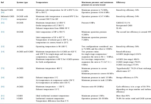
independent of the maximum operating temperature and storage tem-perature[53]. The reported CAES systems, with their operation con-ditions and key parameters are listed inTable 2. As shown inTable 2, the highest operation temperature is found in D-CAES systems. In practice, the limiting temperature in D-CAES is restricted by the current development of compressors and expanders. Because of the availability of the proven gas turbine trains operating on a pressure drop of 11–1 bar, the air temperature at the inlet of the LP (low pressure) tur-bine can be as high as more than 800 °C[53]. Due to the high pressure drop of 42–11 bar of present HP (high pressure) gas turbines, D-CAES such as Huntorf plant, designed the HP turbine on“steam turbine en-gineering”practice[53]. As a result, the inlet temperature of the HP turbine is only 550 °C which is a common feature of current steam turbine operation. Detailed operational information of these two plants, Huntorf and McIntosh, can be found in[69].
In contrast, through the listed A-CAES system performance, it can be found a wide range of operating temperature, which is from 150 to 650 °C, approximately. The upper limit of the operational temperature is usually restricted by the availability and performance of high-tem-perature TES at present[70]. Taking advantages of the rapid develop-ment of the TES, especially the high-temperature TES, operating tem-perature is predicted to be increased. Until now, selections of the operating temperature and types of TES vary among different applica-tions and groups. A reported project, the AA-CAES Project, is comprised of 19 different partners, considered a full range of thermal storage devices, including phase-change, high heat capacity solid and liquid media and hybrid systems. The project selected a range of solid media (natural stone, concrete,fireproof material and metal) as TES due to the advantages of high surface area for heat transfer and low cost of the
storage materials[71]. But they also pointed out that expensive pres-surised containers are required for solid TES[71]. Liu and Wang carried out a sensitive analysis of the heated temperature of the compressed air at the inlet of the HP turbines in the range from 490 K to 580 K using thermal oil as the sensible TES medium[72]. They found increased round trip efficiency and improved total exergy efficiency of the A-CAES[72]. Yang et al. summarised several sensible heat storage ma-terials from literatures [73,74] and proposed a modified A-CAES system. They called the system hybrid thermal-compressed air energy storage using wind power, which further increased the temperature of heat storage (potential maximum temperature of TES was as high as 1273 K in their theoretical analysis)[75].
Compared to A-CAES integrated with the sensible TES, there is a limited number of published works of A-CAES using latent TES. Recently, Peng et al. studied an A-CAES incorporating Packed Bed Thermal Energy Storage (PBTES)filled with PCM particles[76]. Also, hybrid sensible/latent TES was proposed in the A-CAES systems using packed bed of rocks with encapsulated PCM on the top, in which the stored temperature was as high as 600 °C[77]. PBTES storing heat with sensible (solid particles) or/and latent heat (PCMs) is a promising and attractive method[78]. It has been investigated in solar thermal energy systems and energy saving buildings [79–81]. Tian and Zhao sum-marised and listed several commercial PCMs, inorganic salts and eu-tectics based on[82,83], which were listed in[84]. The phase change temperatures of these materials are ranged from 100 °C to 897 °C, and the latent heat is ranged from 124 to 560 kJ/kg. Therefore, the ap-propriate operational temperature of PCM shows the possibility of using the latent heat TES in the A-CAES systems in future.
[image:6.595.41.537.81.423.2]In addition, the high energy density of latent heat storage will Table 2
Some CAES systems from literatures.[55,56,63,65,77,91–97].
Ref System type Temperature Maximum pressure and minimum
pressure in cavern/vessel
Efficiency
Huntorf CAES D-CAES Maximum inlet temperature for LP is 850 °C, for HP is 550 °C
Maximum pressure is 7.2 MPa, Round trip efficiency 42%
[89] Operation pressure 4.8–6.6 MPa
McIntosh CAES D-CAES with recuperator
Maximum inlet temperature is around 870 °C for LP, around 540 °C for HP
Operation pressure 4.5–7.4 MPa Round trip efficiency 54%
[73,91]
[92] D-CAES Maximum temperature is 1050 °C Pressure 6 MPa CAES-CC 51.1% Outlet temperature of LT 583 °C Recuperated CAES
Exhaust temperature from HRSG 95 °C 53.4%
[93] D-CAES Inlet temperature of HP is 550 °C Minimum operation pressure 4.2 MPa
The second law efficiency is around 45%
Inlet temperature of LP is 827 °C Maximum operation pressure 7.2 MPa
Temperature of exhaust gas is 204 °C, Air temperature in cavern/vessel is 25 °C
[53] A-CAES Operating temperature is 90–200 °C Two configurations considered: one is 7.2 MPa and the other is 15 MPa
Round trip efficiency 56%
[54] A-CAES and I-CAES Maximum temperatures for A-CAES are 623 °C and 239 °C for single-stage and two-stage compression, respectively;
Two pressure ratios: Round efficiency: for single stage compression/
expansion the ratio is 50 (~ 5 MPa);
A-CAES (single-stage) 23.6%
Maximum temperature is 80 °C for I-CAES systems for both configurations
for two-stage compression/ expansion the ratio is 7.1 & 7.1 (~ 5 MPa)
A-CAES (two-stage) 48.6% I-CAES (single-stage) 70.6% I-CAES (two-stage) 73.9%
[75] A-CAES Maximum temperature 400 °C Maximum pressure in cavern 6.6 MPa
“hypothetically”79.2% if heat exchanger effectiveness 0.7
Minimum pressure in cavern 4.6 MPa
[94] A-CAES Exhaust temperature 3 °C Maximum pressure in tank 3.5 MPa Storage efficiency is 57% Air temperature at compressor outlet 159 °C Minimum pressure in tank 2.5 MPa
Air temperature at turbine inlet 130 °C
[95] A-CAES Maximum temperature ~ 150 °C Pressure ratio 90 (9 MPa) Cycle efficiency is in a rage of 50–75% depending on stage number and turbine efficiency
Exhaust temperature 15 °C
[61] I-CAES Ideal isothermal constant temperature Maximum pressure 1 MPa More than 90%
reduce the required volume for storing certain amount of heat in an A-CAES system. The behaviour of near isothermal heat transfer of the appropriate PCMs during the phase change period is capable of sig-nificantly enhancing the heat transfer and optimally controlling the air temperature. Studies of PBTES with a cascade of PCMfilling[85] fur-ther indicated the potential performance improvements with optimal PCMs-fillings in terms of selections and combinations of the different materials. However, PCMs usually have low thermal conductivities which needs to be improved by heat transfer enhancement technologies or new composite PCMs. For thermochemical TES, currently, there is no integration with A-CAES found in the survey of published literatures.
Moreover, as so called isothermal CAES, operational temperature from the charge to the discharge is supposed to be maintained con-stantly. However, due to the difficulties to achieve the isothermal compression and expansion processes, I-CAES systems are often oper-ated at a near-isothermal operation. Slight temperature increases and decreases occur in the compression and expansion, respectively. From literatures, several operating pressures and temperatures are found in different experimental or/and theoretical I-CAES systems, which are shown inTable 2. Park et al. carried out a numerical analysis of a quasi-isothermal thermodynamic cycle for an underwater CAES and indicated only 26.6° increase of thefinal mean temperature with the air pressure increases to 25 bar[86]. In fact, Yan pointed out that a shorter com-pression/expansion time leads to a higher temperature rise and more close to the adiabatic process[87]. To overcome the trade-off, porous media inserts have been used to improve the heat transfer without the sacrifice of power density and thermal efficiency of I-CAES systems [88]. According to the computational results, the metal foam kept the bulk temperature below 360 K if it occupied the full chamber length (575 K for adiabatic as a reference)[88]. Also porous inserts increased power density by 39-fold at 95% efficiency and enhanced efficiency by 18% at 100 kW/m3power density in compression; in expansion, power
density was increased three-fold at 89% efficiency and efficiency was increased by 7% at 150 kW/m3power density[64].
Apart from the operating temperature, operating pressures are slightly different for the three CAES systems as well. In a traditional D-CAES system, according to the integration of the gas turbine cycle and large volume of the cavern, the pressure of the compressed air can be adjusted to an appropriate value to meet the energy and power re-quirements during the charge and discharge periods. Conversely, be-cause both A-CAES and I-CAES are usually used in the small-scale or micro-scale energy storage systems, such as the integrated CAES and wind turbine or other distributed energy generations, to achieve a high energy density of the storage and downsize the paired electrical com-ponents, high pressure of the compressed air is usually applied.
2.5. Further discussion of D-CAES, A-CAES and I-CAES systems
For choosing an appropriate system type, the functionality of the system determines the system type (i.e. D-CAES, A-CAES and I-CAES) and detailed configurations/specifications, such as the system rated power and energy capacity. The D-CAES and A-CAES systems are sui-table for grid-scale energy storage applications (~ 100 WM and ~ 1000 MWh), and a small CAES system may choose the system type between A-CAES and I-CAES. Among the three system types, D-CAES systems have the highest degree of technology maturity and the lowest capital cost. However, D-CAES systems utilise fossil fuels in the op-eration and have emissions of carbon dioxide, nitrogen oxides, and sulphur dioxide. Nevertheless, D-CAES is still regarded as an energy storage technology with low environmental impact in general [96]. Depending on the local policies, potential penalties for these emissions will increase the lifecycle cost of the D-CAES systems. A-CAES and I-CAES systems have no burning fossil fuels involved and its realisation highly depends on efficient system configuration and expanders. A-CAES and I-A-CAES is still at the stage of pre-commercialization, so both the expected technical performance of the system and the
cost-effectiveness need to be demonstrated.
High degree of reliability and stability of the system performance are the basic requirements for achieving the cost-effectiveness in a life cycle. With the operational data over decades, traditional large-scale D-CAES system has demonstrated its very high storage reliability and running reliability in both charging and discharging periods. Different from D-CAES, the reliability of novel A-CAES and I-CAES systems also depends on the performance of the heat storage and heat transfer ef-fectiveness. High exergy capacity and low exergy loss of both the heat and gas storages are essential for these advanced CAES-TES systems.
Lifecycle economic cost of CAES is another crucial factor in de-termining the system selection. For grid-connected energy storage ap-plications, as pointed by Budt et al., economic aspects are significantly determined by country-specific and short-term changing market con-ditions, and the political and regulatory framework[25]. For the off-grid micro-off-grid systems, the capital cost and the maintenance cost of CAES define the payback time of the systems. A cost-effective off-grid CAES system usually refers to a scenario in which the cost of the CAES system is comparable to other technology solutions. Because CAES systems have negligible maintenance cost, capital cost of the system dominate the life-time cost. Although the capital cost of a large-scale CAES system is usually high, the long lifetime and very little waste materials from the CAES system significantly decrease the detrimental effect of the high capital cost and result in a reduction of the system lifecycle cost. A major portion of the capital cost in these CAES systems is the high-pressure containment cost. White et al. assumed that the containment cost is proportional to the product of pressure, internal volume [97]. This pressure dependant containment cost governs the cost of vessel-based gas storage in all system types and high-pressure heat reservoirs used in A-CAES systems. Currently, Lightsail are trying to significantly reduce the cost by constructing the advanced carbon fibre tanks rather than using steel pressure vessels[98].
2.6. Other categories of CAES
Besides the classification of D-CAES, A-CAES and I-CAES, several novel CAES systems are also proposed in recent years, such as com-pressed air storage with humidification (CASH), underwater CAES (UWCAES), liquid air energy storage (LAES), and supercritical CAES (SC-CAES). In addition, replacing air with carbon dioxide, liquid carbon dioxide energy storage (LCES) are also found in literatures.
CASH is a gas turbine power plant based D-CAES combining air saturation to boost power and improve performance. A saturator is added in D-CAES and humidification is utilised to increase water va-pour in the airflow. Because of the water vapour existing in the air, the recovery of waste heat which is used to heat up the mixture of air and water vapour results in an increase of up to 30% in energy per unit mass flow through the turbine without additional fuel and further compres-sion[99]. In addition to efficiency increasing, emission of NOx for-mation is reduced due to the reduced combustion temperature [99]. Zhao et al. proposed a similar ideal that integrated the humid air tur-bine (HAT) cycle with D-CAES and built a comtur-bined heat and power system[100]. The power output of expansion train of the CAES-HAT was improved by about 26% compared to conventional D-CAES at the design operation[100].
[101,102]. Based on the type of storage vessel used in UWCAES, two categories are classed: rigid vessels such as submerged caissons an-chored to the seabed, and cable-reinforced fabric bags anan-chored to the seabed, usually known as Energy Bags [13]. Both approaches were studied respectively by different research groups worldwide [13,103–105].
LAES has very high energy density by storing compressed air in the liquid state, around 20 times higher than a normal CAES plant[106]. Usually LAES is suffered by low cycle efficiency which motivated the research for performance improvements. Several LAES systems are proposed and described by Ameel et al.[106]. The work showed that the cycle efficiency of the ideal Linde refrigeration and Rankine cycle to store liquefied air was 36.8% and 43.3% in the combined cycle using waste heat at 300 K Morgan et al. described a novel LAES by recycling and storing thermal energy between the charge and discharge pro-cesses, with 45% efficiency from a low grade heat to power [107]. Guizzi et al. also developed a study to assess the efficiency of LAES and indicated the obtainable round-trip efficiency in the range of 54–55% [108]. A LAES pilot plant (350 kW/2.5 MWh) has been built at Slough Heat and Power plant in London UK and a further scaled-up LAES pilot plant (5 MW/15 MWh) is being constructed in Manchester UK[109].
Alternatively, to increase the overall efficiency of CAES using li-quefied air, SC-CAES is proposed recently. Without restrictions of cur-rent air liquefaction technologies, SC-CAES achieves a high overall ef-ficiency due to advantageous properties of supercritical air[110]. In SC-CAES, compressed air is stored in the liquid state. The efficiency of SC-CAES can reach 67.41% and the energy density can reach 3.45 × 10⁵kJ/m3, which is approximately 18 times larger than that of
conventional CAES[110].
Rather than using air in LAES and SC-CAES, LCES uses carbon di-oxide as workingfluid to store energy in the liquid state. Compared to liquid air, carbon dioxide as workingfluid has the advantages of high critical temperature and a susceptibility to liquefaction[111], which gives a flexibility in selecting material for cryogenic energy storage. Thermodynamic analysis of three energy storage systems using liquid carbon dioxide indicates the cycle efficiency in a range of 40–57% and energy density of approximately 36.061 kWh/m3[111].
3. Expanders: working principle, modelling approach and machine selection
Expander, in general, operates in a reverse process of the same type compressor. Various types of compressors are used in a wide range of applications, from fridges to rocket engines. These compressors have significant impacts on the prototypes of expanders. For compression and expansion, one is a reverse process of another, so key principles in design are shared between these two machines. Positive displacement machine mainly includes reciprocating type and rotary type in which screw and scroll are two of major expander types. In addition, dynamic machine is majorly divided into axial type and radial expander type. The positive displacement expanders are operated in an intermittent mode which is cyclic in nature. Conversely, dynamic expanders are operated continuously without interruption of theflow at any point in the expansion. Compared to expanders, as mentioned earlier, com-pressors are well developed and far more investigated. Typical opera-tion ranges of these types of compressors are illustrated inFig. 3, which are determined by their unique designs. Because of the similar design in geometry of expanders in the same type, these characterisations of performance can be considered to approximately characterise the same type of expanders in general.
3.1. Thermodynamic analysis and modelling of expansion process
Conventionally, thermodynamic analysis and modelling of a CAES is usually based on general compression and expansion process with ideal gas theory. The mechanical work of an expander is converted from
energy change of compressed air. In accordance to the different ex-pansion trajectories, enthalpy changes of air varies in different CAES system types. In both D-CAES and A-CAES, the expansion can be con-sidered as isentropic processes without the heat transfer with external environment, or polytropic expansion when the heat transfer is con-sidered with the environment. But expansions occurred in these two CAES processes have different initial conditions of the compressed air because of different inter-stage cooling and heating processes. Moreover, the isothermal expansion is maintained in an I-CAES system. In thermodynamics, although these expansion processes are dif-ferent, based on thefirst law of thermodynamics, expansions of ideal gas apply a general relation which is
=
pvn const (1)
wherenis an index which is varied among these processes:n=0for isobaric process, n=1 for isothermal process, n=κ for isentropic process, and1<n<κorn>κfor polytropic process.pis pressure of air, andvis specific volume.
The air enthalpy variations depends on the air expansion paths in expanders. The reversible specific isentropic expansion work of air can be expressed as,
∫
= =
− −
−
h νdp κ
κ R T
p
p
Δ
1 [( ) 1]
s in
out s out s
in κ
κ ,
1 ,
1
(2)
where in and out present the initial andfinal state of the expansion, s presents isentropic process.Tis temperature andRis gas constant,his enthalpy.κis the specific heat ratio. If the ideal gas equation presents air,
=
pv R T (3)
The temperature at the outlet of expander after the isentropic ex-pansion can be also obtained,
= −
T T p
p
( )
out s in out s
in κ
κ ,
, 1
(4)
Additionally, according to the definition of polytropic efficiency,
ηp
exp, and the characteristics of polytropic process, the decrease of
spe-cific gas enthalpy during a polytropic expansion can be obtained
∫
= =
− −
−
h η νdp η n
n R T
p
p
Δ
1 [( ) 1]
p p in
out p p
in out p
in n
n exp
,
exp
, 1
(5)
where superscript p presents polytropic process. The temperature at the outlet of the expander in a polytropic process is obtained replacingκby
nin Eq.(4).
[image:8.595.324.543.51.206.2]Applyingn=1in Eq.(1)and ideal gas equation as shown in Eq.(3), the change of specific air enthalpy from inlet to outlet in an isothermal expander can be presented as
∫
= =
h νdp R T ln p
p
Δ t ( )
in
out t out t
in ,
1 ,
(6)
where t presents isothermal process.
Although air is usually treated as an ideal gas and this assumption has been widely used in analyses of CAES systems[37,51], realistic gas models increase the accuracy of predicting the expansion work and enthalpy change of air expansion through the expander in a CAES process. Budt et al. discussed effects of the real gas properties of air in CAES systems[25]. They used isobaric capacity as an example and il-lustrated how the real gas properties affecting the performance of an A-CAES system. The deviations of isobaric capacity between ideal and real gas models increase with an increase of pressure and decrease with a decrease of temperature. It indicated that the real gas behaves much differently as compare to ideal gas if the air is cooling down at a high pressure[25]. In addition, because water is actually contained in the ambient air, and water vapour might be injected into compressed air to increase the system efficiency (e.g. CASH); humid air is the working fluid of these CAES systems. Condensation of water vapour may occur during the inter-cooling in heat exchangers orflowing through TES, and appropriate real gas models of humid air should account for these be-haviours, especially in high-pressure CAES systems. To this end, for purpose of more accurate predictions, a number of empirical correla-tionsfitting experimental data of dry/humid air[113–117], have been implemented in the modelling to present the real gas effects. Software using these real gas models are also available, such as REFPROP[118] and CoolProp[119].
Compared to the general thermodynamic analysis, accuracy of the modelling can be significantly improved by considering the specific geometric design of expanders. Models of these expanders are im-portant to characterise their operations and performance. These models are mainly classed into empirical, semi-empirical and geometry-based models. Empirical models are those purely derived based on experi-mental data. They are usually in algebraic expressions to present spe-cific expander characteristics. These models can be easily evaluated without using iterative numerical methods. Therefore, empirical models are widely used in dynamic modelling at the system-level be-cause of the low computations. Nonetheless, the parameters and ex-pressions in the models are lacking physical meanings and only vali-dated for restricted designs and operations. Additionally, semi-empirical models are developed. On one hand, these models usually consider the whole physical process of an expander through the inlet to the outlet. On the other hand, these models also involve parameters fitted by experimental data, such as energy losses. With the enhanced modelling accuracy, simulations using the semi-empirical models are slower than the empirical ones but still sufficiently fast to be integrated at the system-level.
In addition to empirical and semi-empirical models, geometry-based models, also called deterministic models, are based on geometric parameters of the expanders. Mathematical descriptions are developed on the basis of conservation laws of mass, momentum and energy to trackflow changes through the expansion process including heat and mass (e.g. leakage) transfer. Fully resolved model in space refers to the computational fluid dynamics (CFD) which is a robust and powerful tool that accurately simulates the performance of expanders. However, compared to empirical models and semi-empirical models, computation of CFD modelling is extremely intensive, which takes much longer computation time. Therefore, they are primarily suited for analysis and optimisation of a well-designed expander, and not appropriate for dy-namic simulations of expander over a range of operations at the system-level. To reduce the computational burden of geometry-based model, three dimensional models are simplified into one dimensional model with the averaged flow properties. These geometry-based semi-em-pirical models, therefore, are often used for the system-level modelling.
3.2. Reciprocating machine
The use of reciprocating machines as compressors/expanders is the patriarch of the family. The reciprocating compressor has a longest history in compressor development with wide applications ranging from households to industries. In general, the reciprocating machine is a volume-variation based, intermittentflow machine. The machine uses the reciprocating movement of piston within a cylinder to actuate gas from one pressure level to another (as shown in Fig. 4). The main component of a reciprocating machine consists of frame, crankshaft, crosshead, distance piece, piston rod, piston, cylinder, and valves. In a reciprocating expander, the compressed gasflows into the intake valve, and enters the cylinder where it is expanded by a reciprocating piston via a crankshaft. Gas is then discharged through the discharge valve. The potential energy of the compressed gas is transferred to mechanical energy of the shaft. In the expander, the timings of opening and closing the intake and exhaust valves can be controlled. For example, the intake valve of the expander opens when air reaches sufficient pressure in the cylinder. The air overcome the combinedflow resistance of the valve spring load and the downstream pressure.
Reciprocating expander has lowflow rate and high pressure ratio. The rotational speed is usually lower than that of rotary expanders, which is possible to avoid using speed reduction gearbox and the ex-pander can be directly attached to the generator. Its isentropic effi-ciency is capable of being as high as 76%[121]but efficiencies less than 50% are also found[122]. For CAES systems, reciprocating ex-panders are appropriate for micro-scale and small-scale systems. In these scaled-down CAES systems, especially for micro-scale systems, because of the low storage capacity and lowflow rate, relatively high pressures are usually necessary to increase the energy and power den-sity. Reciprocating expanders are suitable for meeting these require-ments in scaled-down CAES systems due to the high internal volume ratio that ranges from 6 to 14[34].
[image:9.595.335.522.57.278.2]Inheriting mature technologies from reciprocating compressors, reciprocating expanders can be directly modified and manufactured. The reciprocating expander, or piston expander, has been an interest in the 1970s with the development of car steam engines [123]. A re-ciprocating expander was studied in automatic waste heat recovery, tested in pressure ratios from 20 to 40, rotation speeds from 500 to 6000 rpm and up to 6 kW power output[124]. Wronski et al. optimised operations of a reciprocating expander for a medium-temperature heat source in an ORC system by controlling the condenser temperature and
the cut-offangle[125]. They found an isentropic efficiency approxi-mately 90% of the expander over the large pressure ratios above 20 [125]. Oudkerk et al. experimentally tested a swatch-plate piston pander in an ORC system using R245a, and the designed piston ex-pander was operated at the pressure ratio varying from 18 to 30 and the speed from 1000 to 4000 rpm[126]. A reciprocating expander was used in a Stirling Cycle to convert cryogenic energy to mechanical energy [127]. In addition, reciprocating expanders are moreflexible to adapt for variable operations, and are more appropriate for directly con-necting with the crank shaft compared to turbines[128]. Applications with low pressure ratios also use piston expanders[129,130]. Previous applications and studies on piston expanders in heat recovery Rankine cycle and internal engine have demonstrated the adaptability of the machine to tolerate moisture and two-phase flows[131,132], which indicated the technical viability of the reciprocating expander to be used in I-CAES. However, moving parts within a reciprocating expander make these machines high-cost maintenance and bulky. Existing clearance volume further reduces the intakeflow rate and power output of the machine[133]. The novel liquid piston expander increases the energy/power density of storage by the improved heat transfer of the flow in a near isothermal process[134,135].
Reciprocating machines, require the modelling to consider the un-ique design of intake/discharge valves, piston, and cylinder. A simpli-fied steady-state semi-empirical model of the reciprocating machine in refrigeration was proposedfirst in compressor, which consists offive consecutive processes to represent the airflow: pressure drop due to the supply throttling, heat-up due to heat exchanges between suction gas, discharge gas and the ambient, isentropic compression, complementary cooling-down near the discharge valve and pressure drop through the discharge valve[136]. Seven input parameters were used in the model: a swept volume parameter, a clearance factor, two throttling para-meters for the two valves, three heat transfer coefficients and two shaft parameters. The same model was also applied in[137], and another similar model was found in[138].
Inspired by these models of reciprocating compressor, models of the expander were developed. According to Glavatskaya et al.’s work [124], the scheme of the overall expander model consists of several consecutive steps, as shown in Fig. 5(a). The expanded fluid in the expander encounters a series processes, including pressure drop (su to su,1), cool-down (su,1–su,2), internal expansion due to volume varia-tion (2–3), under or over expansion (3–4), heat-up (ex,3–ex,2) and pressure loss at the outlet (ex,2–ex,1). In addition to these processes, internal leakage (su,2 to ex) and clearanceflow (5–6–1) also exist. As a
consequence, an operation cycle of the reciprocating expander is si-mulated by assembling all the processes, as shown inFig. 5(b). To more accurately consider the heat transfer, Mathie et al. pointed out the unsteadiness of heat transfer as the piston moves periodically[139]. They proposed an one-dimension framework of unsteady and conjugate heat transfer in the presence of displacement work, and evaluated the fluctuating unsteadiness of heat transfer[139].
3.3. Rotary expander: screw and scroll expander
[image:10.595.88.512.524.725.2]The rotary screw expander (twin screw) usually consists of two in-termeshing helical rotors contained in housing, as shown inFig. 6(a). The expansion is achieved by the intermeshing of the two motors. In a screw expander, the main rotor is driven by the compressed gasflow. The other rotor is driven by the main rotor with or without oil injection. As the rotors rotate, gas keeps entering the expander due to the increase of the intermesh space. When the specified intermesh space is fulfilled, the rotation of the rotors expands the gas with the increase of the inter-lobe space and moves the gas toward the discharge port. The volume of the gas is progressively increased and the pressure is reduced. Finally, further rotation of the rotors uncovers the discharge port, the exhaust gasflows out the expander and starts a new cycle. In addition to the twin screw, single screw machines as illustrated inFig. 6(b) are also used in compression/expansion. It generally utilises one rotor and two gate-rotors to fulfil the intake, compression/expansion and discharge processes. The physical arrangement of the porting and rotors’design significantly influence the performance of a screw machine. The length and diameter of the rotor pair determine theflow rate and pressure ratio of the machine. Usually, a longer-rotor results in a higher-pressure ratio; a larger of the rotors’diameter causes a larger the screw capacity. Compared with reciprocating expander, pressure ratios of screw expanders are usually lower due to the decreased built-in volume ratios. The reported power output of screw expander varies from 1.5 kW to 1 MW[140,141], and the isentropic efficiency varies from 20% to 70% [142–144]. As rotary expanders, screw expanders usually have higher rotational speed than reciprocating expanders, and hence, screw ex-panders might require the speed reduction gearbox to match the speed of the generator. In addition, screw expanders allow two-phase working fluid, which is appropriate for I-CAES. However, screw expander is not recommended for the capacity less than 10 kW because of the leakage losses and difficulties in manufacture[34,145]. The internal leakage of screw expander can be classed into two categories[142]: the leakages between adjacent expansion chambers and the ones between expansion
chambers and discharge port. Design and optimisation of the rotors’ profiles are important to reduce the leakage and frictional losses.
For applications with small power capacity, scroll expanders are usually preferred. The scroll machine is based on the fundamental de-sign which is made up of two identical involutes, the orbiting scroll and thefixed scroll as shown inFig. 7. In a scroll expander, as the orbiting scroll is driven by compressed air and moved around thefixed scroll, the pockets are formed by the meshed scrolls due to the involute spiral during the rotation. Air flows to the intake chamber at the centre of scroll expander. With the move of the orbiting scroll, the meshed vo-lume between the two scrolls which is expansion chamber increases, and the pressure of the compressed gas decreases. Further rotation of the orbiting scroll, finds the discharge port and discharges the ex-hausted gas in the exhaust chamber. Although scroll expanders have advantageous performance of small machines compared to screw ex-panders, the limiting size of the scroll is also restricted by several fac-tors. Leakage path of a scroll, which is at the apex of the crescent shaped pockets, restricts how small a scroll machine can be as a func-tion of pressure ratio. Addifunc-tionally, the upper limit of a scroll size is constrained by the maximum centrifugal force generated by the or-biting scroll in a large scroll machine because of the centrifugal force increases quadratically with respect to the scroll diameter. Compared to screw expanders, pressure ratios of scroll expanders are usually lower due to the reduced built-in volume ratios that are usually in the range of 1.5–5[147,148]. As a volumetric expander, under and over expansions occur when the internal volume ratio is lower or higher than the spe-cific volume ratio required by the pressure ratio.
In last decade, many studies including both experimental and nu-merical works were conducted for rotary expander applications,
because of the advantages of less moving parts, simple structure, low cost and ease in restructure from the compressors. A single screw ex-pander which has 1–200 kW range of power output was designed by He et al. and the machine achieved an optimum efficiency of 55% with the tested intake pressure from 4 to 16 bar[149]. Ziviani et al. analysed a 11 kWe single-screw expander with built-in volume ratio 4.7 [150]. Desideri et al. modified a single screw compressor with the built-in volume ratio of 5 into an expander, and measured the maximum power output of 7.8 kW at 3000 rpm with isentropic efficiency 64.7% and pressure ratio 7.7[151]. Xia et al. studied experimentally the effect of the inletfluid condition on the pressure ratio and the efficiency of a single-screw expander[143]. Stosic et al. showed how the rotor forces created by the compressor/expansion were partially balanced to elim-inate the axial forces and reduce the radial bearing forces in high-pressure applications with the twin screw machines[152]. Tang et al. studied a twin screw expander both experimentally and theoretically considering effects of rotation speed, intake pressure and inlet preheat [153]. The results indicated that the isentropic efficiency of the ex-pander decreased from 88% to 60% and the volumetric efficiency de-creased from 88% to 70% when the rotational speed inde-creased from 1250 to 6000 rpm[153].
Among studies focusing on scroll expanders, Clemente et al. mod-elled two scroll expanders with different built-in volume ratios, and demonstrated that the entire operationalfield of the expander moved to high pressure ratios when the expander with a higher internal volume ratio[147]. Peris et al. further experimentally tested the appropriate pressure ratio of a scroll expander with a built-in volume ratio of 8 in an ORC system, and found the pressure ratio around 7 was the optimum to achieve the maximal isentropic efficiency 65% using R245f [154]. Declaye et al. presented the experimental characterisation of an open-drive scroll expander with the internal volume ratio 3.95, the power output 2.1 kWe, and isentropic efficiency 75.7% in an ORC using R245fa [32]. A 2.1-wraps scroll air motor with the supply pressure around 4.4 bar was used in a hybrid wind turbine and CAES system [155]. Sun et al. also used a scroll expander that was modified from Sanden TRSA090 compressor in a hybrid wind turbine, and the CAES system with the inlet pressure around 5 bar[156].
[image:11.595.124.477.62.200.2]Rotary positive displacement expanders are appropriate for appli-cations with higher flow rates and lower pressure ratios than re-ciprocating machines. Belonging to volumetric expanders, rotary ex-panders, such as screw and scroll exex-panders, are also tolerable for moisture and two-phaseflows, which make these machines are suitable for I-CAES systems as well. A comprehensive review of methods in af-fecting the quasi-isothermal expansion has been carried by Igobo and Davis, in which liquidflooding has been identified for primary use in rotary expanders[157]. Iglesias and Favrat presented the theoretical and experimental development of an oil-free co-rotating scroll air compressor and expander working with water injection in an I-CAES Fig. 6.Twin screw machine from Eltacon Engineering BV Gas Compressor Packages (http://www.eltacon.com/?m_id=31&lang=en&t=ELT_Gas_Compressor_Packages, accessed in Jan, 2016) and single screw machine[146].
[image:11.595.75.251.558.717.2]system[158]. Further compared to reciprocating expanders, both screw and scroll expanders have potential advantages of lighter weight, less noise and pulsation within operations. Rotary machines have negligible clearance volumes and higher efficiencies at the same specific speed than reciprocating expanders, according to the unique design in which the intake, expansion and discharge occur in different space. Another advantage is that rotary displacement machine not only has similar efficiency to the single-stage turbine but also lower rotational speed and smaller size. Therefore, rather than turbines, rotary expanders are usually more suitable for micro-scale and small-scale CAES systems.
To predict and estimate the performance of these two rotary ex-panders, in the last century, a number of analytic models were devel-oped to study the thermal performance [159,160]. In recent several decades, numerical modelling were also important approaches to de-sign and predict performance in operations. Excluding CFD based stu-dies, empirical models and semi-empirical models are most widely used tools. Avadhanula and Lin developed an empirical model of screw ex-panders in which the polytropic process with a curve-fitting polytropic index was assumed based on experimental data [161]. Ziviani et al. presented a detailed geometry-based model of a single screw expander [162]. The model used a rotation-dependant function and calculated the swept volume at every angular step with the inlet conditions[163]. The model was validated with experimental data and demonstrated the error within ± 10% and ± 15% for prediction of massflow rate and power output[163].
Moreover, since scroll type of expander is a relatively new member in the family of expanders, few models were developed to simulate the process. A semi-empirical scroll expander model was developed by Lemort et al.[30]based on the reverse operation of a validated scroll compressor model[164]. Quoilin et al. used the model to simulate an actual ORC system and compared the results between simulations and experiments [31]. The comparison between the predicted values and the experimental results showed a fairly good agreement[31]. Since then, these validated steady models have been widely used as the basis in various applications using the scroll expander[165–167].
Lemort et al. proposed a general semi-empirical model to simulate both screw and scroll expander with different characterised parameters, such as internal volume ratio, swept volume, leakage area, intake area etc.[34]. The schematic representation of a rotary expander model is shown in Fig. 8. According to the model, the evolution of thefluid through the expander is decomposed into several consecutive processes [30]: adiabatic supply pressure drop (su-su,1), isobaric supply cooling down (su,1-su,2), expansion due to internal volume variation (su,2-ad), under or over expansion due to unbalanced pressure ratio and internal volume ratio (ad-ex,2), adiabatic mixing between supply and leakage (ex,2-ex,1) and isobaric exhaust cooling-down or heating-up (ex,1-ex).
Compared to the model of piston expanders shown inFig. 5(a), the rotary expander model does not consider the effect of recompression of gas in the clearance volume, because of the negligible clearance volume in both screw and scroll expanders. The model was proposed for scroll expander in[30]and used to evaluate the operational map of both screw and scroll expanders with different volumetric flow rates, in-ternal volume rates and isentropic efficiencies in[34].
Liu et al. developed a geometry-based model describing the working process of scroll expanders and predicting its performance[168]. The model was based on mass and energy balance through the revolution of the rotating angle, which is capable to present the variation of the air flow due to the changing volume in a cycle. The model easily couple with mechanical model and load resistance model, and simulate the expander-generator system[169]. For dynamic modelling of scroll ex-panders, Wang et al. developed a complete geometry-based mathema-tical model for dynamic analysis of scroll energy efficiency and the influential factors [170]. Detailed derivation of spiral equations, chamber volume calculations, the driving torque of the scroll expander and the evolutions of the air thermodynamic properties were developed with respect to the rotating scroll in the operation[171].
3.4. Turbomachines: radial and axial expander
Radial machines belong to the class of dynamic machines in which conversions between rotational kinetic energy of the impeller and thermodynamic energy of the fluids occur. Radial expander, usually referring to the radial-inflow turbine, has reversed gasflow and oppo-site rotation compared to the centrifugal compressor. Compressed gas flows into the stator/nozzle through the scroll of the turbine, in which potential energy of gas is converted to its kinetic energy. The enhanced kinetic energy of gas drives the impeller rotating, and the expanded gas usually exits the impeller axially. An advantage of the radial-inflow turbine is that the work produced by a single-stage is approximately equal to that of two or more stage of an axial turbine. This is a result of the larger size of the impeller with the high tip speed difference be-tween the inlet and outlet of the impeller (Figs. 9 and 10).
To place radial turbines in the family of expanders, on one hand, compared to the volumetric expanders introduced above, turbines usually allow higherflow rates but lower pressure ratios through a single-stage. Higherflow rate is achieved due to the continuous op-eration in turbines without intermittent opop-erational variations during the expansion. On the other hand, compared to axial turbines, radial turbines are suggested to elaborate higher pressure ratio and lowerflow rates, whose power output from a few kilowatts up to a few Megawatts [172].
[image:12.595.40.285.555.728.2]For a plant whose scale is larger than ~ 10 MW, axial turbines are preferred. Axial turbines also belong to the class of dynamic machines. Axial machines are characterised to be high-speed. Although the pres-sure ratio of an axial machine is less than that of a single-stage radial machine, its capacity can be considerably large. As named axial ma-chines, the gasflows in the axial direction within the machine. An axial turbine generally consists of a rotor, a stator, and a cast. An additional inlet guide vane might be used to change the inlet angle. Axial turbines are the most widely employed turbines in existing power plants to generate electricity. Steam turbine is a device to generate rotary motion of the rotors from the thermal energy of the pressurised steam. The rotary motion of the shaft drives an electrical generator to produce electricity. Gas turbine is another application of turbines in power generation with air as the workingfluid. Fresh airflows through the compressors for increasing the pressure. Energy of the air is further increased by spraying the fuel into the air and igniting the mixture. As a result, combustion generates the high-pressure and high-temperature air flow, which produces the mechanical work in axial turbines. Industrial gas turbines closely integrate with the electrical generators and the secondary energy recovery device to recover the waste heat, such as heat recovery steam generator (HRSG).


![Fig. 3. Typical operational ranges of different compressor types [112].](https://thumb-us.123doks.com/thumbv2/123dok_us/9429440.448164/8.595.324.543.51.206/fig-typical-operational-ranges-dierent-compressor-types.webp)
![Fig. 4. An illustrated reciprocating machine's typical structure [120].](https://thumb-us.123doks.com/thumbv2/123dok_us/9429440.448164/9.595.335.522.57.278/fig-illustrated-reciprocating-machine-s-typical-structure.webp)
![Fig. 5. Schematic representation of the overall expander model in (a) and PV diagram representation of the internal expansion process in (b) [124].](https://thumb-us.123doks.com/thumbv2/123dok_us/9429440.448164/10.595.88.512.524.725/schematic-representation-overall-expander-diagram-representation-internal-expansion.webp)
![Fig. 6. Twin screw machine from Eltacon Engineering BV Gas Compressor Packages (http://www.eltacon.com/?m_id=31&lang=en&t=ELT_Gas_Compressor_Packages, accessed in Jan,2016) and single screw machine [146].](https://thumb-us.123doks.com/thumbv2/123dok_us/9429440.448164/11.595.75.251.558.717/eltacon-engineering-compressor-packages-eltacon-compressor-packages-accessed.webp)
![Fig. 8. A schematic representation of a general rotary expander model [30].](https://thumb-us.123doks.com/thumbv2/123dok_us/9429440.448164/12.595.40.285.555.728/fig-schematic-representation-general-rotary-expander-model.webp)
![Fig. 9. An illustrated radial turbine [173].](https://thumb-us.123doks.com/thumbv2/123dok_us/9429440.448164/13.595.74.254.293.422/fig-an-illustrated-radial-turbine.webp)
![Fig. 11. Velocity triangles for a turbine stage. Velocity triangles of a radial rotor is shown in (a) [90] and velocity triangles of an axial rotor is shown in (b) [202].](https://thumb-us.123doks.com/thumbv2/123dok_us/9429440.448164/14.595.81.513.527.729/velocity-triangles-turbine-velocity-triangles-radial-velocity-triangles.webp)
