Abstract— In recent years, micro grid system has received more and more attention internationally. As the most effective form of distributed generations, micro grid system has found wide applications in many areas. Micro grids are low voltage (LV) distribution networks comprising various distributed generators (DGs), storage devices, and controllable loads that can operate either interconnected or isolated from the main distribution grid as a controlled entity. This paper describes the operation of a central controller for micro grids. Different control methods of micro grid system and their advantages and shortcomings are carried out and analyzed. The controller aims to optimize the operation of the micro grid during interconnected operation, that is, maximize its value by optimizing the production of the local DGs and power exchanges with the main distribution grid. Two market policies are assumed including demand side bidding options for controllable loads. The developed optimization of a typical LV case study network operating under various market policies and assuming realistic spot market prices and DG bids reflecting realistic operational costs. A laboratory scale micro grid system is proposed as an example to verify the micro grid control strategy. The operation experimental results show that the laboratory scale micro grid system can operate in grid-connected or islanded mode, with a seamless transfer from one mode to the other, and hence increase the reliability of energy supplies.
Index Terms— micro grids, Demand-side bidding (DSB), distributed generation, markets,control strategy, optimization, renewable energy sources.
I. INTRODUCTION
Electric power systems have been undergoing profound changes in response to various needs, such as environmental compliance, energy conservation, better grid reliability, improved operational efficiency, and customer service [1, 2]. In this rapidly changing situation of the ways & means of electricity generation, issues related to high penetration of distributed generation within the generation & the distribution system require careful attention [3]. Recently, distributed generation (DG) technologies such as photovoltaic (PV), wind turbine (WT),combined cooling heating and power (CCHP), and fuel cells have received wide interest due to the benefits such as high reliability, good quality power supply, environmental preservation, and energy cost reduction [4,5]. Generally these sources are not synchronized with the grid power supply though, but rather
Manuscript received June 23, 2016.
M. J. Mbunwe is with the Department of Electrical Engineering, University of Nigeria, Nsukka. (corresponding author: +2348036675952; e-mail: [email protected]).
cut in when the primary supply is interrupted. Moreover they tend not to be interconnected with each other and typically each resource is dedicated to supply a predefined group of loads. With the role of distributed generation changing from backup to primary energy supply, more flexible connection strategies are required. The deregulated energy environment, among other effects, has favored the penetration of distributed generation (DG) sources connected near the energy consumers at the medium-voltage or low-voltage (LV) side of the distribution network. These sources comprise several technologies, such as diesel engines, micro turbines (MTs), and fuel cells either in combined heat and power (CHP) operation or purely for electricity production, photo voltaic (PVs), small wind turbines (WTs), hydro turbines, etc. The capacity of the DG sources varies from few kilowatts to 1–2 MW [6].
However, increasing amounts of individual distributed generators will also cause as many problems as it may solve [7, 8]. A large number of distributed generators will probably introduce difficulties of control and manage. A better way to realize the emerging potential of distributed generation is to treat generation and associated loads as a system [9]. In order to solve the contradiction between power system and distributed generation and improve the operation performance of power system, micro grid as “Smart grid,” “intelligent grid,” technology as the names applied to the power grid of the future, in which the electrical infrastructures and intelligent information networks will be integrated in order to satisfy the aforementioned needs [2, 4]. Micro grid can operate in grid-connected mode or islanded mode and hence increase the reliability of energy supplies by disconnecting from the grid in the case of network faults. Micro grid is the most effective form of distributed generations.
As part of the research, a series of micro grid test facilities, such as CERTS micro grid test bed, GE micro grid in America [10, 11], have been built for possible demonstrations of advanced distributed generation system. Design and control issues are the key points which decide the performance of micro grid system. How to design the configuration and control method of micro gird systems rationally and effectively, It is envisioned that this micro grid concept will prove to be an ideal solution to rural electrification besides its very well use in industrial parks, commercial and institutional campuses and many other situations requiring improved reliability and power quality. A micro grid enables small communities to take control of their energy use and reduce their carbon footprint through a
Centralized Design and Control for Optimizing
Microgrid Systems Using Distributed
Generators
new and innovative way of generating and managing electricity among relevant issues [3, 4]. This paper focuses on the optimal configuration and control strategy of micro grid system. A case study is given to introduce and discuss. Conclusion is stated in the last part.
II. MICROGRIDECONOMICDISPATCHTECHNICAL ISSUESRELATED
A. Active Power and Frequency Control in a Micro grid
Active power and frequency control of DGs also have some technical problems, which are: 1) the power-control mode, 2) the power sharing principle among DGs during micro grid islanding, and 3) the controllability of energy sources.
1) Power-Control Mode: The power output of a DG can be controlled either by unit output power control (UPC) or feeder flow control (FFC) [12]. A UPC-mode DG generates constant active power according to the power reference, while the output of an FFC-mode DG is controlled so that the active power flow in the feeder remains constant. In this study, the power output reference for a UPC-mode DG and the feeder flow reference for an FFC-mode DG are determined by solving the ED problem regarding the optimal operation of a micro grid.
2) Power Sharing Principle during Micro grid Islanding: When a micro grid is disconnected from the main grid, DGs must take the place of the main grid in matching thepower demand. In many studies, power versus frequency droop control has been adopted in order to ensure that the power demand is dynamically balanced by the DGs [10]. Conventionally, the droop constantof a DG is considered to be a fixed parameter, determined so that the load demand is shared among DGs inproportion to their rated capacities. In [1, 2], a new power sharing principle is proposed in which the droop constants are periodically modified according to the operating points of the DG units. With this method,the DGs share power according to their operational reserves, rather than their capacities. We refer to the former techniques as fixed droop and the latter techniques as adjustable droop, and formulate the constraint related to the islanded operation of a micro grid in accordance with the power sharing principle.
3) Controllability of Energy Sources: Since most DGs are interfaced with the grid through an inverter, they have various control capabilities, including power, frequency, and voltage control. However, the power outputs of DGs with renewable energy sources, such as photovoltaic cells and wind turbines, are driven by weather, not by system loads [2, 12], cannot be used as dispatch sources. In the ED problem, these sources will be treated as negative loads, and their power outputs will be assumed to be predictable within some range of uncertainty.
B. Constraints Associated With Micro grid Operation
The variation of loads and the power outputs of non- dispatchable DGs in each control area should be compensated by the dispatchable DGs in the same area. To accomplish this, the first DG in each area operates in the FFC mode, while the others operate in the UPC mode. With
this configuration, any variation within an area can be compensated by the FFC- mode DG, and the flow between two adjacent areas remains unchanged over a predetermined time period [4]. This property is advantageous to system operators, since micro grid can be thought of as controllable subsystems.
The basic ED problem can be extended to include the additional constraints related to the operation of a micro grid. The constraints that may be considered are as follows: i) Reserve for variation in load demand
ii) Reserve for variation in the power outputs of non-dispatch able DGs
iii) Flow limits between two adjacent areas iv) Reserve for the stable islanded operation.
Since the first three constraints have already been adopted as part of the ED problem for conventional power systems, they are simply modified for application to a micro grid [2].
III. MICROGRIDDESIGN
A. Optimal Configuration
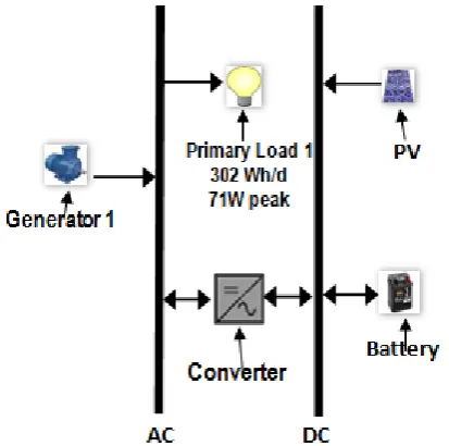
In order to fulfill the target of economical and optimal operation of systems, the optimal capacity configuration of components is very important in system design [4]. A typical micro grid system which includes PV, WT, energy storage systems, diesel generator, loads, and other distributed generations will be considered as shown in figure 1.
Fig. 1.Typical structure of micro grid system
generation installed capacity, diesel generator capacity, energy storage system capacity and resource data [16]. The micro grid system model in HOMER is shown in figure 2.
Fig. 2.The micro grid system model in HOMER
For reliability constraint, the economic performance of a renewable energy system can be significantly improved if a small portion of the annual load is allowed to go unserved. For example, a solar array and battery bank that do not have to meet an occasional large load may be significantly smaller than those that must meet the load at all times. This is especially true for those extreme cases with a peak load that occurs after several cloudy days. If it is acceptable for the system to be down for a small fraction of the year, or if unnecessary loads can be shed when the battery bank is low, significant capital cost may be saved. HOMER models this scenario with the maximum annual capacity shortage constraint. Set to 0% by default (in which the system must meet the entire load all of the time) a sensitivity analysis on this variable shows that the optimal system type might change if a small amount of the annual load (1/2% to 5%) is allowed to go unserved.
B. Micro grid control
Compared with traditional large-capacity thermal power, there are volatility in primary energy (such as wind and solar) and bidirectional flow in dynamic allocation of secondary energy (such as bidirectional energy flow between micro grid and large power grid, bidirectional energy flow in the bus of energy storage units) in micro grid. In addition, the load following reaction speed of each DG unit is very different. All these features add the complexity of micro grid automatic management, especially the optimal scheduling [6]. The micro grid system often has a hierarchical control structure The proposed hierarchical control system architecture comprises the following three control levels as shown in figure 3:
1) Local micro source controllers (MC) and load controllers (LC);
2) Micro grid system central controller (MGCC); 3) Distribution management system (DMS).
The MC takes advantage of the power electronic interface of the DG sources. It uses local information to control the
[image:3.595.54.261.88.293.2]voltage and the frequency of the micro grid in transient conditions.
Fig. 3. Hierarchical control structure of micro grid
MCs follow the demands from the central controller, when connected to the power grid, and perform local optimization of the DG active and reactive power production, and fast load tracking following an islanding situation. Local micro load controllers installed at the controllable loads provide load control capabilities following orders from the MGCC for load management.
The MGCC is responsible for the maximization of the micro grid’s value and the optimization of its operation. It uses the market prices of electricity and gas and probably grid security concerns to determine the amount of power that the micro grid should draw from the distribution system, thus optimizing the local production capabilities. The defined optimized operating scenario is achieved by sending control signals to the MCs and LCs. In this paper, noncritical, controllable loads can be shed when necessary, subject to the demand-side bidding (DSB). This operation can be considered equivalent to the secondary control of the larger power system. In market terms, the MGCC might represent the functions of an aggregator or energy service provider, who acts in the interest of one or more micro grids.
Conventional approaches to DMSs need to be enhanced with new features related to the operation of micro grids connected on the feeders. The information exchange within a typical micro grid is as follows: every m min, for example, 15 min, each DG source bids for the production for the next hour in m-min intervals. These bids are prepared according to the energy prices in the open market, the operating costs of the DG units plus the profit of the DG owner, and other needs for the installation facility, like, space heating. For example, if a DG owner has installed a CHP unit, it may wish to provide heat demand locally at a certain period. For this period, the bids sent to the MGCC should aim at maximizing this profit by participating in the electricity market.
optimizes the operation based on DG sources and load bids, and sends dispatch signals to both the MCs and LCs. Figure 4 shows the information exchange flow in a typical micro grid operating under such conditions.
Fig. 4. Information exchange flow between MCs and the MGCC
The optimization procedure depends on the market policy adopted in the micro grid operation.
A. Market Policies
In the first policy, the MGCC aims to serve the total demand of the micro grid, using its local production, as much as possible, without exporting power to the upstream distribution grid. For the overall distribution grid operation, such a behavior is beneficial, because at the time of peak demand, when energy prices in the open market are high, the micro grid relieves possible network congestion by partly or fully supplying its energy needs. From the consumers’ point of view, the MGCC minimizes the operational cost of the micro grid, taking into account open market prices, demand, and DG bids. The consumers of the micro grid share the benefits of reduced operational costs. In the second policy, the micro grid participates in the open market, buying and selling active and reactive power to the grid, probably via an aggregator or similar energy service provider. According to this policy, the MGCC tries to maximize the value of the micro grid, like, maximize the corresponding revenues of the aggregator, by exchanging power with the grid. The consumers are charged for their active and reactive power consumption at the open market prices. The micro grid behaves as a single generator capable of relieving possible network congestions not only in the micro grid itself, but also by transferring energy to nearby feeders of the distribution network.
B. Demand-Side Bidding
It is assumed that each consumer has low and high priority loads allowing him to send separate bids to the MGCC for each of their types. In our application, it is assumed that each consumer places bids in two levels reflecting his priorities. “Low” priority loads can be satisfied in periods of lower prices (shift) or not be served at all (curtailment). A similar approach can be used for more than two bid levels reflecting more precisely the consumer’s priorities [6]. Besides the control structure, is control methods research of
micro grid. The volatility of distributed generation and the differences of distributed generation units have increased the complexity and difficulty of micro grid control.
Distributed generations in micro grid are connected with the bus bar through power electronic devices that are very different from the generators that are connected directly with the grid. In addition, energy storage systems are usually equipped to increase the system inertia. So the traditional control methods are no longer applied properly in micro grid operation control. There are two control methods, master-slave control and peer-to-peer control. There is a main control unit in master-slave control to maintain the constant voltage and frequency (V/F). The main control unit adopts V/F control while other distributed generations adopt PQ control to output certain active and reactive power. Each unit is equal in peer-to-peer control, which is based on the method of external characteristics of declining. It associates frequency versus active power, voltage versus reactive power respectively. Through a certain control algorithm, the voltage and frequency will be adjusted automatically without the help of communication.
IV. CASESTUDY
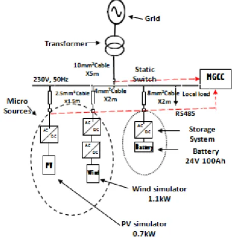
The structure of the micro grid (MG) system is shown in figure 5.
Fig. 5. Schematic diagram of a laboratory scale micro grid
[image:4.595.315.544.370.605.2]communication lines [4]. For the laboratory scale MG, based on the control strategies of the micro sources and the battery energy storage, a series of experiments were carried out, the power output of the distributed generators and battery, voltage and frequency of the AC bus were real-time measured and analyzed by the Power Quality Analyzer.
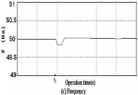
A. Transfer from islanded mode to grid-connected mode:
While switching from islanded mode to grid-connected mode, the voltage and frequency should be maintained within acceptable limits. The dynamic response process is shown in figure 6. At t2, the MG is synchronized to the grid
[image:5.595.318.553.53.215.2]and its voltage and frequency become equal to the values of the network. The PV simulator and wind simulator maintain constant power output and the battery will be charged by the grid. As shown in figure 6, the voltage and frequency will fluctuate accordingly with the grid.
Fig. 6. Transition from islanded to grid-connected mode
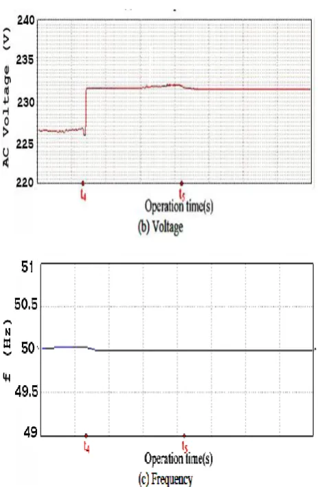
B. Transfer from grid-connected mode to islanded mode:
Also the voltage and frequency should be maintained within acceptable limits when switching from grid-connected mode to Islanded mode. The dynamic response process is shown in Figure 7. At t4, the MG is disconnected from the
grid and returns to Islanded mode operation. During this transition, the voltage and frequency will decrease slightly. For the safe operation, the distributed generators will disconnect from the MG (the output power become zero), the battery will increase its power output accordingly for the power balance of the system. Due to the voltage/frequency control of the battery inverter, the voltage and frequency of the MG are restored to the nominal value. Then at t5, the
Fig. 7. Transition from grid-connected to islanded mode
V. CONCLUSION
In this paper, discussion and analysis of micro grid design and control are carried out and the design method of HOMER is introduced briefly. The control methods of micro grid system are mainly demonstrated. The master-slave control and peer-to-peer control are mentioned. A laboratory scale MG system has been set up. The operation experimental results show that the laboratory-scale MG system can operate in grid-connected mode or islanded mode and hence increase the reliability of energy supplies, with a seamless transfer from the one mode to the other.
REFERENCES
[1] A. Ipakchi and F. Albuyeh, “Grid of the future,” IEEE Power
Energy Mag., vol. 7, no. 2, pp. 52–62, Mar. 2009.
[2] Shanthi .G, Dr.Elango K; “Optimal Power Scheduling of a Micro grid Using Distributed Generators”.
[3] Meena Agrawal & Arvind Mittal,”Micro Grid Technological Activities across the globe: A review”, IJRRAS Vol. 7 Issue 2 May 2011
[4] Yanbo CHE & Jian CHEN, “Research on Design and Control of Microgrid System”, Przeglad Elektrotechniczny (Electrical Review), ISSN 0033-2097, R. 88 NR 5b/2012
[5] Jian W., Xing-yuan L. & Xiao-yan Q., “Power System Research on Distributed Generation Penetration, Automation of Electric Power Systems”, vol. 29(24), pp. 90-97, 2005.
[6] Antonis G. Tsikalakis & Nikos D. Hatziargyriou,“Centralized Control
for Optimizing Micro grids Operation”, IEEE Transaction on Energy Conversion, VOL. 23, NO. 1, MARCH 2008
[7] A.M. Azmy and I. Erlich, "Impact of distributed generation on the stability of electrical power system," Power Engineering Society General Meeting, vol. 2, pp.1056-1063, 2005
[8] J.G. Slootweg and W.L. Kling, "Impacts of distributed generation on power system transient stability," Power Engineering Society Summer Meeting, vol.2, pp.862-867, 2002.
[9] R. Lasseter, A. Akhil, C. Marnay and J. Stephens et al, "White Paper on Integration of Distributed Energy Resources. The CERTS Microgrid Concept," Consortium for Electric Reliability Technology Solutions (CERTS), CA, Tech. Rep. LBNL-50 829, 2002.
[10] R.H. Lasseter and P. Piagi, "Control and Design of Microgrid Components, Final project report," PSERC publication 06-03, [Online]. Available: http://certs.aeptechlab.com/
[11] US Department of Energy Electricity Distribution Programme, Advanced Distribution Technologies and Operating Concepts - Microgrids, [Online]. Available: http:// www.electricdistribution. ctc .com/Micro grids .htm
[12] R. H. Lasseter, “Control and design of microgrid components”, PSERC Final Project Reports.
http://www.psercorg/cgipserc/getbig/publicatio/reports/
[13] J. Chen, Y. B. Che, and J. J. Zhang, “Optimal configuration and analysis of isolated renewable power systems.” Power Electronics Systems and Applications (PESA), 2011 4th International Conference on pp. 1284-1292.
[14] Eftichios Koutroulis, Dionissia Kolokotsa,Antonis Potirakis, Kostas Kalaitzakis. Methodology for optimal sizing of standalone PV–Wind. Solar Energy,2006(80): 1072-1088.
[15] S.M. Shaahid, M.A. Elhadidy. Economic analysis of hybrid PV diesel- battery power systems for residential loads in hot regions. Renewable and Sustainable Energy Reviews,2008(12): 488-503. [16] T. Givler and P. Lilienthal, “Using HOMER® Software, NREL’s