Evolving technologies for growing, imaging and
analyzing 3D root system architecture of crop
plants
Miguel A. Pi
~
neros
1, Brandon G. Larson
1, Jon E. Shaff
1, David J. Schneider
1, Alexandre Xavier Falc
~
ao
2, Lixing Yuan
3,
Randy T. Clark
1, Eric J. Craft
1, Tyler W. Davis
1, Pierre-Luc Pradier
1, Nathanael M. Shaw
1, Ithipong Assaranurak
4,
Susan R. McCouch
4, Craig Sturrock
5, Malcolm Bennett
5,6and Leon V. Kochian
1*
1USDA-ARS, Robert Holley Center for Agriculture and Health, 538 Tower Road, Ithaca, NY 14580, USA,2Department of Information Systems,
Institute of Computing, University of Campinas, Av. Albert Einstein, 1251, CEP 13083-852, Campinas, SP, Brazil,3Department of Plant Nutrition, China Agricultural University, Beijing 100193, China,4Department of Plant Breeding and Genetics, Cornell University, Ithaca, NY 14853, USA, 5Centre for Plant Integrative Biology, School of Biosciences, University of Nottingham, Sutton Bonington, LE12 5RD, UK,6College of Science, King
Saud University, Riyadh 11451, Kingdom of Saudi Arabia. *Correspondence:[email protected]
Abstract A plant’s ability to maintain or improve its yield under limiting conditions, such as nutrient deficiency or drought, can be strongly influenced by root system architec-ture (RSA), the three-dimensional distribution of the different root types in the soil. The ability to image, track and quantify these root system attributes in a dynamic fashion is a useful tool in assessing desirable genetic and physiological root traits. Recent advances in imaging technology and phenotyp-ing software have resulted in substantive progress in describing and quantifying RSA. We have designed a hydroponic growth system which retains the three-dimen-sional RSA of the plant root system, while allowing for aeration, solution replenishment and the imposition of nutrient treatments, as well as high-quality imaging of the root system. The simplicity andflexibility of the system allows for modifications tailored to the RSA of different crop species and improved throughput. This paper details the recent
improvements and innovations in our root growth and imaging system which allows for greater image sensitivity (detection of fine roots and other root details), higher efficiency, and a broad array of growing conditions for plants that more closely mimic those found underfield conditions.
Keywords:Abiotic stress; digital root phenotyping; mineral nutrition; root system architecture
Citation:Pineros MA, Larson BG, Shaff JE, Schneider DJ, Falc~ ~ao AX, Yuan L, Clark RT, Craft EJ, Davis TW, Pradier PL, Shaw NM, Assaranurak I, McCouch SR, Sturrock C, Bennett M, Kochian LV (2016) Evolving technologies for growing, imaging and analyzing 3D root system architecture of crop plants.J Integr Plant Biol58: 230–241 doi: 10.1111/ jipb.12456
Edited by:William J. Lucas, University of California, Davis, USA ReceivedOct. 19, 2015;AcceptedDec. 16, 2015
Available online on Dec. 18, 2015 atwww.wileyonlinelibrary.com/ journal/jipb
© 2015 Institute of Botany, Chinese Academy of Sciences
INTRODUCTION
In addition to their obvious role in providing mechanical stability to aboveground structures, roots play many essential functions in the biology of terrestrial plants, including the uptake, storage and transport of water and nutrients. Differences in spatial distribution of the root system throughout the soil’s profile can have substantial impact on the efficiency for carrying out physiological functions, such as water and nutrient acquisition, carbon distribution, and the ability of the plant to adjust to abiotic stresses, such as low phosphorus, salinity and high soluble aluminum (Al3þ) (Lynch
2007; Munns and Tester 2008; Tester and Langridge 2010;
Lynch2011;Zhu et al.2011). From an agricultural perspective,
the root systems of crop plants have traditionally not been the subject of extensive selection for desirable breeding pheno-types. For the most part, because of the opaque nature of soils and similar root growth media, this type of selection has been performed“blindfold”due to the absence of practical methods to measure the three-dimensional (3D) distribution of root systems in their natural environment.
The recent developments allowing the detailed phenotyp-ing of plant root architecture has resulted in a pivotal new platform that now allows for the genetic mapping, analysis and identification of genes underlying root architecture traits for directed molecular breeding approaches improving crop nutrient efficiency (seeLi et al.2016review in this special JIPB issue). Identifying, evaluating and selectively introducing both intrinsic and environmentally responsive root architectural characteristics into crop molecular breeding programs may be a promising area for improving crop production on resource-limited agricultural systems (de Dorlodot et al. 2007). Generating robust, reliable and relevant root and rhizosphere trait information is the key to understanding root: soil interactions and to ensure enhanced and sustainable crop
AWindows is a registered trademark of Microsoft Corporation in the
United States and/or other countries.
BMac and OS X are trademarks of Apple Inc., registered in the U.S. and
other countries.
CLinux1is the registered trademark of Linus Torvalds in the U.S. and
other countries.
Free
Access
New
production in a changing climate (Clark et al. 2011;Downie et al.2015). Ideally, one would want to conduct these analyses of root system architecture (RSA) in field-grown plants, thereby extracting the most accurate representation of root growth in an agriculturally relevant context. However, soil confounds root system imaging, as root systems in soils tend to be complex and elaborate, preventing their easy recovery for observation. In addition, given the low throughput, this approach is not feasible for genetic studies requiring phenotyping of a meaningful number of genetically diverse lines of interest. Therefore, approaches using biologically simpler systems have been adopted to overcome these limitations while still generating meaningful data. One natural path is to exploit and adapt existing imaging technologies to the peculiar problem of characterizing root systems. Imaging and image processing have revolutionized plant phenotyping, becoming major tools for phenotypic trait measurement, with the ultimate goal of providing quantitative analyses of plant structure and function relevant for those traits that underlie plant adaption to low-input agriculture and resource-limited environments (Kumar et al.2015). However, this choice leads to a second fundamental challenge–the existence of multiple length scales. Since the ratio of the length of a primary root to the diameter of a root hair can be as large as 104, simple dimensional considerations suggest that a brute force approach would require on the order of (104)3¼1012voxels to fully characterize the spatial distribution of a typical root system. These considerations suggest inevitable tradeoffs among the requirements of growth and imaging under realistic conditions, the ability to image root structures on all relevant length scales, and the time and expense of image acquisition and analysis. To that end, the design of a high-throughput and low-cost screening systems to measure RSA, both spatially and temporally, should become an important and effective tool to help quantitatively evaluate RSA features that underlie important agronomic traits (Fiorani and Schurr 2013;Topp et al.2013;Downie et al.2015).
In the present manuscript we report on our recent improvements and developments on our original root 3D-imaging platform, RootReader 3D (Clark et al. 2011), for phenotyping of 3D root traits during early seedling develop-ment. Briefly, this method involves the reconstruction of a 3D model of a root system from a series of 2D digital images of the root system taken from different angles. The silhouette of the root system in each view is used to identify pixels where the background is visible. Since the background is visible precisely when there is no root tissue blocking the path from that pixel through the imaging volume to the background, all voxels in the imaging path that lie along the path may be marked as empty. This process is repeated for each pixel and each image, resulting in a set of voxels where there is positive evidence for the absence of root tissue. The voxels that have not been marked empty constitute the 3D reconstruction. Figuratively speaking, a 3D reconstruction obtained by silhouette-based imaging methods should be viewed as what is left after one carves away those portions of the imaging volume where it has been possible to exclude the presence of root tissue. It is important to note that thefidelity of the reconstruction is strongly dependent on the contrast between the root system and other objects in the image, as well as the methods used to define the silhouette.
Here we describe an improved root imaging system that is low cost, easy to assemble, using mostly commercially available parts and software of our own design, which is freely available to all. We have also designed growing systems that are simpler and less expensive to build and use than our gellan gum system, and can be adaptable for use with typical crop plant species. At the same time we have strived to bring the growing systems and media closer to what plants might experience in the field, increasing the relevance of the phenotypic data.
RESULTS AND DISCUSSION
In the original 3D-root phenotype system described earlier (Clark et al.2011), plant roots were grown in a glass cylinder containing transparent gellan gum, under sterile conditions. To image the plant roots in this system, the gel-filled cylinder was submerged in a rectangular glass-walled water-filled tank to minimize refraction, and then imaged over as the root system (and plant) were rotated through 360°, with 2D images taken every 9° (40 images per 360° of rotation). Image processing using the RootReader 3D software created 3D root models, which allowed for: a) classification of roots intofive different root types, as well as: b) quantification of 27 different root traits which described the root’s spatial characteristics in both static and dynamic fashions. Although this approach has proven to be extremely valuable in generating data, the extensive use of a gel-based system has unveiled some inherent disadvantages. From a technical point of view, although constituting a significant improve-ment of throughput over other 3D root phenotyping techniques, the time and costs associated with the sample preparation (i.e., preparation of the gel/nutrient system, autoclaving, sterile filtering, pouring gels, planting under sterile conditions) and the loss of replicates due to fungal and bacterial contamination still represents a throughput con-straint for an average laboratory.
In addition to these practical downsides, and in regard to the biology, we have regularly observed that although being well suited for studying rice roots, for yet undetermined reasons other plant species (e.g., maize and sorghum) do not grow well in the gellan gum media. Their root systems are much smaller and stunted compared to maize and sorghum root systems grown in hydroponics. Our earlier studies had indicated that the use of a gellan gum also had a smaller affect on rice root system growth and architecture. Growth of the entire root system and growth of certain root types was less in gellan gum compared to that in hydroponics and sand media (see table II in Clark et al. 2011). These observations highlighted the need, especially for plant species other than rice, to move away from root growth in gellan gum cylinders and transition to other more experimentally flexible root growth environments. The following narrative focuses on the evolution of the 3D imaging platform, describing the various innovations that have been made in the way that we grow and image plants for evaluating root system architecture traits.
Mesh support system for growth and imaging
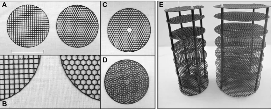
environment provided by the gellan gum media previously used. The goal was to develop an inexpensive root growth system to provide support that was compatible with a variety of liquid and solid media, did not complicate image acquisition and processing, or unduly compromise the quality of final reconstructions. The new root growth design is based on the use of a system of plastic mesh discs supported by spacers and threaded rods (Figure 1). The Acrylonitrile butadiene styrene (ABS) plastic mesh discs are constructed from plastic ABS stock using a 3D printer, and are arranged in a series of layers with increasing intervals between successive layers, such that the plant roots can grow through the mesh in the discs and the sequential layers of mesh discs help retain root distribution and shape. The 3D printing technology makes it straightforward to customize the shape of the mesh openings (square or hexagonal) and the size of the discs (diameter and thickness), according to experimental requirements. The upper disk of the stack includes an additional opening for the planting of larger seedlings (Figure 1C). Stacking of the disks in 90° rotation intervals generates a semi-random and tortuous mesh configuration to anchor the overall root architecture (Figure 1D, E).
Data acquisition and processing
The digital imaging system has also evolved from that previously described in Clark et al. (2011). In an effort to increase contrast and therefore root image resolution, high-intensity broad-spectrum LED lighting and a black background were implemented, in contrast to the back lighting previously used for the gellan gum system. Likewise, in an effort to increase flexibility and lower overall costs, a new control system has been developed using the Raspberry Pi single-board computer (Raspberry Pi 2 Model B; https://www. raspberrypi.org/), which is a fully featured Linux PC providing
four USB port instrument control, an Ethernet port for data transfer, and a set of general purpose input/output (GPIO) pins allowing for various hardware components to be integrated directly with the computer. The ultimate goal is to produce the Raspberry Pi as a stand-alone component, with all of the necessary software pre-installed, which can be connected to a motor and digital camera for simple image collection and 2D analysis.
Building on top of the original 3D imaging framework, introduced in Clark et al. (2011), the credit-card sized Raspberry Pi serves as the computer for controlling the camera and turntable. The GPIO pins are connected to a motor controller for adjusting the speed and rotation of the turntable and an open-source digital camera library is used to interface with a USB-connected digital camera. New features are currently being added to the new flexible Raspberry Pi platform. Automating the camera calibration process eliminates subjective calibration parameters, reduc-ing the overall processreduc-ing time, and facilitatreduc-ing the repeat-ability of experiments. For data preservation and versatility, raw images, experiment details and image processing settings are being stored in hierarchical data format (HDF)
files. The latest update is a new graphical user interface (GUI) that will be used for the various stages of the phenotyping process (i.e., image capturing, 2D processing and 3D reconstruction). This will make the entire process more intuitive and efficient.
The number of images acquired in a single revolution can seriously reduce the resolution that is actually achieved in the
[image:3.595.74.529.459.642.2]final reconstruction. This consideration is particularly impor-tant for fine roots and root hairs. A reasonable balance between resolution and throughput can be achieved by acquiring 100 images per revolution. The presence of the mesh system modestly increases the complexity of computing the
Figure 1. Components of the ABS plastic mesh vertical towers that allow unrestricted root growth but maintain the 3D root architecture
silhouette of the root system. The computational challenge is reduced by modifications we have made to the data acquisition system, including the use of side illumination, a black background and the non-reflective black components for the mesh system. Under these conditions, the background is dark, roots appear gray or white, and spurious reflections are minimized. Currently, the silhouette is obtained by converting the cropped, down-sampled input images to grayscale followed by adaptive thresholding using Otsu’s algorithm (Otsu1979) to create two distinct classes of pixels assigned foreground (roots) and background. Visual inspec-tion reveals that this initial thresholding step does not capture all of the pixels where roots are visible. As might be expected from the dendritic nature of roots, the low-intensity pixels initially misclassified as background are often in close proximity to higher-intensity foreground pixels. These low-intensity pixels can be recaptured by dilation – adding all background pixels that lie within a radius offive pixels of some foreground pixel. This dilated foreground set is iteratively
filtered to remove pixels of very low intensity. Each iteration involves computing the mean pixel intensity for a circular neighborhood around each pixel in the foreground set. If the pixel intensity is greater than a user-specified factor of this local mean intensity, then the pixel is retained in the foreground set. Good results are obtained using two iterations with circular neighborhood of radius 2.5 pixels and an intensity scaling factor of 0.9. Finally, the set of foreground and background pixels are assigned the colors black and white, respectively. The processed images defining the visible root silhouettes are used as input to RootReader 3D.
The thresholding andfiltration steps described above are designed to classify pixels corresponding to mesh system components as background. So, each silhouette contains horizontal bands corresponding to the mesh disks and vertical bands corresponding to the mesh supports. Since each image is a different view of the same root system, there is a natural redundancy of the information in the image set. The robust reconstruction algorithms used in RootReader 3D exploit this natural redundancy to effectively eliminate the impact of the vertical mesh supports. Unfortunately, the horizontal bands are in the same position in all silhouettes so the reconstruc-tions obtained from RootReader 3D contain horizontal slices indicating the consistent obstruction by the plastic mesh disks.
Skeletonization, the reconstruction of 3D models from 2D images, as well as the quantification of root traits, was performed using the previously described RootReader 3D software (Clark et al.2011). The RootReader 3D analysis tool has been converted into a stand-alone application that can be run on Linux, Windows and Mac systems. The systematic absence of data in certain vertical bands also affects the evaluation of traits from thefinal reconstruction. Currently, the formulae defining each trait are applied without change to the voxels in the reconstruction. Therefore, the numerical values obtained in hydroponics are biased in comparison to the quantities obtained in gellan gum or other completely transparent media. This implies that the numerical values of traits are not comparable. Fortunately, the spatial bias in the trait evaluation can be ignored for all plants grown and imaged with the same mesh.
During reconstruction, the current implementation of RootReader 3D employs a 3D array of voxels to model the imaging volume. As a result, the total number of voxels is limited by the amount of memory available for this array. In practice, this limit is about 109elements. This restriction limits
the theoretical maximum resolution of the reconstruction. The input images are cropped and down-sampled as necessary to work within these memory constraints. This constraint can be relaxed considerably by using adaptive data structures such as sparse octrees (Laine and Karras2011) to represent the imaging volume.
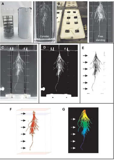
Figure 2illustrates the general workflow for root system imaging using mesh support systems. Details regarding conditions for hydroponic growth are provided in the following section. Plants may be grown in mesh systems placed in glass cylinders and imaged without removing the plant (Figure 2A), or grown in free-standing mesh systems in hydroponic growth tanks and moved to the imaging tank (Figure 2B). The latter approach is useful for studies involving large numbers of plants. The color images obtained from the camera (see Movie 1A for example) are converted to grayscale (Figure 2C), subjected to thresholding and iterativefiltering (Figure 2D; Movie 1B), andfinally inverted (Figure 2E; Movie 1C) as described above. Note the narrow horizontal bands caused by removing the images of the plastic mesh discs from the images of the root system (cf.Figures 2C, E). The inverted images are processed by RootReader 3D to obtain a 3D reconstruction (Figure 2F) and associated root traits. The voxels in the reconstruction can be visualized as a point cloud (Figure 2G) or animated as a movie (Movie 1D) using software tools available athttp://foo.ars.usda.gov.
Root system growth and imaging in hydroponics
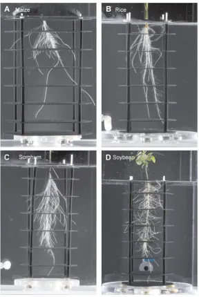
A hydroponic-based system significantly improves experimen-talflexibility in that plants can be grown with a constant supply of a well-defined nutrient composition and the solution can be easily replaced or replenished. In addition, a different nutrient composition (i.e., treatments) can be easily imposed at any given time since the medium is not fixed. Gentle aeration ensures that the solution is well mixed (no diffusion limitations to consider) and it is oxygenated adequately. We have easily grown a number of different plant species (e.g., rice, sorghum, maize, cucumber and soybean) using this hydroponic-based mesh system (Figure 3; Movies 2A through D).
Evaluation of the Turface-based platform using X-ray computed tomography
Figure 2. Depiction of plant roots grown hydroponically in the ABS plastic mesh vertical towers and then examples of 2D image modification and 3D reconstructions of the root systems
mesh system contained in a plastic container filled with Turface (Figure 4A, B). For the rice (cv. Azucena) plant depicted in Figure 4, the plastic cylinders housing the rice seedling, mesh and Turface were bottom irrigated by placing the cylinders in a tubfilled with nutrient solution (Figure 4C). After plant growth for 9 or 13 d, the plant growth cylinders were submerged into a tub of water, gently removing and washing away the Turface, and freeing up the mesh tower and the root system with minimal disruption. The mesh tower was then imaged using the same protocol described above for the hydroponically grown plants. The root system of a Turface-grown rice plant is depicted inFigure 4D; Movies 3A (Day 9) and 3B (Day 13).
Using X-ray computed tomography (CT), we examined basic RSA properties for both rice genotypes grown in
Turface, in the presence or absence of the stack-mesh system. The reader is referred to Sturrock et al. (2015)
[image:6.595.154.443.60.491.2]for a detailed description of the methodology and the Materials and Methods here. Root systems in Turface and soil columns were scanned using a Phoenix v|tome|x m industrial X-ray CT scanner (GE Sensing and Inspection Technologies GmbH, Wunstorf, Germany) at the Hounsfield Facility, University of Nottingham. Data were reconstructed for visualisation using datos|x software (GE Sensing and Inspection Technologies GmbH, Wunstorf, Germany) and data was visualized using VGStudio MAX 2.2 (Volume Graphics GmbH, Heidelberg, Germany). Images of the rice root systems were separated from the images of the Turface material by segmentation and quantified using a combina-tion of region growing segmentacombina-tion techniques in
Figure 3. Examples of 2D images of root systems from different plant species grown in hydroponics using the plastic mesh system
VGStudioMAX and RooTrak software (Mairhofer et al. 2012). In the present study, the depth of root architecture detail is limited due to the large pot size used in the CT scan, which reduced the detection of some of the fine lateral roots.
The undisturbed morphology of rice root systems for two rice genotypes, a paddy rice grown inflooded conditions, IR64, and an upland rice, Azucena, grown agriculturally under
[image:7.595.117.480.63.332.2]non-flooded conditions, are shown after growth in Turface and soil in Figure 5A, B and C, respectively. This non-perturbative
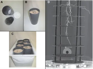
Figure 4. Components and implementation of the granular soil-like media, Turface, for root system architecture studies
(A)The plastic mesh tower (bottom left in panelA) is placed into a plastic cylinder with a lid at the bottom. (B)Cylinder/mesh systemfilled with pretreated Turface. (C)Filled cylinders placed into growth tubsflooded with nutrient solution. (D)At the desired time point (Day 9 in this example for Azucena rice), the Turface is gently washed off, and the root system contained in the plastic mesh systems is then imaged using the same protocol described earlier for the hydroponically grown root system.
[image:7.595.117.480.502.698.2]approach revealed similar and comparable meandrous root morphologies for rice seedlings grown in Turface compared to those imaged after the Turface was gently washed off (cf.
Figures 4D, 5B). Most noticeably, this distinct root morphology approximates that observed in roots grown in soil (Figure 5C). Three-dimensional reconstructions from the CT scans were generated to perform a comparative analysis of 3D root traits for both genotypes grown in Turface with the absence or inclusion of the plastic mesh system (See Movies 4A through 4D). Similar to what has been described with other platforms, CT scan reconstructions validated that the Azucena root system was significantly deeper than IR64’s when they were grown in Turface media (Table S1). Most importantly, no qualitative difference in the basic root dimensions were recorded between reconstructions performed in seedlings growing in Turface with or without the inclusion of the plastic mesh system (Table S1). Overall, these observations suggest that the root morphology recorded in the Turface platform are a result of this medium approximating realistic soil impedance characteristics, rather than an effect of the plastic mesh system
in biasing RSA, thus providing an initial validation of the potential usefulness of Turface, and other similar granular soil-like media, under these conditions.
Comparison of root architecture traits from plants grown in hydroponics, gellan gum and Turface
[image:8.595.76.518.308.677.2]The implementation of the plastic mesh system for hydro-ponic or Turface-based growth of plant roots has significantly simplified sample preparation (i.e., germination and plant growth) by removing the need for laborious sterile media preparation and plant growth in independent containers as required in the gellan gum system. The gellan gum was used previously to conduct a comparative study among root traits from the same two rice (Oryza sativa) genotypes, Azucena and IR64 (Clark et al.2011) that we employed in this study. In the present study we also compared root system traits for Azucena and IR64 to evaluate the hydroponic and Turface platforms in terms of their ability to capture the root trait differences between these genotypes, relative to those reported earlier (Clark et al.2011).Figure 6illustrates typical
Figure 6. 2D images for the rice genotypes IR64 (left column) and Azucena (center column) grown in hydroponics (top row) after 8 d or Turface (bottom row) after 9 d
images obtained from 8- to 9-d-old seedlings of each rice genotype grown in the different platforms in Magnavaca solution (Magnavaca et al.1987). Before proceeding with a quantitative analysis of the root traits, it is worth noticing that overall, the root morphology and root distribution (i.e., architecture) of seedlings growth under hydroponics resem-bled that observed in gellan gum. In contrast, roots grown in Turface were morphologically more distinct, with the root system being less elaborated, less branched and with more tortuous root morphologies, presumably due to thigmotropic responses as the growing root encounters and grows around impenetrable clay particles.
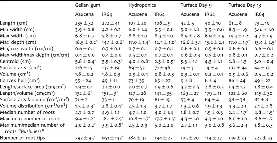
A total of 18 root architecture traits were quantified from the 3D reconstructions for rice plants grown in gellan gum or hydroponics for 9 d, or in Turface for 9 and 13 d (see Movies 5A through 5D for examples of 3D reconstructions for each growth media). Table 1 summarizes the various root architecture traits calculated for the three growth conditions. When grown in gellan gum, 8 out the 18 static traits were significantly different between Azucena and IR64, consistent with our earlier findings (Clark et al. 2011). In general, the Azucena root system was significantly deeper, with a deeper center of mass (i.e., centroid) relative to that recorded for IR64. The Azucena genotype also showed a smaller maximum number of roots (defined as the number of roots at the 84th percentile of a sorted list (smallest to largest) of root counts from all horizontal cross-sections through the entire root system), which translated into a reduced“bushiness”(i.e., the ratio between median and maximum number of roots). Although no significant differences in total length, surface area, volume and convex hull parameters were observed
between the two genotypes, length to surface area or volume ratios, as well as the volume distribution (defined as the ratio of the volume of the root system contained above one-third depth of the root system and the volume of the root system contained below one-third depth of the root system) were significantly smaller in Azucena than IR64.
[image:9.595.57.539.448.697.2]When grown in hydroponics, a comparative analysis of these 18 traits between these two genotypes, yielded comparable results, as four of the traits remained signifi -cantly different between the genotypes (e.g., maximum depth, centroid, maximum number of roots and bushiness). Likewise, the length to volume ratio and volume distribution in hydroponics showed similar trends to gellan gum-grown roots, being smaller in the Azucena genotype, although not being significantly different at the confidence interval tested (i.e.,P<0.01) withP-values of 0.017 and 0.014, respectively. The similarity in the outcomes on both gellan gum and hydroponic platforms endorses the usefulness of the outlined technical advances. For the root traits for plants grown for 9 d in Turface, the same general trends as seen in gellan gum and hydroponic-grown roots were observed, in that Azucena had a deeper root system than IR64. However, the differences were not statistically significant, possibly due to the root systems growing more slowly in Turface than in hydroponics and gellan gum. In fact, as the plants were grown for a longer period of time (i.e., Day 13) the differences between the more elaborated root systems (Table 1and Movies 5E, F) of the two rice genotypes became more pronounced (e.g., differences in maximum depth became statistically significant). Attempts to characterize root traits past this time point proved unsuccessful as the
Table 1. Root system architecture traits quantified for the Azucena and IR64 rice genotypes grown in gellan gum (n¼7) for 8 d, hydroponics (n¼6) for 8 d or Turface for 9 (n¼6) or 13 (n¼5) d
Gellan gum Hydroponics Turface Day 9 Turface Day 13
Azucena IR64 Azucena IR64 Azucena IR64 Azucena IR64 Length (cm) 23532 27241 10720 1089 425 4010 618 7310 Min width (cm) 3.90.8 4.20.2 6.01.4 5.50.6 5.01.8 3.50.6 8.31.9 5.6.1.0 Max width (cm) 6.80.7 5.80.7 8.81.0 8.31.0 8.92.8 6.90.9 14.31.2 9.71.9 Max depth (cm) 18.50.2 14.10.6 17.01.4 12.41.0 16.63.1 15.22.1 17.01.7 13.42.5 Min/max width (cm/cm) 0.60.1 0.70.1 0.70.1 0.70.1 0.60.1 0.50.1 0.60.1 0.60.1 Max width/max depth (cm/cm) 0.40.0 0.40.0 0.50.1 0.70.1 0.60.3 0.50.1 0.80.1 0.70.2 Centroid (cm) 5.80.4 3.50.3 4.00.8 2.30.5 5.31.1 4.31.1 2.81.3 3.00.4 Surface area (cm2) 12615 13219 6952 7146 143 144 10294 4417 Volume (cm3) 1.80.2 1.80.3 0.90.4 0.80.3 0.30.1 0.20.1 0.90.6 0.50.2 Convex hull (cm3) 5524 4911 7335 6527 98 64 8644 4922 Length/surface area (cm/cm2) 1.90.1 2.10.0 2.00.7 1.90.6 3.20.5 2.80.3 1.41.2 1.80.4
Length/volume (cm/cm3) 1326 1513 12728 14135 16927 17911 10260 14530 Surface area/aolume (cm2/cm3) 712 731 7019 8119 534 644 9838 828 Volume distribution (cm3/cm3) 1.50.3 2.80.4 2.51.3 3.71.7 1.30.6 1.91.3 4.32.1 2.10.8
Median number of roots 4.70.7 4.91.1 4.71.0 4.01.4 1.80.7 1.50.5 2.41.7 4.81.5 Maximum number of roots 9.41.2 18.12.5 10.81.7 17.71.5 4.31.0 4.31.0 6.01.0 8.61.7 Maximum/median number of
roots“Bushiness”
2.00.2 3.90.8 2.50.9 5.02.0 2.71.1 3.00.8 3.62.4 1.80.3
root system growth was constricted by the diameter and deepness of the mesh tower.
In this manuscript, we have presented several recent lines of development for a low-cost 3D root system imaging platform. The introduction of a mesh system upon which plants can be grown and maintain root system configuration during imaging represents an important advance over other optical imaging platforms that depend on growth and imaging in low-density gellan gum or related semi-solid/semi-transpar-ent media. Its strengths lie in the adaptability to differsemi-solid/semi-transpar-ent plant species and experimental requirements, and ease of sample preparation and handling. The cost of the entire system is quite reasonable and places this research method-ology accessible in many laboratories. The use of simple, low-cost digital cameras and computers (such as the Raspberry Pi 2) to acquire and control imaging and to process these acquired images, makes this system a sensible choice. Improvements in our software and hardware, both of which are currently in the pipeline, will undoubtedly decrease the costs and improve image resolution and sample throughput further, while at the same time increasing this technique’s power and value.
Here we have developed two new plant growth platforms for quantitation of 3D root architecture traits that are compatible with the mesh support, lighting and data acquisition systems. Hydroponic growth is known to be applicable to a very wide variety of plant species, and has lower overall cost in comparison to growth and imaging in gellan gum cylinders. In addition, it is possible to impose changes in the chemical composition of the nutrient solution during an experiment (e.g., impose salinity or a nutrient deficiency). The second growth system employs Turface, a commercial product consisting of non-swelling illite clay particles, to create a physically heterogenous environment for root growth. An initial small-scale X-ray CT study of the well known rice varieties, IR64 and Azucena, showed that the mesh systems did not have an obvious effect on the root system architecture, and the gross morphology of both cultivars appeared similar in Turface and soil, and somewhat different from the root traits observed in hydroponics.
The use of a mesh support system in conjunction with soil substitutes such as Turface should make it possible to image root systems of plants grown under water -limited (drought) conditions. Control of water status in solid media may be achieved by measuring its moisture content using sensors embedded within the media matrix and feedback from these sensors can be used to control watering events using drip irrigation. As such, one can conduct experiments on drought stress and its effect on RSA for critical traits, such as root angle and root depth (Uga et al.2015), or select for drought tolerance from a number of lines. Other media, such as glass beads (Courtois et al. 2013), large particle sand, Nafion, a synthetic polymer with ionic properties (Downie et al.2012), and plastic pellets may also be compatible with growth and imaging using a mesh support system (data not shown).
One problem we still need to address is the horizontal gaps in the root system 3D reconstructions caused by subtraction of the plastic mesh disc images. Several approaches are being considered, including the use of
computational methods to join the images of roots above and below the mesh disks, and the use of meshes constructed from very fine fluorocarbon filaments in conjunction with multiple cameras angled to afford views through the mesh layers.
Another challenge to anyone using image analysis to study RSA is the larger question of what root traits are important for the biological process under investigation. The 3D model obtained by the reconstruction process should be viewed like a molecular model of a protein obtained by X-ray diffraction. In both cases one must define ways to extract answers to specific questions from the generic model. As stated by Rousseau et al.,“All these systems generate digital images which contain information on plant structure, function and growth. Whilst there is a real sense in which an image is a measurement, the more interesting task lies in extracting quantitative measurements from images which have intrinsic value for biologists”(Rousseau et al.2015). Indeed, the suite of techniques currently used by researchers for imaging root systems and quantifying root traits are neither unique nor complete. Answers to new questions may well require new ways to extract quantitative traits from root 3D reconstructions.
MATERIALS AND METHODS
Plastic mesh system for root growth and imaging
Growth and imaging in hydroponic media
Seedlings arefirst germinated in paper, and then transferred into the 3D hydroponics mesh tower, where the seedling is then secured in position with a piece of foam, slotting the shoot into a notch cut into the foam and resting the foam on the top layer of the mesh tower. Each mesh tower containing the seedling can be placed either in a separate glass cylinder (i.e., mimicking the gellan gum system) with an aeration line or multiple mesh stands can be seated freely in a large aerated tub of growth solution (Figure 2A, B). Seedlings are grown under standard conditions (aeration, temperature, photope-riod) with the nutrient solutions shielded from light. We have readily grown a number of different plant species (e.g., rice, sorghum, maize and soybean) using this hydroponic-based mesh system (Figure 3; Movies 2A through D).
Growth and imaging in Turface
While growing plants in hydroponics is elegant and simple, the mesh support system can also be used to simulate root growth under field conditions by incorporating a physical heterogeneous solid substrate. From a practical point of view, combining the mesh system with the use of conventional soils or artificial soil mixes was not possible since both of them are not readily or completely washed from the roots, discoloring and obscuring roots, both of which detract from image analysis and 3D reconstruction of RSA. Alternatively, we have used Turface (Turface MVP, http://www.turface.com/) as a granular, unsaturated soil-like substrate that is readily available commercially, is low cost, and has physico-chemical properties similar to soils. Briefly, Turface MVP is a stabilized baked ceramic aggregate with a 1.0–2.0 mm particle size range, formed byfiring non-swelling illite clay at temperatures no less than 650 °C. It is non-cohesive, drains rapidly, retains sufficient plant-available water, allows higher oxygen ex-change to the root system, yet is easily washed off the roots (van Bavel et al.1978; Steinberg et al. 2005). The support provided by the mesh system allows the plant to be submerged in a tank and imaged using the same systems used for hydroponics. This system is also compatible with drip irrigation, with no loss of aeration when compared to commercial soil mixtures (Steinberg et al. 2005). We have established a washing and pre-treatment regime to equili-brate the exchange sites on the Turface particles and to allow a uniform supply of nutrients to the plant.
Turface was used as a soil-like growth medium using the same plastic mesh towers that are part of the hydroponic growth system (Figure 4). For this purpose, the mesh towers are placed into a plastic cylinder that can later be easily disassembled, by means of either a longitudinal seam or a lid at the bottom of the cylinder (Figure 4A). The cylinder is then
filled with pretreated Turface (Figure 4B), placed into growth tubs and flooded with growth solution (Figure 4C). Germi-nated seedlings are placed into the top layer of the mesh, gently covered with moist Turface, and grown in theflooded Turface /mesh replenishing the growth solution every 4 d. Having reached the desired growth stage, the cylinders are submerged into a tub of water, and gently removed, thereby washing away the Turface, and freeing up the mesh tower and the root system with minimal disruption. The mesh tower is then imaged using the same protocol described above for the hydroponics (Figure 4D; Movies 3A).
ACKNOWLEDGEMENTS
C.J.S. and M.J.B. acknowledge the support of the Biotechnol-ogy and Biological Sciences Research Council and Engineering and Physical Sciences Research Council funding to the Centre for Plant Integrative Biology. We also acknowledge funding in the form of a Biotechnology and Biological Sciences Research Council Professorial Research Fellowship (to M.J.B.); Euro-pean Research Council Advanced Investigator Grant funding (FUTUREROOTS) (to M.J.B); and the Distinguished Scientist Fellowship Program (DSFP) at King Saud University to M.J.B.
AUTHOR CONTRIBUTIONS
M.A.P., J.E.S., D.J.S., A.X.F., Y.L., R.T.C., T.W.D., S.R.M., C.R., M.B. and L.V.K. designed experiments, B.G.L., J.E.S., Y.L., R.T. C., E.J.C., P.L.P., N.M.S., I.A. and C.S. conducted experiments, M.A.P., J.E.S., D.J.S., A.X.F., Y.L., R.T.C., T.W.D., S.R.M., C.R., M.B. and L.V.K. interpreted data, and M.A.P., J.E.S., D.J.S., C.S., M.B. and L.V.K. wrote the manuscript.
CONFLICT OF INTEREST
The authors have no conflicts of interest to declare.
REFERENCES
Clark RT, MacCurdy RB, Jung JK, Shaff JE, McCouch SR, Aneshansley DJ, Kochian LV (2011) Three-dimensional root phenotyping with a novel imaging and software platform.Plant Physiol156: 455–465
Courtois B, Audebert A, Dardou A, Roques S, Ghneim-Herrera T, Droc G, Frouin J, Rouan L, Goze E, Kilian A, Ahmadi N, Dingkuhn M (2013) Genome-wide association mapping of root traits in a japonica rice panel.PLoS ONE8: e78037
de Dorlodot S, Forster B, Pages L, Price A, Tuberosa R, Draye X (2007) Root system architecture: Opportunities and constraints for genetic improvement of crops.Trends Plant Sci12: 474–481
Downie H, Holden N, Otten W, Spiers AJ, Valentine TA, Dupuy LX (2012) Transparent soil for imaging the rhizosphere.PLoS ONE7: e44276
Downie HF, Adu MO, Schmidt S, Otten W, Dupuy LX, White PJ, Valentine TA (2015) Challenges and opportunities for quantifying roots and rhizosphere interactions through imaging and image analysis.Plant Cell Environ38: 1213–1232
Fiorani F, Schurr U (2013) Future scenarios for plant phenotyping. Annu Rev Plant Biol64: 267–291
Kumar P, Cai JH, Miklavcic SJ (2015) A complete system for 3D reconstruction of roots for phenotypic analysis. Signal Image Anal Biomed Life Sci823: 249–270
Laine S, Karras T (2011) Efficient Sparse Voxel Octrees.IEEE Trans Visual Comput Graphics17: 1048–1059
Li XX, Zeng RS, Liao H (2016) Improving crop nutrient efficiency through root architecture modifications.J Integr Plant Biol58. doi:10.1111/jipb.12434
Lynch JP (2007) Roots of the second green revolution.Aust J Bot55: 493–512
Magnavaca R, Gardner CO, Clark RB (1987) Evaluation of inbred maize lines for aluminum tolerance in nutrient solution. In: Gabelman HWLBC, ed. Genetic Aspects of Plant Mineral Nutri-tion. Martinus Nijhoff, Dordrecht, The Netherlands. pp. 255– 265
Mairhofer S, Zappala S, Tracy SR, Sturrock C, Bennett M, Mooney SJ, Pridmore T (2012) RooTrak: Automated recovery of three-dimensional plant root architecture in soil from X-Ray micro-computed tomography images using visual tracking.Plant Physiol 158: 561–569
Munns R, Tester M (2008) Mechanisms of salinity tolerance.Annu Rev Plant Biol59: 651–681
Otsu N (1979) A threshold selection method from gray-level histograms. IEEE Trans Syst Man Cybern Syst Humans 9: 62–66
Rousseau D, Dee H, Pridmore T (2015) Imaging Methods for Pheno-typing of Plant Traits. In: Kumar J, Pratap A, Kumar S, eds.
Phenomics in Crop Plants: Trends, Options and Limitations. Springer India. pp. 61–74
Steinberg SL, Kluitenberg GJ, Jones SB, Daidzic NE, Reddi LN, Xiao M, Tuller M, Newman RM, Or D, Alexander JID (2005) Physical and hydraulic properties of baked ceramic aggregates used for plant growth medium.J Am Soc Hort Sci130: 767– 774
Sturrock CJ, Woodhal J, Brown M, Walker C, Mooney SJ, Ray RV (2015) Effects of damping-off caused by Rhizoctonia solani anastomosis group 2-1 on roots of wheat and oil seed rape quantified using X-ray Computed Tomography and real-time PCR.Front Plant Sci6: 461. doi: 10.3389/fpls.2015.00461
Tester M, Langridge P (2010) Breeding technologies to increase crop production in a changing world.Science327: 818–822
Topp CN, Iyer-Pascuzzi AS, Anderson JT, Lee CR, Zurek PR, Symonova O, Zheng Y, Bucksch A, Mileyko Y, Galkovskyi T, Moore BT, Harer J, Edelsbrunner H, Mitchell-Olds T, Weitz JS, Benfey PN (2013) 3D phenotyping and quantitative trait locus mapping identify core regions of the rice genome controlling root architecture.Proc Natl Acad Sci USA110: E1695–E1704
Uga Y, Kitomi Y, Ishikawa S, Yano M (2015) Genetic improvement for root growth angle to enhance crop production.Breed Sci 65: 111–119
van Bavel CHM, Lascano R, Wilson DR (1978) Water relations of fritted clay.Soil Sci Soc Am J42: 657–659
Zhu JM, Ingram PA, Benfey PN, Elich T (2011) From lab tofield, new approaches to phenotyping root system architecture.Curr Opin Plant Biol14: 310–317
SUPPORTING INFORMATION
Additional supporting information may be found in the online version of this article at the publisher’s web-site.
Table SI. Root system architecture traits quantified using RootTrak software from X-ray CT scans of the Azucena and IR64 rice genotypes grown Turface with or without the mesh systems (n¼4)
Measurements were performed at Day 10 after germination. Significant differences (P<0.01) in root traits between genotypes (within a platform) are indicated by an asterisk.
Movies 1A-DReconstruction Process:
1A - Image Processing Step 1 - Raw Source Image 1B - Processed Thresholded
1C- Inverted Processed Thresholded 1D- Animated 4D Reconstruction
Movies 2A-DPlant Species Examples 2A - Example Rice in Hydroponics 2B - Example Sorghum in Hydroponics 2C - Example Maize in Hydroponics 2D - Example Soybean in Hydroponics
Movies 3A-BExamples of Turface
3A - Example of Rice Grown 9 Days in Turface 3B - Example of Rice Grown 13 Days in Turface
Movies 4A-DCT SCAN
4A CT scan IR64 in Turface _No-Mesh 4B CT scan Azucena in Turface _No-Mesh 4C CT scan IR64 in Turface with Mesh 4D CT scan Azucena in Turface with Mesh
Movies 5A-F Rice Azucena and IR64 Reconstructions in HYDROPONICS and TURFACE