
X-ray computed tomography for additive manufacturing: a
review
A Thompson1, I Maskery and R K Leach
Manufacturing Metrology Team, Additive Manufacturing and 3D Printing Research Group, University of Nottingham, Nottingham, NG7 2RD, UK
E-mail: [email protected]
Abstract. In this review, the use of x-ray computed tomography (XCT) is examined, identifying the requirement for volumetric dimensional measurements in industrial verification of additively manufactured (AM) parts. The XCT technology and AM processes are summarised, and their historical use is documented. The use of XCT and AM as tools for medical reverse engineering is discussed, and the transition of XCT from a tool used solely for imaging to a vital metrological instrument is documented. The current states of the combined technologies are then examined in detail, separated into porosity measurements and general dimensional measurements. In the conclusions of this review, the limitation of resolution on improvement of porosity measurements and the lack of research regarding the measurement of surface texture are identified as the primary barriers to ongoing adoption of XCT in AM. The limitations of both AM and XCT regarding slow speeds and high costs, when compared to other manufacturing and measurement techniques, are also noted as general barriers to continued adoption of XCT and AM.
Keywords: x-ray computed tomography, additive manufacture, metrology
1. Introduction
A summary of recent research on the use of x-ray computed tomography (XCT) as a volumetric measurement tool for additive manufacturing (AM) is presented in this review. This introductory section details the principles behind XCT for AM, and examines the historical use of XCT for this purpose.
During the design of manufactured components, it is important to define tolerances for each feature in order to ensure that the part conforms to specifications (for example, using the geometrical product specification defined by the International Organization for Standardization [1]). In manufacturing, a tolerance is defined as the “difference between the upper and lower tolerance limits”, where tolerance limits are “specified values of the characteristic giving upper and/or lower bounds of the permissible value” [2]. In order to verify that a feature on a manufactured component is within the defined tolerance, some form of measurement is needed. As will be discussed in section 1.2, AM provides freedom of design that is generally infeasible by other manufacturing methods, particularly regarding the creation of complex internal features that are inaccessible to well-established measurement tools. AM parts require verification as do those produced by any other manufacturing process, and as such XCT is currently the best method of measurement for these internal features due to the volumetric nature of the XCT process. XCT is, however, not yet as firmly established as a measurement tool compared to other methods of dimensional metrology, and so research regarding various aspects of the technology is still required to enable XCT to become an industrially relevant technology [3]. As AM and XCT have recently become more viable as methods of production and measurement, respectively,
instances over time of their combined use, as well as the future work required to further establish both technologies, will be discussed in this review.
1.1 The principles of x-ray computed tomography
Figure 1. Schematics of pencil, fan and cone beam XCT methods, respectively. In this diagram, the fan beam image depicts a curved detector while the cone beam image depicts a flat panel detector, it should be noted that curved and flat panel detector arrays can be used in each instance [6].
Once data has been collected using one of the methods outlined above, the data are processed by a computer system that performs a reconstruction using the acquired x-ray intensity readings for each of the detector elements. These intensity readings result from the summation of individual linear attenuation coefficients along a vector through the measurand from the x-ray source to the detector element. Using these values, the computer builds up individual slice images, which can then be stacked into a 3D reconstruction [6]. The resulting 3D reconstruction can then be used for a variety of applications, from simple visualisation purposes to direct measurement of geometries or conversion into an .STL (STereoLithography) file [7] for AM production.
1.2 Additive manufacturing processes
AM, also known popularly as “3D printing” [8], is the process of joining materials to make objects from computer-aided design (CAD) data, usually layer upon layer. This is in comparison to subtractive manufacturing processes such as machining from billet, or formative processes such as forging or die-casting [9]. Over recent years, AM has been developed into an industrially viable technology in itself. AM was first conceived in 1986 by Chuck Hull [10], with his invention of the stereolithography process, and has since developed into a wide and highly versatile range of manufacturing processes. Seven process families exist within the wider bracket of AM as defined by the American Society for Testing and Material (ASTM) [8] and are outlined here for clarity:
Vat photopolymerization: selective layer by layer photopolymerization of a vat of liquid photopolymer resin, e.g. stereolithography (SLA), two-photon lithography.
Powder bed fusion: selective layer by layer fusion of a bed of powdered material, e.g. selective laser melting (SLM, metals), electron beam melting (EBM, metals), direct metal laser sintering (DMLS, metals), selective laser sintering (SLS, polymers and ceramics). Material extrusion: selective layer by layer extrusion of material through a nozzle e.g. fused
deposition modelling (FDM, polymers).
Material jetting: selective layer by layer deposition of liquid material droplets onto a substrate where it then solidifies, e.g. inkjetting, metaljetting (various materials).
Binder jetting: selective layer by layer deposition of liquid binder droplets into a bed of powdered material, e.g. 3D printing (polymers and ceramics).
Directed energy deposition: Selective deposition of material fed into an energy source to form a melt pool, usually mounted on a multi axis arm, e.g. direct metal deposition (DMD), laser engineered net shaping (LENS, also metals).
AM techniques offer a range of benefits when compared to conventional manufacturing processes. The primary benefit offered by AM is the huge freedom of design offered by the various additive processes. This benefit means that geometries that were previously impossible to produce using existing machining techniques are now capable of being built using additive techniques. This is because AM does not have the requirement for tool access that hinders most machining techniques [8]. The tool access requirement has for example previously been a problem when creating tooling for injection moulding applications, as the construction of conformal cooling channels was previously prevented by the straight line limitations of drilling operations [11]. Given the nature of additive processes, AM also allows for small production runs when compared to technologies such as injection moulding, as there is no tooling cost associated with producing new parts [8].
As with any manufacturing technology, however, there are limitations to AM processes, and much work is currently being undertaken to reduce these. For example, when compared to injection moulding or computer numeric control (CNC) machining, AM processes are universally slower by orders of magnitude. An injection moulded part that may be completed within seconds may take several hours to fabricate using comparable additive techniques, while high-speed CNC processes are capable of material subtraction rates far in excess of the material addition rates of the fastest AM techniques [8]. There are also limitations in regards to available materials, as only a relatively small library of suitable materials for the fabrication of AM parts exists. In addition, dimensional accuracy is a significant problem in AM technologies, as typical accuracies for industrial processes are in the range of a few tens of micrometres [8], far below the nanometre resolutions now possible using ultra-precision machining [12]. It should be noted that some micro-additive processes are capable of accuracy in the range of a few micrometres, but these processes are only currently capable of producing relatively small parts and, therefore, are restricted in their application [13].
Figure 2. Schematic diagrams depicting the processes of SLM, SLA and inkjetting respectively [8].
2. Historical overview of XCT and AM
XCT and AM were first jointly used in a medical context, to reverse engineer a model of a skull in 1990 [15]. Since this first use, there have been many developments in medicine using XCT and AM to produce increasingly complex models as well as implants for animal and human patients. This paper focusses on the industrial use of XCT and AM and so details of medical use will not be examined. A review of XCT and AM in medical modelling can be found in reference [16].
2.1 History pre-1995
The very early use of AM and XCT was in a medical modelling context, and as such, although an increasing array of studies involving the reverse engineering of organs were published, very little AM and XCT was performed in a non-medical engineering context. Ashley’s editorial in the popular Mechanical Engineering magazine [17] allows insight into the use of XCT in AM at the time; outlining processes and discussing the then recent papers. The editorial mentioned the potential use of AM parts as implants and prostheses, as well as in surgical planning, indicating the direction that technologies were moving at the time.
2.2 History 1995 to 2005
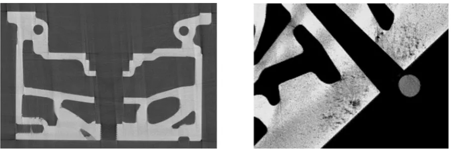
used SLS to form sand casts for production of an engine cylinder head. XCT was then used on the cast part to examine porosities produced using the casting process, concluding that this method of porosity examination was useful for rudimentary detection of pores (see figure 3).
[image:6.595.71.525.161.311.2]Figure 3. Examples of an XCT slice of an aluminium sand cast engine cylinder head and of porosities found when producing parts by this method. The authors note the sharp definition of internal cavities as a result of the relatively high SLS accuracy. Images reproduced from reference [20].
2.3 History 2005 to 2010
The 2005 to 2010 period showed an increase in the use of XCT for measurement of AM parts, specifically using XCT as a pore measurement tool. During this time, authors began to measure overall porosity through calculation of the ratio of the number of voxels representing pores to the number voxels representing solid material in an XCT scan [21], as well as performing dimensional measurements of individual pores using the method presented by Hildebrand and Rüsegger in 1997 [22]. Hildebrand and Rüsegger detailed a method of depicting complex spatial structures (i.e. pores) through distance transformations, using XCT data. Regarding overall porosity measurement, examples of this use can be found elsewhere [23-31] for a variety of AM purposes, such as: assessment of osseointegration potential, AM process comparisons, CAD/as-built comparisons, and general characterisation of tissue scaffolds and similar porous structures. The authors of references [23-31] also commonly performed more established characterisation methods such as scanning electron microscope (SEM) imaging and mechanical testing in conjunction with XCT porosity measurements, adding the XCT as a complementary technique. The 2008 paper by Heinl [24] also represents an example of the use of the aforementioned Hildebrand and Rüsegger method of pore diameter measurement [22]. In the 2010 paper by Kerckhofs et al. [31], the authors provide further novel use of XCT data alongside mechanical performance data to map strain at different loads in porous Ti-6Al-4V structures, in order to correlate structural and mechanical characteristics.
2.4 History 2010 to 2014
of XCT data, noting the effect to be particularly prevalent in highly dense parts. The authors also compared their findings to SEM micrographs, which gave porosity values similar to those gained using the Archimedes method for highly dense parts, but displayed substantially more variation. As a result of these findings, a number of subsequent studies used the Archimedes method as the sole porosity measurement [47, 48]. The Archimedes method currently remains the most appropriate method for porosity evaluation of metals in future studies, as XCT data is not yet comparably accurate. The Archimedes method of porosity measurement is possible because although the method technically measures density, it is usually possible for metals to translate the obtained density into a porosity value, as the bulk density of the metal is usually well known. It should be noted however, that in the case of polymer parts, the part density commonly varies dependent on the polymer microstructure (i.e. amorphous versus crystalline phases) and so the bulk density of AM polymers is often not well known as the microstructure depends upon the processing of the part [49, 50].
A number of authors during this period also examined the porosity of SLS polymer parts using XCT [33, 37, 44, 45]. The results of these studies differed in their findings compared to those examining metal parts, in that the Archimedes measurements used by some of these authors were not found to be as similarly accurate as found in the papers discussed above. For example, Rüsenberg et al. [33] compared Archimedes, XCT and gas pycnometer (i.e. measuring displaced gas) porosity measurements, reporting lower porosities with larger uncertainties from the Archimedes measurements that from the pycnometer measurements. Compared to the Archimedes measurements, XCT measurements reported lower porosities again, but this was attributed to the fact that the XCT samples were taken from the centre of the sample bulk, while more pores were concentrated near the edges of the part. Dupin et al. [37] similarly measured the density of SLS processed polyamide 12 using the same three methods, again reporting higher closed porosities using the Archimedes method when compared to XCT. In this study however, the authors attributed this difference to an overestimation of the closed porosity by Archimedes measurements because of the degree of crystallinity of the processed polymer having a higher density than the density of the powder measured by pycnometry.
The aforementioned studies ([32, 34, 39]) note that the Archimedes method is incapable of providing any information about the internal part geometry beyond an overall porosity, and so XCT has continued to be used for dimensional pore measurement and internal defect detection [34, 35, 39, 40, 42, 46, 47]. In addition to the measurement of pore morphology, XCT also allows visualisation of pore distribution within parts. In the paper by Léonard et al. [51] for example, the authors studied the formation of elongated pores in EBM parts, correlating to intentionally misaligned overlap regions between contour and hatched sections within parts. Similarly, Attar et al. [48] examined crack formation due to pores and unsintered powder in SLM titanium parts, using XCT to examine pore distribution.
During this period, a series of publications by Pyka et al. [38, 43, 56-58] pioneered the use of XCT data as a method of analysing surface texture, through extraction of surface texture parameters from XCT data. In a 2010 paper by Pyka et al. [56], the authors highlighted the difficulties in the measurement of surfaces in porous 3D structures by traditional methods, and so defined a protocol for XCT roughness measurement by generating profiles from 2D XCT slices. The authors measured SLM Ti-6Al-4V struts using XCT and validated the method by comparison with interferometric measurements. Texture parameters generated using both methods were shown to be similar and differences in roughness between the tops and bottoms of struts were identified by the authors. It should be noted, however, that Pyka et al. presented preliminary results; roughness parameters were quoted generally without filtration, uncertainty or confidence intervals, which is not in line with good practice for the generation of surface texture parameters [59]. Kerckhofs et al. [57] rigorously compared the surface parameters Pa, Pq and Pt of porous Ti-6Al-4V samples, measured using optical, contact and XCT methods. The data showed XCT measurements to be accurate and robust for micro-scale roughness, whilst sub-micrometre measurement was stated to be currently impossible. Pa values for rough surfaces (5 m to 30 m) were statistically similar for each technique, although optical measurements gave higher values on rougher samples due to data dropout from the presence of steep slopes (i.e. lower accuracy compared to the XCT technique). Pa values for low roughness surfaces (<1 m) were overestimated using the XCT technique and the data were highly affected by noise. Measurements of porous structures showed no differences between internal and external struts when top and bottom values were averaged, implying successful roughness measurement throughout the volume. The authors clearly discussed caveats of the technique regarding poor resolution, although did not perform any filtering of the extracted profiles (to gain texture parameters, as is common practice) and did not explain why this was not performed. Figure 4 illustrates the method of profile extraction from XCT data (from reference [57]). This method of parameter extraction was then applied in further papers by Pyka et al. [38, 58] and Van Bael et al. [43]. In the papers by Pyka et al., the authors used the technique to compare scaffold strut surface primary profiles after various surface finishing processes, while Van Bael et al. used the technique to study strut surfaces for in vitro applications. It should be stressed, however, that whilst the development of this technique holds promise for future surface measurements, the data gained are of poor resolution in comparison to established surface measurement methods, and the parameters obtained for surface texture measurement are now in the process of being supplanted by other methods of surface metrology [60]. Development of the Pyka et al. method, therefore, represents a stimulating research challenge for future work.
Figure 4. An XCT image used in the measurement of surface texture parameters, with a binarised version of the slice and the extracted profiles. Scale = 200 m. Image reproduced from [57].
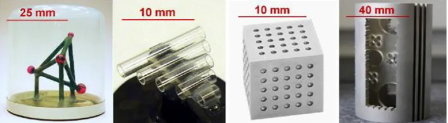
[image:8.595.70.526.530.616.2]objects for the purpose of XCT verification and calibration, and presented a number of reference objects proposed for this purpose. In the subsequent presentation by Carmignato et al. [61] and in the related paper by Carmignato [62], the authors elaborated upon the Kruth et al. review, summarising methods of accuracy evaluation of XCT dimensional measurements. Carmignato [62] also discussed performance verification and traceability establishment methods, noting the importance of XCT for measurement of AM parts. The authors further discussed the results from the first international XCT comparison of four proposed reference objects (see figure 5). In his paper, Carmignato concluded that there is a need for standards regarding performance verification and traceability, in order for XCT to be accepted as a metrological tool.
Figure 5. Reference objects used in the international XCT comparison, from left to right: CT tetrahedron, pan flute gauge, calotte cube and QFM cylinder. Image reproduced from [62].
[image:9.595.72.526.240.365.2]Figure 6. Left to right: the ‘cactus’ XCT artefact, reproduced from [63] and the NIST AM artefact of Moylan et al., reproduced from [64].
3. XCT in AM reverse engineering today
While medicine represents the most common application of XCT and AM reverse engineering [16], the technology has spread into other research areas, often for the examination and reproduction of cultural artefacts or archaeological remains. As examples of this, Laycock et al. [65] reproduced 19th
century chess pieces through digital modification of incomplete XCT data from broken and incomplete artefacts, while Howe et al. [66] used XCT data to reverse engineer historical wind
instruments with a view to producing working copies of antique models (see figure 7). Laycock et al. concluded that reconstruction using XCT with AM was possible; particularly noting that XCT data provided previously unknown information about construction methods of the original chess pieces. Howe et al. drew similar conclusions, noting that the method used showed promise for the production of historical instruments. The authors did, however, cite drawbacks relating to machine cost, as well as pore formation and surface finish as barriers to adoption of the technology due to the resulting effects on musical tone.
Figure 7. Left: XCT data of a saxophone mouthpiece, right: AM reproduced saxophone mouthpieces with original wooden mouthpiece (second from left). All the AM mouthpieces were produced by scaling of the original scan data and the rightmost mouthpiece was stated to be sufficiently dense as to operate successfully. Images reproduced from [66].
[image:10.595.74.528.446.642.2]analogue and concluded that XCT and binder-jetting are effective tools for radiolarian studies. Similarly, Henson [68] reproduced biological remains from XCT and 3D laser scanner data using binder-jetting, where comparison of the reproductions showed that XCT gave higher accuracy models compared to 3D scanner data. Henson concluded in this instance that the models produced were not sufficiently accurate for extensive skeletal research, but noted that the models allowed for population and basic morphological studies, and that they were applicable to outreach and teaching as well as for use in exhibitions. Appleby et al. [69] similarly used SLS to replicate the skeleton of Richard III from XCT data of remains famously found in a Leicester car park. The resulting model has since been exhibited, as well as used to provide new information about the king’s life and his famous spinal defect.
4. XCT in AM pore measurements today
The use of XCT for the non-destructive measurement of density and porosity, as well as the study of pore morphology and distribution, is now a well-established practice which applies particularly well to the measurement of AM parts. As one of the primary techniques currently available to evaluate pore morphology and distribution non-destructively (the other being ultrasonic NDE), XCT is increasingly being used in AM for a variety of applications and recent publications reflect this use [70-89]. A number of these publications represent novel uses of XCT in porosity measurement and will be described here in more detail. Before discussing these uses, however, it is at this point appropriate to highlight studies involving measurements of small features which are examined in essentially the same manner as pores. For example, in the paper by Slotwinski et al. [90] and the review by Slotwinski and Garboczi [91], the authors discuss using XCT to analyse the morphology of particles used in powder bed fusion. Similarly, Chlebus et al. [85] used XCT not only to measure porosity but also to quantify the amount of rhenium dissolved in molten titanium, through measurement of remnant rhenium particles in final parts. In another example of small feature measurement, Tammas-Williams et al. [83] used XCT to examine pores within a powder feedstock, as well as pores present in final parts.
4.1 Recent novel XCT porosity measurements
Figure 8. (a) Volume renderings of voids in a high porosity stainless steel sample prior to mechanical testing (left) and immediately before catastrophic failure (right). (b) XCT images at different load and displacements during in-situ tensile loading. Images reproduced from [80].
[image:12.595.73.527.123.518.2][83] used XCT in the study of compressive failure, this time in scaffolds of varying porosity produced from titanium and Ti-TiB by SLM. XCT was used to verify designed porosities and identify additional undesigned porosities, as well as to show that cracks resulting from low strut ductility in porous areas cause early-stage compressive failure. In their study of SLM processed AlSi10Mg, Maskery et al. [84] examined the effect of post-process heat treatments on pore size, position and morphology, noting no changes after annealing and precipitation hardening of samples. The authors specifically noted the usefulness of XCT in quantitative defect analysis when compared to conventional SEM cross-sectioning, as the number of micrographs required to provide a pore sample size of equivalent statistical quality would be prohibitively large. The authors in this case also identified a requirement for development of robust image analysis procedures, in particular thresholding or segmentation, in order to ensure reliable pore morphology measurements in the future.
4.2 Hybrid porosity measurements
The authors of the studies discussed in section 3 commonly used XCT as part of a larger sphere of characterisation methods to relate porosity to other part features. In continuation of this theme, several instances where XCT has been used in pore measurement with other techniques are of note; either to verify experimental measurement procedures through twin data acquisition, or as a hybrid measurement tool. In the paper by Tammas-Williams et al. [88], the authors compared XCT data to SEM metallographic cross-section data to further examine pore morphologies and showed that XCT data generally agreed with 2D cross-sectional measurements down to a lower pore size limit of ~5 m. Maskery et al. [84] stated their agreement with the pore size data presented by Tammas-Williams et al., noting very similar pore sizes in their study. Castilho et al. [86] similarly studied the dimensional accuracy, porosity and mechanical properties of binder-jetted parts as a function of binder saturation. Using the Archimedes method, SEM, XCT and high resolution photo-scanning, the authors measured physical properties, while compression tests were performed to examine mechanical properties following post-processing of parts. XCT was used with these other techniques to visualise pore distribution in part interiors, while the Archimedes method was used to evaluate overall porosity. The photo-scanner was used in this case to evaluate dimensional accuracy by measuring the scanned images.
porosity using XCT and metallographic cross-sectioning, although they used SEM micrographs as opposed to the optical microscopy used in the aforementioned papers.
The current state of XCT porosity measurement in AM is very clear from the studies discussed here. XCT is now very commonly used for the measurement of pores and similar small features, and XCT has been deemed sufficient in the detection of fatigue-critical flaws. The technique has its limitations compared to other methods of porosity quantification (such as the Archimedes method), mostly pertaining to poor resolution in comparison to the size of the smallest pores. The resolution of XCT scans is related to the size of the sample and maximum achievable magnification afforded by the XCT apparatus. The result of this is that larger samples provide lower accuracy porosity measurements because the shapes and sizes of internal pores are misrepresented. The limitations discussed here will likely only be overcome with the advancement of XCT technology. These conclusions will be discussed in more detail in section 6.1.
5. XCT in dimensional metrology of AM parts today
In addition to porosity measurements, XCT is now commonly used in general dimensional metrology as a substitute for other co-ordinate measurement techniques, in cases where traditional methods of measurement (such as CMM) are impractical. This is most notably the case with AM parts due to the aforementioned complex geometries that are now commonly present. Further to older studies discussed earlier in this review, the past year has seen many publications exploring the use of XCT for direct measurements of part features and a number of these will be discussed in the following section [5, 86, 92-111].
5.1 Validation against CAD models
One of the common foci of current work involving metrological XCT is as a method of accuracy assessment through validation against CAD models, and consideration of related measurement uncertainties and tolerancing is becoming an increasingly significant feature of these studies. Cooper et al. [106], for example, investigated the potential benefits of AM in improvement of fuel efficiency through lightweighting of engine valves, using XCT to reverse engineer FEA simulations in order to redesign the valves. Following production of the re-engineered part, the authors used XCT to validate the part against the CAD model and to detect defects. The part geometry was in good agreement with the CAD model under a tolerance of ±0.15 mm, with no significant defects detected. The authors noted difficulties in edge detection using XCT during this process and detailed steps were taken to overcome the problem by manually segmenting internal geometries. Cooper et al. concluded that XCT was used successfully as a reverse engineering tool for CAD generation and that production of a functional, lightweight part was possible using AM. Villarraga et al. [104] similarly used XCT to compare parts made by FDM and SLA, as well as to assess their inkjetted nanopositioning flexure stage for air voids and morphological accuracy. The authors performed morphological deviation and defect analyses in comparison to nominal CAD designs. In the paper that followed, Lee and Tarbutton [105] described the final results of their work and concluded through testing of the flexure stage that their method was capable of producing a cost-effective alternative to other similar stages, achieving 25 nm positional precision over a 500 m range.
5.2 Medical measurements
integrated bone volume at four and twelve weeks following implantation of tissue scaffolds in rabbit femurs, while Mroz et al. [98] evaluated post-operative integrated bone volume using XCT. These authors all particularly show development in the use of metrology in medicine due to their consideration of measurement uncertainties; representing good practice not commonly observed previously in medical studies. This consideration implies that the medical field is beginning to adopt a more rigorous approach to implant production, in appreciation of modern manufacturing technology.
5.3 Measurements of lattice structures
Lattice structures that were impossible prior to the inception of AM due to tool access constraints have been identified as a useful output of AM, as when compared to fully dense parts, components utilising lattices in the place of bulk material have been shown to retain strength whilst reducing total mass. The use of lattices in tissue engineering represents an interesting field of research, but these structures are also of interest to engineers for a wide array of applications; from support structures, to heat dissipation and energy absorption [112]. As such, the past year has seen a series of studies into lattice materials and the recent review on microlattices by Xiong et al. [103] discusses the use of XCT in measurement of AM lattices at length. Van Grunsven et al. [95], Sercombe et al. [108] and Abele et al. [110] all produced metallic lattice structures via a variety of additive processing methods, and used XCT to compare built parts to CAD models. The latter paper by Abele et al. is of particular significance in that the authors critically analysed the comparison, noting that their findings were based on a specific geometry and material, and that further research is required to generalise findings. Sercombe et al. used XCT in their study to examine the deformation and failure of scaffolds through generation of FEA mesh models, which were then shown to agree with experimental data. This study indicates the capability of XCT for the purpose of FEA model generation; agreeing with the conclusions made in 2005 by Williams et al. [113].
5.4 AM and XCT artefact development
Teeter et al. [109] recently produced a test artefact specifically dedicated to dimensional verification in AM for biomedical applications. The authors designed the artefact in reference to the biomedical focus to contain holes, cylinders, gaps and lattices; studying how positioning on the build plate affected manufacture. Results showed that in this study location on the build plate had no effect on dimensional accuracy. The minimum feature size for this material and process (SLM of stainless steel) was found to be of 0.3 mm as features designed under this size were overbuilt to at least 0.3 mm, while the average deviation between as-built parts and the nominal was shown to be uniformly less than 0.1 mm. The authors concluded that the test artefact was effective for system and material verification, as well as for determination of build plate positional effects and minimum feature size. Measurements were made generally using a measurement microscope, while lattice components were measured using XCT.
Figure 9. CAD model and top view of the Möhring et al. general test part with numbered features; reproduced from [102]. Each feature has defined purposes, generally designed to be difficult to manufacture and requiring an array of machining methods.
5.5 Hybrid dimensional measurements
As discussed in section 4.2 in regards to porosity measurements, XCT is now often used in collaboration with other measurement techniques to characterise parts, and this trend is similarly present in general dimensional measurements as well as porosity measurements. In illustration of this trend, Narra et al. [99] recently presented a method validating the mechanical behaviour of biodegradable SLA scaffolds using XCT with in-situ deformation, in which XCT measurements were made before and after compression loading using a mechanical compression device. The authors concluded in this case that the method was appropriate for validation of printed scaffolds and claimed that the related deformation fields could be used to corroborate simulated designs with as-built parts.
5.6 Relevant review work
qualitatively defining design complexity into five groups. Group one, for example, contained simple parts that could be inspected using conventional methods, whereas groups four and five comprised components producible exclusively by AM and requiring new NDE inspection techniques. The authors conducted a literature review into various NDE techniques and concluded that XCT is the most promising method for evaluation of complex geometries. The Manufacturing Technology Centre (MTC, UK) also recently produced two relevant reports reviewing the use of XCT for NDE and the use of simulation in enhancing inspection [100, 101]. In the first of these reports [100], Turner discussed the now common use of XCT in NDE, material characterisation, dimensional measurement and digitisation; through the acquisition of volumetric scan data from measured objects. Turner particularly observed how XCT is useful in NDE of AM components, due to the ability to extract internal surface data. The author further reviewed the state-of-the-art in XCT NDE and discussed several topics regarding his findings. The first of these points was in regards to the hardware trade-off during scans, discussing advantages and disadvantages of various systems. The second section addressed methods of compensation for the limitations of XCT, including: image artefacts and contrast, workpiece dimensions and penetration, and cycle time. Turner also highlighted the industrial applications of XCT, as well as the potential for future automation of the technology and the barriers to wider technological adoption. Turner noted the following as barriers to increased adoption: limited standardisation, large data volumes, system cost, a lack of understanding of system capability and personnel certification. Turner highlighted the use of XCT in AM and compared XCT to other NDE techniques (x-ray imaging, ultrasonic and acoustic resonance testing), concluding that XCT represents an attractive solution for NDE; particularly citing the lack of AM and XCT specification standards as the primary technological barrier. In the latter MTC report [101], Brierley and Akhtar summarised the latest developments in radiography for high speed inspection of AM parts. The authors examined the various commercial machines and software available; noting that there is a wealth of technologies but that high speed XCT is not possible without constraints on part size and density. Everton et al. [114] recently reviewed the current state of in-situ metrology and process monitoring for AM, in order to address the lack of quality assurance in AM parts. The authors noted the development of many approaches to in-situ measurements, finding that XCT has not yet been used in-situ, despite having the potential for in-situ AM process inspection. The authors attributed the reason for XCT not having yet been investigated for in-situ inspection to the difficulty that would be experienced integrating the technology into AM systems, in comparison to simpler camera or thermal based monitoring techniques. The authors concluded that camera and thermal based systems likely represent the future of in-situ process monitoring and control, but noted that more complex methods utilising NDE techniques capable of sub-surface inspection (such as XCT) may also be integrated in the future.
6. Conclusions and future research
The above discussion of current studies represents the state-of-the-art industrial use of XCT in AM. It is clear from the available literature that research utilising XCT and AM falls into two primary areas, although the number of unique applications is substantially in excess of this. These primary areas have been discussed in detail and it is possible to draw specific conclusions regarding each of the applications within each research area. It is of note that the majority of the literature examined in this review is in relation to AM of metal parts. While the discussion presented in this review reflects the available literature (which mainly focuses on metal AM), the conclusions made here should be assumed to be in reference primarily to metal parts unless otherwise stated. It may in some cases be possible to extrapolate the conclusions made here to cover polymer AM, but all conclusions are made in reference to the evaluated literature.
6.1 XCT for AM pore measurements
the most reliable non-destructive method of evaluating pore distribution within parts. It should however be noted that unlike XCT where a small sample is preferable to increase the achievable magnification, Archimedes measurements suffer from increased errors associated with the surface effects (bubbles attached to sample surfaces) for small samples with high surface area. Uncertainties in measurements made by the Archimedes method are also dependent on the density contrast between the sample material and the measurement fluid [34], which is low for polymer parts. Coupled with the problems discussed previously in measuring density of polymer parts using the Archimedes method, XCT can, for some parts, potentially produce better results than using the Archimedes method [33, 37]. XCT measurements can often be more accurate when compared to 2D, single layer, porosity measurements (via cross-sectioning) due to the nature of random sampling and relatively low numbers of pores. XCT is now commonly used alongside other measurements to correlate porosity and pore distribution with mechanical properties, and such studies have shown that pores routinely act as failure initiation sites. The main criticism of XCT porosity measurements is inaccuracy compared to Archimedes porosity measurements, which include information from pores of all sizes, while XCT is incapable of measuring pores smaller than the minimum voxel size. The solution to this problem is improvement of XCT resolution, which is a common focus area in XCT research.
The other main stream of future research will likely be the continued correlation of pore information with other information (e.g. mechanical) about parts, as discussed in section 4.2. As XCT scans are relatively expensive in comparison to other measurement techniques, it follows that if other measurements can provide approximate information regarding the internal geometry of parts, then the cost of verification can conceivably be reduced through the use of cheaper measurement techniques. By this, it may be possible to correlate the surface texture of an AM part with the part’s near-surface porosity (a common feature in parts produced by powder bed fusion, relating to the interaction between border and hatch scans [51]). It is therefore conceivable that a relatively cheap measurement (for example, using a contact stylus instrument) could potentially provide information about near-surface porosity.
6.2 XCT for AM in dimensional metrology
be considered non-ideal in terms of artefact design for XCT. It may also become apparent that an AM artefact more specific to XCT measurements should be developed, as the existing AM designs presented earlier do not necessarily represent objects that are easily measurable using XCT systems. Similarly, the artefacts currently used in XCT calibration and verification are not necessarily producible by additive methods, due to the resolution and material limits presented by many AM processes. For example, AM processes are not able to produce many features commonly found in reference artefacts, such as high precision spheres. As XCT will likely become the most common tool for AM product verification, the development of an AM specific XCT artefact may be required. As the precision of AM improves, it will facilitate the production of a new class of metrological artefacts to be used throughout the manufacturing sector.
An interesting area of XCT measurement that has not been widely covered is the use of XCT for the measurement of surfaces. Although resolution is generally poor compared to other surface measurement techniques, XCT scans are, as stated, the only method of measurement of internal surfaces. As shown, a number of studies have successfully extracted primary profiles from XCT data, so it follows that it should be possible to build up 3D surface maps of AM parts using similar techniques. The authors of this review therefore conclude that XCT represents an interesting potential method for the examination of internal AM surfaces. In terms of the potential limitations regarding XCT as an internal surface texture measurement method, the primary drawback of XCT in that the scan resolution strongly depends on the maximum achievable magnification, and therefore the overall part dimensions. Internal texture will naturally therefore be harder to measure for larger parts than smaller parts. A substantial limitation also exists regarding the exact determination of surfaces from XCT data. It has been shown previously that, primarily due to the beam hardening artefact, the offsets of internal edges differ from those of external edges [115]. As surfaces are often determined in reference to external surfaces, this may prove a substantial problem when examining internal surfaces.
6.3 Summary of conclusions
The combined use of XCT and AM has become increasingly important in various fields of engineering. The use of both technologies is becoming more established in advanced manufacturing and metrology, respectively, and a great deal of research has been put into increasing the use of both technologies for a range of applications within these fields. This research should continue, as adoption is not yet widespread. The following are primary barriers to the increased adoption:
In measurement of AM part porosity: two primary requirements, regarding increased resolution for the detection of small pores to allow for higher accuracy and precision in pore measurement, and correlating porosity and pore distribution measurements to more cost effective measurement techniques to potentially reduce verification costs.
In dimensional metrology of AM parts: a continuation of work regarding XCT system calibration and verification to increase technology adoption, as well as the production of new research regarding XCT measurement of surface texture.
The fields of XCT and AM have both come a long way since the first combined use of XCT and AM in the reproduction of a model skull by Mankovich et al. [15] in 1990, and XCT has progressed far beyond its roots as a reverse engineering tool since this time. The now common use of metrological XCT in engineering increasingly works in symbiosis with AM to recreate, as well as to verify, parts in a wide range of fields, and through continued research will aid in the acceptance of AM as an industrially viable manufacturing method.
Acknowledgements
References
[1] ISO/TC 213 1996 Dimensional and geometrical product specifications and verification (International Organisation for Standardization)
[2] ISO 3534-2 1993 Statistics - Vocabulary and symbols - part 2: statistical quality control (International Organisation for Standardization)
[3] Sun W, Brown S B and Leach R K 2012 An overview of industrial x-ray computed tomography NPL (London, UK: National Physical Laboratory)
[4] Kruth J-P, Bartscher M, Carmignato S, Schmitt R, De Chiffre L and Weckenmann A 2011 Computed tomography for dimensional metrology CIRP Ann. Manuf. Techn. 60 821-42
[5] De Chiffre L, Carmignato S, Kruth J-P, Schmitt R and Weckenmann A 2014 Industrial applications of computed tomography CIRP Ann. Manuf. Techn. 63 655-77
[6] Hsieh J 2009 Computed tomography: principles, design, artifacts, and recent advances (Bellingham, WA, USA: SPIE Press)
[7] Roscoe L 1988 Stereolithography interface specification 3DSystems (Rock Hill, SC, USA: 3D Systems Inc)
[8] Gibson I, Rosen D and Stucker B 2014 Additive manufacturing technologies: 3D printing, rapid prototyping, and direct digital manufacturing (New York, NY, USA: Springer)
[9] ASTM F2792 - 12a 2012 Standard terminology for additive manufacturing technologies (ASTM International)
[10] Hull C W US 4575330 A Apparatus for production of three-dimensional objects by stereolithography 11 Mar 1986
[11] Sachs E, Wylonis E, Allen S, Cima M and Guo H 2000 Production of injection molding tooling with conformal cooling channels using the three dimensional printing process Polym. Eng. Sci. 40 1232-47
[12] Zhang S, To S, Wang S and Zhu Z 2015 A review of surface roughness generation in ultra-precision machining Int. J. Mach. Tool. Manu. 91 76-95
[13] Vaezi M, Seitz H and Yang S 2013 A review on 3D micro-additive manufacturing technologies Int. J. Adv. Manuf. Tech. 67 1721-54
[14] Wijshoff H 2010 The dynamics of the piezo inkjet printhead operation Phys. Rep. 491 77-177 [15] Mankovich N J, Cheeseman A M and Stoker N G 1990 The display of three-dimensional anatomy with stereolithographic models J. Digit. Imaging 3 200-3
[16] Marro A, Bandukwala T and Mak W 2016 Three-dimensional printing and medical imaging: a review of the methods and Applications Curr. Probl. Diagn. Radiol. 45 2-9
[17] Ashley S 1993 Rapid prototyping for artificial body parts Mech. Eng. 115 50-3
[18] Berry E, Brown J, Connell M, Craven C, Efford N, Radjenovic A and Smith M 1997 Preliminary experience with medical applications of rapid prototyping by selective laser sintering Med. Eng. Phys. 19 90-6
[19] Jamieson R and Hacker H 1995 Direct slicing of CAD models for rapid prototyping Rapid Prototyping J. 1 4-12
[20] Losano F, Marinsek G, Merlo A M and Ricci M 1999 Computed tomography in the automotive field. Development of a new engine head case study Proc. Deutsche Gesellschaft Zerstörungsfreie Prüfung BB (Berlin, Germany: Deutsche Gesellschaft Zerstörungsfreie Prüfung) 10
[21] Taud H, Martinez-Angeles R, Parrot J and Hernandez-Escobedo L 2005 Porosity estimation method by X-ray computed tomography J. Petrol. Sci. Eng. 47 209-17
[22] Hildebrand T and Rüegsegger P 1997 A new method for the model‐independent assessment of thickness in three‐dimensional images J. Microsc. 185 67-75
[23] Heinl P, Müller L, Körner C, Singer R F and Müller F A 2008 Cellular Ti–6Al–4V structures with interconnected macro porosity for bone implants fabricated by selective electron beam melting Acta Biomater. 4 1536-44
[25] Kerckhofs G, Schrooten J, Elicegui L, Van Bael S, Moesen M, Lomov S V and Wevers M 2008 Mechanical characterization of porous structures by the combined use of micro-CT and in-situ loading 17th World Conf. Non-Destructive Testing (WCNDT) (Shanghai, China: WCNDT)
[26] Lopez-Heredia M A, Sohier J, Gaillard C, Quillard S, Dorget M and Layrolle P 2008 Rapid prototyped porous titanium coated with calcium phosphate as a scaffold for bone tissue engineering Biomaterials 29 2608-15
[27] Ryan G E, Pandit A S and Apatsidis D P 2008 Porous titanium scaffolds fabricated using a rapid prototyping and powder metallurgy technique Biomaterials 29 3625-35
[28] Ibrahim D, Broilo T L, Heitz C, De Oliveira M G, De Oliveira H W, Nobre S M W, Dos Santos Filho J H G and Silva D N 2009 Dimensional error of selective laser sintering, three-dimensional printing and PolyJet™ models in the reproduction of mandibular anatomy J. Craniomaxillofac. Surg. 37 167-73
[29] Ryan G, Mcgarry P, Pandit A and Apatsidis D 2009 Analysis of the mechanical behavior of a titanium scaffold with a repeating unit‐cell substructure J. Biomed. Mater. Res. B Appl. Biomater. 90 894-906
[30] Eshraghi S and Das S 2010 Mechanical and microstructural properties of polycaprolactone scaffolds with one-dimensional, two-dimensional, and three-dimensional orthogonally oriented porous architectures produced by selective laser sintering Acta Biomater. 6 2467-76
[31] Kerckhofs G, Pyka G, Loeckx D, Van Bael S, Schrooten J and Wevers M 2010 The combined use of micro-CT imaging, in-situ loading and non-rigid image registration for 3D experimental local strain mapping on porous bone tissue engineering scaffolds under compressive loading Proc. European Conference for non-Destructive Testing (ECNDT) (Moscow, Russia: European Federation for Non-Destructive Testing (EFNDT ))
[32] Duan B, Wang M, Zhou W Y, Cheung W L, Li Z Y and Lu W W 2010 Three-dimensional nanocomposite scaffolds fabricated via selective laser sintering for bone tissue engineering Acta Biomater. 6 4495-505
[33] Rüsenberg S, Schmidt L and Schmid H 2011 Mechanical and physical properties – a way to assess quality of laser sintered parts Solid Freeform Fabr. Symp. Proc. (Austin, TX, USA: University of Texas Austin) 239-51
[34] Spierings A, Schneider M and Eggenberger R 2011 Comparison of density measurement techniques for additive manufactured metallic parts Rapid Prototyping J. 17 380-6
[35] Van Bael S, Kerckhofs G, Moesen M, Pyka G, Schrooten J and Kruth. J-P 2011 Micro-CT-based improvement of geometrical and mechanical controllability of selective laser melted Ti6Al4V porous structures Mat. Sci. Eng.: A 528 7423-31
[36] Dadbakhsh S and Hao L 2012 Effect of Al alloys on selective laser melting behaviour and microstructure of in situ formed particle reinforced composites J. Alloys Compd. 541 328-34
[37] Dupin S, Lame O, Barrès C and Charmeau J-Y 2012 Microstructural origin of physical and mechanical properties of polyamide 12 processed by laser sintering Eur. Polym. J. 48 1611-21
[38] Pyka G, Burakowski A, Kerckhofs G, Moesen M, Van Bael S, Schrooten J and Wevers M 2012 Surface modification of Ti6Al4V open porous structures produced by additive manufacturing Adv. Eng. Mater. 14 363-70
[39] Truscello S, Kerckhofs G, Van Bael S, Pyka G, Schrooten J and Van Oosterwyck H 2012 Prediction of permeability of regular scaffolds for skeletal tissue engineering: a combined computational and experimental study Acta Biomater. 8 1648-58
[40] Van Bael S, Chai Y C, Truscello S, Moesen M, Kerckhofs G, Van Oosterwyck H, Kruth J-P and Schrooten J 2012 The effect of pore geometry on the in vitro biological behavior of human periosteum-derived cells seeded on selective laser-melted Ti6Al4V bone scaffolds Acta Biomater. 8 2824-34
[42] Leuders S, Thöne M, Riemer A, Niendorf T, Tröster T, Richard H and Maier H 2013 On the mechanical behaviour of titanium alloy TiAl6V4 manufactured by selective laser melting: fatigue resistance and crack growth performance Int. J. Fatigue 48 300-7
[43] Van Bael S, Desmet T, Chai Y C, Pyka G, Dubruel P, Kruth J-P and Schrooten J 2013 In vitro cell-biological performance and structural characterization of selective laser sintered and plasma surface functionalized polycaprolactone scaffolds for bone regeneration Mat. Sci. Eng.: C 33 3404-12 [44] Ghita O, James E, Trimble R and Evans K E 2014 Physico-chemical behaviour of poly (ether ketone)(PEK) in high temperature laser sintering (HT-LS) J. Mater. Process. Technol. 214 969-78 [45] Rouholamin D and Hopkinson N 2014 An investigation on the suitability of micro-computed tomography as a non-destructive technique to assess the morphology of laser sintered nylon 12 parts Proc. Inst. Mech. Eng. Pt. B: J. Eng. Manuf. 228 1529-42
[46] Ziółkowski G, Chlebus E, Szymczyk P and Kurzac J 2014 Application of x-ray CT method for discontinuity and porosity detection in 316L stainless steel parts produced with SLM technology Arch. Civ. Mech. Eng. 14 608-14
[47] Hrabe N W, Heinl P, Flinn B, Körner C and Bordia R K 2011 Compression‐compression fatigue of selective electron beam melted cellular titanium (Ti‐6Al‐4V) Journal of Biomedical Materials Research Part B: Applied Biomaterials 99 313-20
[48] Attar H, Calin M, Zhang L, Scudino S and Eckert J 2014 Manufacture by selective laser melting and mechanical behavior of commercially pure titanium Mat. Sci. Eng.: A 593 170-7
[49] Zarringhalam H, Hopkinson N, Kamperman N and De Vlieger J 2006 Effects of processing on microstructure and properties of SLS nylon 12 Mat. Sci. Eng.: A 435 172-80
[50] Gogolewski S, Czerntawska K and Gastorek M 1980 Effect of annealing on thermal properties and crystalline structure of polyamides. Nylon 12 (polylaurolactam) Colloid. Polym. Sci. 258 1130-6 [51] Léonard F, Tammas-Wiliams S, Prangnell P B, Todd I and Withers P J 2012 Assessment by x-ray CT of the effects of geometry and build direction on defects in titanium ALM parts Conf. Industrial Computed Tomography (iCT) (Wels, Austria: Shaker Verlag) 85-93
[52] Yan C, Hao L, Hussein A and Raymont D 2012 Evaluations of cellular lattice structures manufactured using selective laser melting Int. J. Mach. Tool. Manu. 62 32-8
[53] Xia Y, Zhou P, Cheng X, Xie Y, Liang C, Li C and Xu S 2013 Selective laser sintering fabrication of nano-hydroxyapatite/poly-ε-caprolactone scaffolds for bone tissue engineering applications Int. J. Nanomedicine 8 4197-273
[54] Fukuda A, Takemoto M, Saito T, Fujibayashi S, Neo M, Pattanayak D K, Matsushita T, Sasaki K, Nishida N and Kokubo T 2011 Osteoinduction of porous Ti implants with a channel structure fabricated by selective laser melting Acta Biomater. 7 2327-36
[55] Van Der Stok J, Van Der Jagt O P, Amin Yavari S, De Haas M F, Waarsing J H, Jahr H, Van Lieshout E M, Patka P, Verhaar J A and Zadpoor A A 2013 Selective laser melting‐produced porous titanium scaffolds regenerate bone in critical size cortical bone defects J. Orth. Res. 31 792-9
[56] Pyka G, Kerckhofs G, Braem A, Mattheys T, Schrooten J and Wevers M 2010 Novel micro-ct based characterization tool for surface roughness measurements of porous structures SkyScan User Meeting (Mechelen, Belgium: SkyScan User Meeting)
[57] Kerckhofs G, Pyka G, Moesen M, Van Bael S, Schrooten J and Wevers M 2013 High‐resolution microfocus x‐ray computed tomography for 3D surface roughness measurements of additive manufactured porous materials Adv. Eng. Mater. 15 153-8
[58] Pyka G, Kerckhofs G, Papantoniou I, Speirs M, Schrooten J and Wevers M 2013 Surface roughness and morphology customization of additive manufactured open porous Ti6Al4V structures Materials 6 4737-57
[59] Leach R K 2001 The measurement of surface texture using stylus instruments NPL (London, United Kingdom: National Physical Laboratory)
[61] Carmignato S, Pierobon A, Rampazzo P, Parisatto M and Savio E 2012 CT for industrial metrology-accuracy and structural resolution of CT dimensional measurements Conf. Industrial Computed Tomography (iCT) (Wels, Austria: Shaker Verlag)
[62] Carmignato S 2012 Accuracy of industrial computed tomography measurements: experimental results from an international comparison CIRP Ann. Manuf. Techn. 61 491-4
[63] Kiekens K, Welkenhuyzen F, Tan Y, Bleys P, Voet A, Kruth J and Dewulf W 2011 A test object with parallel grooves for calibration and accuracy assessment of industrial computed tomography (CT) metrology Meas. Sci. Technol. 22 115502
[64] Moylan S, Slotwinski J, Cooke A, Jurrens K and Donmez M A 2012 Proposal for a standardized test artifact for additive manufacturing machines and processes Solid Freeform Fabr. Symp. Proc. (Austin, TX, USA: University of Texas Austin) 6-8
[65] Laycock S, Bell G, Corps N, Mortimore D, Cox G, May S and Finkel I 2015 Using a combination of micro-computed tomography, CAD and 3D printing techniques to reconstruct incomplete 19th-century Cantonese chess pieces J. Comput. Cult. Herit. 7 25
[66] Howe R, Shahbazmohamadi S, Bass R and Singh P 2014 Digital evaluation and replication of period wind instruments: the role of micro-computed tomography and additive manufacturing Early Music 42 529-36
[67] Ishida N and Kishimoto N 2015 Three-dimensional imaging of the Jurassic radiolarian Protunuma? ochiensis Matsuoka: an experimental study using high-resolution x-ray micro-computed tomography Volumina Jurassica 13 77-82
[68] Henson K D 2015 Stories in bone still told: digitization and replication of the clover Site, fort ancient human remains Master's Thesis Marshall University
[69] Appleby J, Mitchell P D, Robinson C, Brough A, Rutty G, Harris R A, Thompson D and Morgan B 2014 The scoliosis of Richard III, last Plantagenet King of England: diagnosis and clinical significance Lancet 383 1944
[70] Cox S C, Thornby J A, Gibbons G J, Williams M A and Mallick K K 2015 3D printing of porous hydroxyapatite scaffolds intended for use in bone tissue engineering applications Mat. Sci. Eng.: C 47 237-47
[71] Ziegelmeier S, Christou P, Wöllecke F, Tuck C, Goodridge R, Hague R, Krampe E and Wintermantel E 2015 An experimental study into the effects of bulk and flow behaviour of laser sintering polymer powders on resulting part properties J. Mater. Process. Technol. 215 239-50
[72] Grünberger T and Domröse R 2014 Optical in‐process monitoring of direct metal laser sintering (DMLS) Laser Tech. J. 11 40-2
[73] Slotwinski J A, Garboczi E J and Hebenstreit K M 2014 Porosity measurements and analysis for metal additive manufacturing process control J. Res. Natl. Inst. Stand. Technol. 119 494-528
[74] Nassar A, Spurgeon T and Reutzel E 2014 Sensing defects during directed-energy additive manufacturing of metal parts using optical emissions spectroscopy Solid Freeform Fabr. Symp. Proc. (Austin, TX, USA: University of Texas Austin) 278-87
[75] Van Uden S, Silva-Correia J, Correlo V, Oliveira J and Reis R 2015 Custom-tailored tissue engineered polycaprolactone scaffolds for total disc replacement Biofabrication 7 015008
[76] Raguvarun K, Balasubramaniam K, Rajagopal P, Palanisamy S, Nagarajah R, Hoye N, Curiri D and Kapoor A 2015 A study of internal structure in components made by additive manufacturing process using 3 D X-ray tomography AIP Conf. Proc. vol 1650: 41st Annu. Rev. of Progress in Quantitative Nondestructive Evaluation (QNDE) vol 34 (Boise, ID, USA: AIP Publishing) 146-55 [77] Chou R, Milligan J, Paliwal M and Brochu M 2015 Additive manufacturing of Al-12Si alloy via pulsed selective laser melting JOM-J. Min. Met. Mat. S. 67 590-6
[79] Siddique S, Imran M, Rauer M, Kaloudis M, Wycisk E, Emmelmann C and Walther F 2015 Computed tomography for characterization of fatigue performance of selective laser melted parts Mater. Des. 83 661-9
[80] Carlton H D, Haboub A, Gallegos G F, Parkinson D Y and Macdowell A A 2015 Damage evolution and failure mechanisms in additively manufactured stainless steel Mat. Sci. Eng.: A 651 406–14
[81] Leuders S, Vollmer M, Brenne F, Tröster T and Niendorf T 2015 Fatigue strength prediction for titanium alloy TiAl6V4 manufactured by selective laser melting Metall. Mater. Trans. A 46 1-8 [82] Kasperovich G and Hausmann J 2015 Improvement of fatigue resistance and ductility of TiAl6V4 processed by selective laser melting J. Mater. Process. Technol. 220 202-14
[83] Attar H, Löber L, Funk A, Calin M, Zhang L, Prashanth K, Scudino S, Zhang Y and Eckert J 2015 Mechanical behavior of porous commercially pure Ti and Ti–TiB composite materials manufactured by selective laser melting Mat. Sci. Eng.: A 625 350-6
[84] Maskery I, Aboulkhair N T, Corfield M R, Tuck C, Clare A T, Leach R K, Wildman R D, Ashcroft I A and Hague R J M 2015 Quantification and characterisation of porosity in selectively laser melted Al–Si10–Mg using x-ray computed tomography Mater. Charact. 111 193–204
[85] Chlebus E, Kuźnicka B, Dziedzic R and Kurzynowski T 2015 Titanium alloyed with rhenium by selective laser melting Mat. Sci. Eng.: A 620 155-63
[86] Castilho M, Gouveia B, Pires I, Rodrigues J and Pereira M 2015 The role of shell/core saturation level on the accuracy and mechanical characteristics of porous calcium phosphate models produced by 3Dprinting Rapid Prototyping J. 21 43-55
[87] Rezayat H, Zhou W, Siriruk A, Penumadu D and Babu S 2015 Structure-mechanical property relationship in fused deposition modelling Mater. Sci. Technol. 31 895-903
[88] Tammas-Williams S, Zhao H, Léonard F, Derguti F, Todd I and Prangnell P 2015 XCT analysis of the influence of melt strategies on defect population in Ti–6Al–4V components manufactured by selective electron beam melting Mater. Charact. 102 47-61
[89] Berretta S, Evans K E and Ghita O 2015 Processability of PEEK, a new polymer for high temperature laser sintering (HT-LS) Eur. Polym. J. 68 243-66
[90] Slotwinski J, Garboczi E, Stutzman P, Ferraris C, Watson S and Peltz M 2014 Characterization of metal powders used for additive manufacturing J. Res. Natl. Inst. Stand. Technol. 119 460-93
[91] Slotwinski J A and Garboczi E J 2015 Metrology needs for metal additive manufacturing powders JOM-J. Min. Met. Mat. S. 67 538-43
[92] Wüst S, Müller R and Hofmann S 2014 3D Bioprinting of complex channels—effects of material, orientation, geometry, and cell embedding J. Biomed. Mater. Res. A 103 2258-580
[93] Todorov E, Spencer R, Gleeson S, Jamshidinia M and Kelly S M 2014 America makes: national additive manufacturing innovation institute (NAMII) project 1: nondestructive evaluation (NDE) of complex metallic additive manufactured (AM) structures DTIC (Columbus, OH, USA: Edison Welding Inst. Inc.)
[94] Moylan S, Slotwinski J, Cooke A, Jurrens K and Donmez M A 2014 An additive manufacturing test artifact J. Res. Natl. Inst. Stand. Technol. 119 429-59
[95] Van Grunsven W, Hernandez-Nava E, Reilly G C and Goodall R 2014 Fabrication and mechanical characterisation of titanium lattices with graded porosity Metals 4 401-9
[96] Huang H, Hsieh M-F, Zhang G, Ouyang H, Zeng C, Yan B, Xu J, Yang Y, Wu Z and Huang W 2015 Improved accuracy of 3D-printed navigational template during complicated tibial plateau fracture surgery Australas. Phys. Eng. Sci. Med. 38 109-17
[97] Li Y, Yang W, Li X, Zhang X, Wang C, Meng X, Pei Y, Fan X, Lan P and Wang C 2015 Improving osteointegration and osteogenesis of three-dimensional porous Ti6Al4V scaffolds by polydopamine-assisted biomimetic hydroxyapatite coating ACS Appl. Mater. Inter. 7 5715-24
doped octacalcium phosphate and hydroxyapatite thin films using pulsed laser depostion J. Biomed. Mater. Res. B Appl. Biomater. 103 151-8
[99] Narra N, Blanquer S, Haimi S, Grijpma D and Hyttinen J 2015 μCT based assessment of mechanical deformation of designed PTMC scaffolds Clin. Hemorheol. Microcirc. 60 99-108
[100] Turner N 2015 A10998 - Technology review of x-ray CT for inspection and dimensional metrology: deliverable 1: review of x-ray computed tomography for non-destructive testing applications MTC (Coventry, UK: Manufacturing Technology Centre)
[101] Brierley N and Akhtar S 2015 A11108 - Simulation enhanced inspection: deliverable 1: background review report MTC (Coventry, UK: Manufacturing Technology Centre)
[102] Möhring H-C, Kersting P, Carmignato S, Yagüe-Fabra J, Maestro M, Jiménez R, Ferraris E, Tunc L, Bleicher F and Wits W 2015 A testpart for interdisciplinary analyses in micro production engineering Procedia CIRP 28 106-12
[103] Xiong J, Mines R, Ghosh R, Vaziri A, Ma L, Ohrndorf A, Christ H J and Wu L 2015 Advanced micro‐lattice materials Adv. Eng. Mater. 17 1253–64
[104] Villarraga H, Lee C, Corbett T, Tarbutton J A and Smith S T 2015 Assessing additive manufacturing processes with X-ray CT metrology ASPE Spring Topical Meeting: Achieving Precision Tolerances in Additive Manufacturing (Raleigh, NC, USA: ASPE) 116-21
[105] Lee C and Tarbutton J A 2015 Compliance and control characteristics of an additive manufactured-flexure stage Rev. Sci. Instrum. 86 045107
[106] Cooper D, Thornby J, Blundell N, Henrys R, Williams M A and Gibbons G 2015 Design and manufacture of high performance hollow engine valves by additive layer manufacturing Mater. Des. 69 44-55
[107] Seol S K, Kim D, Lee S, Kim J H, Chang W S and Kim J T 2015 Electrodeposition‐based 3D printing of metallic microarchitectures with controlled internal structures Small 11 3896–902
[108] Sercombe T B, Xu X, Challis V, Green R, Yue S, Zhang Z and Lee P D 2015 Failure modes in high strength and stiffness to weight scaffolds produced by selective laser melting Mater. Des. 67 501-8
[109] Teeter M G, Kopacz A J, Nikolov H N and Holdsworth D W 2015 Metrology test object for dimensional verification in additive manufacturing of metals for biomedical applications Proc. Inst. Mech. Eng. Pt. H: J. Eng. Med. 229 20-7
[110] Abele E, Stoffregen H A, Klimkeit K, Hoche H and Oechsner M 2015 Optimisation of process parameters for lattice structures Rapid Prototyping J. 21 117-27
[111] Lin M, Morgan B, Jovanovic I, Hsieh C, Liu Y and Chen S 2015 Progress on the study of direct laser electron acceleration in density-modulated plasma waveguides Proc. 6th Int. Particle Accelerator Conference (IPAC) (Richmond, VA, USA: JACoW) 2723-5
[112] Evans A G, Hutchinson J W, Fleck N A, Ashby M and Wadley H 2001 The topological design of multifunctional cellular metals Prog. Mater Sci. 46 309-27
[113] Williams J M, Adewunmi A, Schek R M, Flanagan C L, Krebsbach P H, Feinberg S E, Hollister S J and Das S 2005 Bone tissue engineering using polycaprolactone scaffolds fabricated via selective laser sintering Biomaterials 26 4817-27

![Figure 2. Schematic diagrams depicting the processes of SLM, SLA and inkjetting respectively [8]](https://thumb-us.123doks.com/thumbv2/123dok_us/8660906.375183/5.595.77.528.114.286/figure-schematic-diagrams-depicting-processes-slm-inkjetting-respectively.webp)



![Figure 9. CAD model and top view of the Möhring et al. general test part with numbered features; reproduced from [102]](https://thumb-us.123doks.com/thumbv2/123dok_us/8660906.375183/16.595.72.517.280.442/figure-cad-model-mohring-general-numbered-features-reproduced.webp)
