Metal Hydrides for Concentrating Solar-Thermal Power Energy Storage
D. A. Sheppard1*, M. Paskevicius2, T. D. Humphries1, M. Felderhoff3, G. Capurso4, J. Bellosta von Colbe4, M. Dornheim4, T. Klassen4, P. A. Ward5, J. A. Teprovich Jr.5,
C. Corgnale5, R. Zidan5, D. M. Grant6, C.E. Buckley1
1 Hydrogen Storage Research Group, Fuels and Energy Technology Institute, Department of Physics, Astronomy, and Medical Radiation Sciences, GPO Box U1987,
Perth, WA 6845, Australia.
2 Interdisciplinary Nanoscience Center (iNANO) and Department of Chemistry, University of Aarhus, DK-8000, Denmark. 3 Max-Planck Institut für Kohlenforschung, Kaiser-Wilhelm-Platz 1, 45470 Mülheim an der Ruhr, Germany.
4 Helmholtz-Zentrum Geesthacht, Department of Nanotechnology, Max-Planck-Straße 1, 21502 Geesthacht, Germany. 5 Savannah River National Laboratory, Clean Energy Directorate, Aiken, SC 29808, USA.
6 Department of Mechanical, Materials and Manufacturing Engineering, University of Nottingham, Nottingham, NG7 2RD, UK.
*Corresponding Author: drew.sheppard@gmail.com
Abstract
The development of alternative methods for thermal energy storage is important for improving the efficiency and decreasing the cost for Concentrating Solar-thermal Power (CSP). We focus on the underlying technology that allows metal hydrides to function as Thermal Energy Storage (TES) systems and highlight the current state-of-the-art materials that can operate at temperatures as low as room-temperature and as high as 1100 oC. The potential of metal hydrides for thermal
storage is explored while current knowledge gaps about hydride properties, such as hydride thermodynamics, intrinsic kinetics and cyclic stability, are identified. The engineering challenges associated with utilising metal hydrides for high-temperature thermal energy storage are also addressed.
1 Introduction
Thermal energy storage using metal hydrides has been explored since the mid-1970s [1] but was generally applied at temperatures below 200 oC due to the limited
number of hydrides known at that time. In the early 1990’s, the development of low-cost magnesium hydride (MgH2) with rapid hydrogen (H2) sorption kinetics
[2-6] led to a renewed interest in the application of metal hydrides for solar thermal energy storage at temperatures of 350 oC and above. With the
commercialisation of concentrating solar-thermal power (CSP) using parabolic troughs and power towers, metal hydrides have the potential to be the next generation of thermal energy storage media [7-9]. Metal hydrides provide an alternative to the existing molten salt energy storage systems due to their impressive gravimetric and volumetric energy densities, which can be more than 10 times higher than molten salts [8]. As such, research into using metal hydrides for CSP is beginning to intensify with efforts split between: (1) metal hydrides suitable for use with current power tower technologies that operate in the 550 oC to 650 oC
range and; (2) metal hydrides that operate in the 650 oC to 800 oC range that are compatible with the next generation of power tower technology being pursued
by the U.S. Department of Energy as part of the SunShot research program [10, 11]. This research is directed towards identifying promising metal hydrides, testing their H2 sorption properties, designing tanks and test beds with active heat extraction, and testing the metal hydrides under dynamic conditions [7-9, 12-15].
Scale-up testing is required to mimic realistic operating conditions and it is clear that the engineering of the metal hydride tank and heat extraction system will be as critical as the properties of the metal hydride itself [14]. This article provides an overview that spans the last 40 years of research into the use of metal hydrides for solar thermal energy storage.
2 Utilisation of metal hydrides to store thermal energy
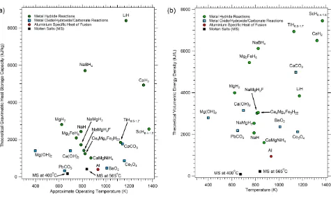
Thermal energy can be stored via reversible thermochemical reactions such as the partial oxidations of metals, the calcination of metal carbonates and the dehydration of metal hydroxides [16-19]. Unfortunately, all of these systems suffer from one or more disadvantages such as high cost, limited reversibility or capacity loss on cycling [17]. An alternative class of thermochemical candidates is represented by metal hydrides [20]. A wide range of compounds in this class can reversibly react with H2 gas over a wide range of temperatures and have theoretical heat storage capacities that substantially exceed many other thermochemical
candidates (Fig. 1). For example, the heat storage capacity of some metal hydrides are as much as 30 times higher than that available from current state-of-the-art molten nitrate salts [7]. These metal hydride compounds range from Mg2NiH4 with an operating temperature of 260 – 400 oC and a theoretical heat storage
capacity of 1117 kJ·kg−1 [21] to LiH with an operating temperature above 950 oC and a theoretical heat storage capacity of 8397 kJ·kg−1. Unlike competing
Fig. 1 (a) Theoretical heat storage capacity of various thermochemical systems including metal hydrides, metal oxides, metal hydroxides and metal carbonates. (b) Theoretical volumetric heat storage capacity of various thermochemical systems including metal hydrides, metal oxides, metal hydroxides and metal carbonates. It should be noted though that the values quoted are for the high-temperature metal hydrides only and does not consider the mass and volume of the low-temperature H2 storage. While taking into account the low-temperature H2 storage reduces the gravimetric and volumetric capacity of a MH-TES by a factor of
between 2 and 3.
A TES system using metal hydrides is comprised of a both a high-temperature metal hydride (HTMH) and a low-temperature metal hydride (LTMH). A schematic of a TES system for CSP based on metal hydrides is provided in Fig. 2 where HTMH acts as the heat storage component in the system and the LTMH acts as a hydrogen storage component. The high temperature metal hydride (HTMH) is maintained at a temperature of THT that controls the equilibrium pressure, PHT, of the hydride. The low temperature metal hydride (LTMH) is kept at a temperature TLT that controls the equilibrium pressure PLT of the hydride. The system pressure (gas pressure), PSYSTEM, will always be between the equilibrium pressures of both the low and high temperature hydrides (given adequate kinetics). In daytime operation the equilibrium pressure of the HTMH is greater than the equilibrium pressure of the LTMH (Fig. 2). In order to shift the thermochemical system from daytime to night-time operation, the equilibrium pressure of the LTMH must be larger than the equilibrium pressure of the HTMH (Fig. 2). This can be achieved by either dropping the temperature of the HTMH, THT, or by raising the temperature of the LTMH, TLT. This induces H2 to flow from the LTMH to the HTMH where it
[image:2.595.47.522.33.318.2]Fig. 2 Schematic of an energy storage system for concentrating solar thermal power. The temperature (T) and pressure (P) of both the high temperature (HT) and low temperature (LT) metal hydride beds are influenced during energy storage and release.
Cost is often pivotal when choosing to utilise a particular metal hydride as a fully operational CSP system and employing expensive coupled hydrides will never be commercially viable. Due to the incorporation of large quantities of transition or rare-earth metals, a wide range of metal hydrides are inherently expensive. These materials must be avoided despite their favourable properties due to their unrealistic industrial scale costs. Material cost is usually a function of the availability of the metal in question and the associated processing costs to obtain an optimal metal purity. As such, some consideration needs to be given to cheaper, lower purity metals that may be just as suitable as their higher purity versions. It should be noted though that hydrides with a high cost shouldn’t necessarily be excluded from consideration if their properties lead to the lowest overall installed cost.
The operating temperature used for the high temperature metal hydride is a vital property that must be considered for a CSP system. This is primarily due to the inherent efficiency of the heat engine that is defined by its operating temperature differential, a function of the temperature of the high temperature hydride. High operating temperatures of around 400 °C have been suggested in the past for metal hydride solar thermal heat storage applications [20]. Operating temperatures vary with CSP configurations and designs and they are often influenced by practical cost effective solutions to plant designs. For example the heat transfer fluid, HTF, that circulates in the parabolic collectors of a CSP solar field is limited to ~400 °C for oils, while power tower CSP design use molten salts operating at ~565 °C, and incorporation of supercritical-CO2 enables operation temperatures in excess of 650 °C [11, 25].
The operating temperature of a particular metal hydride can be expressed as a function of its enthalpy of H2 absorption, ΔH, in addition to its entropy of absorption,
ΔS. As the thermodynamics (ΔH & ΔS) define the H2 equilibrium pressure of a metal hydride at a given temperature, the potential operating temperatures and
pressures for a particular are intrinsically linked. Since ΔS is similar for most metal hydrides [26], the operating temperature is primarily related to ΔH. This means that metal hydrides that have higher enthalpies of absorption can operate at higher temperatures and lower pressures. This property is of course advantageous for the implementation of metal hydrides in CSP system: A higher heat of absorption reduces the quantity of metal hydride and hydrogen that is required for a CSP system with a fixed power output. In contrast to metal hydrides with a high operating temperature, those operating at low temperatures often exhibit small enthalpy changes. This is also advantageous as the absorption enthalpy of the LTMH determines how much heat must be exchanged with the HTF from the LTMH upon storing the H2 and how much heat must be supplied to the LTMH to release the H2.
In addition to operating temperature and pressure, there are a range of other considerations when assessing metal hydrides as thermal storage materials. These include: the kinetics of H2 absorption and desorption; the hysteresis between the H2 absorption and desorption pressures; the H2 capacity of the metal hydride;
the stability of the H2 capacity over the cycling lifetime; the variation of kinetics through the bed dependent on operating conditions; managing effective heat
transfer through the MH bed (as the thermal conductivity of most MH are low in the range of 0.1 to 0.4 W·m−1·K−1); and a containment vessel that is impervious
to H2 diffusion at the desired operating temperature.
3 Candidate Hydrides for High-Temperature Heat Storage
The potential high-temperature metal hydrides for heat storage can be classified into a number of overlapping groups. These include: (1) Simple saline or ionic hydrides of the alkali and alkaline earth metals;
(3) Complex transition metal hydrides and; (4) Magnesium-based complex hydrides. 3.1 Ionic Hydrides
The ionic, or saline, hydrides form from all of the alkali metals and the alkaline earth metals from calcium to barium [27]. As the hydrogen exists as a negatively charged ion (H−) in these compounds, their physical properties, such as brittleness, are similar to the corresponding halides. The three most well characterised
ionic hydrides are LiH, NaH and CaH2 while MgH2 is considered to be a bridge between the ionic and covalent hydrides that has sufficient similarities with the
others to be classified as an ionic hydride [28]. Lithium hydride is of interest due to its high enthalpy of formation (−181 kJ·mol−1.H2 for solid LiH and −133.5
kJ·mol−1.H2 for liquid LiH above ~690 oC) [29] and high theoretical H2 capacity (12.7 wt.% H2). However, the high temperature required to generate a H2 equilibrium
pressure of 1 bar (~950 oC), the corrosiveness of liquid LiH at this temperature and its high cost mean that, by itself, LiH is unlikely to find use as a thermal storage
medium except in niche applications. Because of its promising attributes, attempts have been made to alter the properties of LiH by the addition of secondary elements such as Si [30], Ge [31], Sn [32] and Al [33]. The secondary element acts to destabilise LiH by altering the thermodynamic pathway for H2 release. This is
illustrated for the reaction between LiH and Si (Eq. 1), where the addition of the second element reduces the 1 bar H2 equilibrium temperature from ~950 oC for
pure LiH to between 400 oC and 565 oC [30].
5/2LiH + Si ⇄ Li2.5Si + 5/4H2 (1)
Sodium Hydride (NaH) has favourable operating temperatures for CSP implementation. It has an equilibrium pressure of 1 bar H2 at 425 oC, stores 4.2 wt.% H2 and
has a high enthalpy of H2 absorption (ΔHabs = −117 kJ·mol−1.H2). However, the reversibility of the system is extremely limited. When NaH releases H2 it forms liquid
Na (melting point of 97.8 oC) and upon rehydrogenation a thin NaH layer forms on the surface of the molten Na that restricts further hydrogenation [34].
Commercial synthesis of NaH is achieved using a continuously stirred emulsion of molten sodium and mineral oil during exposure to H2 gas at ~300oC [35]. The
boiling point of mineral oil precludes the application of this technique for CSP applications above ~400oC.
A dearth of research has been performed on the CaH2 in recent years, mostly owing to the extremely high operating temperatures required for reasonable H2
pressures to be obtained. In 1939 Johnson performed PCT measurements between 778 oC and 894 oC [36]. No equilibrium plateau exists in the 0 – 20 mol.% CaH2
composition range as CaH2 dissolves in the solid Ca metal to form a solid solution. Below 900 oC and between 20 and 90 mol.% CaH2, solid solution Ca and CaH2
co-exist to form a flat plateau. Above 90 mol.% CaH2 there is a sharp rise in the equilibrium pressure and it is theorised that it is due to the formation of a solution
of Ca in CaH2. There is small or negligible hysteresis in the system and the thermodynamics have been calculated as ΔHabs = −170.2 kJ·mol−1.H2 and ΔSabs = 127.4
J·mol−1
·K−1.H2 in the temperature range of 780 to 900 oC [37]. The use of CaH2 as a solar thermal energy storage material was patented in 2010 [38] due to its
promising high temperature properties especially its high energy density: over 20 times higher than molten salts. As for LiH, containment of CaH2 is difficult due
to its corrosiveness at high temperatures.
Magnesium hydride (MgH2) has a high H2 gravimetric storage capacity of 7.6 wt.% and a high volumetric storage density of 111 kg·m−3.H2. Upon thermal treatment,
MgH2 decomposes into Mg and H2 (Eq. 2) with ΔHabs = −74.06 ± 0.42 kJ·mol−1.H2 and ΔSabs = 133.4 ± 0.7 J·mol−1 ·K−1.H2 [39]. There is little to no hysteresis despite
some mixed reports in the literature, and the plateau is flat and wide.
MgH2 ⇄ Mg + H2 (2)
Simulations and modelling of the hydrogenation and dehydrogenation of Mg/MgH2 in a TES system relies on the availability of reliable kinetic data commensurate
with operation conditions of the TES bed. The kinetics of H2 sorption in pure Mg are generally very poor [40] due to the slow hydrogen diffusion through the initial
MgH2 layer that forms on the outer surface of the particle. However, the kinetic issues have recently been overcome by introducing additives during ball milling
[21, 41, 42] that help to promote microstructure refinement of Mg/MgH2 and reduce H2 diffusion lengths. However, above 380 °C the effect of the additive can
become limited due to sintering of Mg or the reduction of oxides by Mg to form MgO that impedes the transport of hydrogen [43]. The overpressure of H2
experienced by MgH2, defined as the H2 pressure in excess of the equilibrium pressure of the metal hydride, can have a strong bearing on the kinetics and capacity.
Initially an increase in over pressure compared to the equilibrium pressure translates to an increase in the rate of the hydrogen absorption reaction. However beyond a critical over pressure, typically twice the plateau pressure, the initial reaction rate increases as expected, but decelerates during the remainder of the reaction. This is often attributed to the speed at which localised regions of MgH2 form on the surface of each Mg particle and grow together into a single continuous
outer layer [44-46]. Increases in over pressure speed up the formation of MgH2 reducing the time it takes the outer layer to reach a thickness that will inhibit the
penetration of hydrogen into the core of the particle.
Pure MgH2 exhibits very poor cycling stability where a significant reduction in the H2 storage capacity was observed after hundreds of cycles
(absorption/desorption) [20]. The phenomenon was overcome by doping the MgH2 with rather high levels of Fe. Similar success in cycling stability within the
Mg-H system has been achieved using low levels of Ni doping [47]. In general, temperatures above ~420 °C need to be avoided due to the sintering, agglomeration and capacity reduction of Mg. The Ni doped MgH2 has stable capacity of over 10,000 charge/discharge cycles as long as the temperature is maintained below 420
°C.
A MgH2 based solar thermal energy store was reported in 1994 that consisted of 24 kg of MgH2 with a cycling capacity of 5.8 wt.% and a heat storage capacity of
14 kWhth [4]. In this case, a Stirling engine with an efficiency of 20 % was utilised that gave an overall solar radiation to electricity efficiency of ~11 %. A relatively high cost, V containing Ti-Mn based LTMH H2 store was implemented in this study. One problem with using a metal hydride pair for the purpose of storing solar
energy is dealing with the heat generated during H2 sorption from the LTMH. Instead of trying to keep the LTMH near a fixed absorption or desorption temperature
it can be allowed to vary. In this case, the LTMH reached a temperature of 60 − 80 oC during absorption (which was labelled as “useable heat”) and reached −10 oC during desorption. The problem with this method is that it increases the temperature change required in the HTMH to drive H
2 between the two hydride beds.
A prototype-scale CSP apparatus has also recently been built that utilises MgH2 with active heat extraction that was paired with compressed H2 gas storage [14].
This work also showed that the H2 sorption properties of MgH2 appeared favourable, although powder compaction led to slow H2 absorption kinetics. Significant
environmental heat loss was problematic due to the small scale of the test-bed (24 g MgH2), and this heat loss is shown to be less problematic with scale-up. These
3.2 Metallic and Intermetallic Hydrides of Transition Metals
Intensive study of metallic and intermetallic transition metal hydrides began in the 1950’s due to their potential use as shielding materials in nuclear applications [48]. They are formed by the interaction of H2 with transition or rare-earth metals or their intermetallic alloys. Some high-temperature examples include TiH1.7
ΔHabs = −151 kJ·mol−1.H
2) , ZrH1.6 ΔHabs = −210 kJ·mol−1.H2), YH1.8 ΔHabs = −220 kJ·mol−1.H2), LaH1.7 ΔHabs = −198 kJ·mol−1.H2), UH3 ΔHabs = −85 kJ·mol−1.H2) and ZrNiH2.8
ΔHabs = −77 kJ·mol−1.H
2) [29, 49].
Despite their very high enthalpy of H2 absorption, the application of transition metals for heat storage is limited by two main factors: their useable H2 capacity and
their cost. In most cases only a limited fraction of the theoretical H2 capacity is available at constant pressure. That is, they have large H2 solubilities that result in
relatively short absorption/desorption plateaux (Fig. 3). Combined with the high cost of the H2 absorbing transition metals (such as Sc, Ti, V, Y, Zr, La, Ce etc.) then,
[image:5.595.38.267.167.365.2]with the possible exception of Ti [50], they can be excluded as large-scale thermal storage materials.
Fig. 3 Pressure-composition isotherms of selected transition metal hydrides [51].
3.3 Complex Transition Metal Hydrides
Hydride complexes of transition metals (TM) have been of interest for many years with the first, K2ReH9, being structurally characterised in 1964 [52]. The number
of known complexes steadily increased over time with 23 known by 1991 [53] that exploded to 127 known compounds by 2005 that cover 47 structure types [54]. This class of hydride consists of a TM-hydrogen anion complex, such as [PdH2]2−, [PtH4]4−, [NiH4]4−, [CoH5]4−, [FeH6]4−, [RuH6]4−, [MnH6]5− and [ReH9]2− [55], paired
with metal counter-cations from the alkali, alkaline earth and rare earth families (Fig. 4).
While many of the complex transition metal hydrides that belong to this group have high thermal stability that makes them potential candidates for thermal storage, they typically consist of relatively expensive elements such as Pd, Pt or Ru and decompose via multiple H2 release events that limit their economic viability.
Some examples of these include Cs2PdH4, Na2PtH4 or Eu2RuH6 and an extensive review of their synthesis, structure, bonding and properties has previously been
published [54]. A recent development in this field is the synthesis of complex Fe and Ni transition metal hydrides incorporating monovalent cations, and in some cases incorporating anionic hydrogen, and include YLiFeH6 [56], Na2Mg2NiH6 [57, 58] and Na2Mg2FeH8 [59-61] as examples. A recent analysis of the structural
properties of complex transition metal hydrides based on [NiH4]4−, [CoH5]4− and [FeH6]4− anions has determined a relationship between the cation electronegativity
Fig. 4 Ligand geometries and coordination of counter-cations of Complex transition metal hydrides. Green spheres correspond to the transition metal atoms; blue spheres are hydrogen atoms and orange spheres are the counter-cations [55, 63].
3.4 Mg-based Complex Hydrides
High temperature hydrides based on Mg are of particular interest due to their relatively low cost. While a number of Mg-based complex hydrides can be classified as complex transition metal hydrides, we have chosen to discuss them separately due to the focus on low-cost Mg as a primary component in high-temperature complex hydrides.
The synthesis and characterisation of Mg2NiH4 was first reported in 1968, along with the realisation that the compound could feasibly be employed as a H2 storage
material [64]. It was initially identified that the material undergoes reversible hydrogenation at 325 °C and 21 bar of H2 pressure (ΔHdes = −64.4 kJ·mol−1.H2) with a
theoretical H2 capacity of 3.62 wt.% H2 (Eq. 3). Although this material is easily reversible, the relatively low H2 capacity and decomposition temperature make this
material unfeasible for use as a HTMH above ~400 oC.
Mg2NiH4 ⇄ Mg2Ni + 2H2 (H2 wt.% = 3.62) (3)
Mg2FeH6, with a volumetric H2 density that is twice that of liquid H2, decomposes to the elements (Mg & Fe) upon H2 desorption, has a theoretical capacity of 5.47
wt.% H2 and a practical reversible capacity of 5 – 5.3 wt.% [24]. The H2 storage system exhibits a flat equilibrium pressure plateau with no hysteresis and a H2
absorption enthalpy of −77 kJ·mol−1.H
2. In addition, the H2 capacity remains relatively constant up to 600 cycles [24]. The high stability of Mg2FeH6 requires
590 oC have been tested and unlike for MgH2, did not affect the cyclic stability [20]. Mg2FeH6 stands as one of the most promising materials for near term
commercialisation due to the cyclic stability, advantageous temperature and pressure ranges and, of vital importance, its low cost.
In addition to Mg2FeH6, a number of mixed cation and mixed anion magnesium-based complex transition metal hydrides have been identified. Mixed cation
Mg-based complex hydrides include Na2Mg2NiH6 [57, 58], CaMgNiH4 [65], Ca4Mg4Fe3H22 [66], Ca4Mg4Co3H19 [67], Na2Mg2FeH8 [59-61] while mixed anion Mg based
hydrides include Mg2(FeH6)0.5(CoH5)0.5 [68, 69] and Mg2(FeH6)0.5(NiH4)0.5 [68]. Even though the theoretical H2 content of these phases varies between ~3.2 wt.% and
~5.0 wt.%, the few thermodynamic studies that have been performed (on CaMgNiH4, Ca4Mg3Fe3H22 and Na2Mg2FeH8) show multi-step H2 release that limits their
practical H2 capacity to around half the theoretical value (Eqs. 4 − 6) [59, 65, 66]:
2CaMgNiH4 ⇄ 2CaH2 + Mg + MgNi2 (H2 wt.% = 1.59) (4)
Ca4Mg4Fe3H22 ⇄ 2Ca2FeH6 + 4Mg + Fe + 5H2 (H2 wt.% = 2.25) (5)
Na2Mg2FeH8 ⇄ 2NaMgH3 + Fe + H2 (H2 wt.% = 1.27) (6a)
2NaMgH3 + Fe ⇄ 2NaH + 2Mg + Fe + 2H2 (H2 wt.% = 2.54) (6b)
Despite this, the high stability of the phases so far characterised ΔHabs(CaMgNiH4) = −129 kJ·mol−1.H2 and ΔHabs(Ca4Mg4Fe3H22) = −122 kJ·mol−1.H2) makes Mg-based
complex transition metal hydrides a promising class of compounds for thermal storage applications.
In addition to the Mg containing transition metal complex hydrides, there are a number of complex ternary hydrides comprised of only Mg and an alkali, alkaline or rare earth metal that have been reviewed [70]. Of most interest for thermal storage, from a cost point of view, are Ca4Mg3H14, Ca19Mg8H54 and NaMgH3. The H2
desorption from Ca4Mg3H14 and Ca19Mg8H54 have not been characterised but it is likely these materials initially decompose to CaH2 and Mg [71]. This would limit
their practical H2 capacity to 2.44 and 1.60 wt.%, respectively.
The perovskite hydride NaMgH3 (6.01 wt.% H2) can be formed readily from any combination of Na, NaH, Mg or MgH2 under a H2 atmosphere at a suitable
temperature [72] or by high energy milling [73]. Full H2 desorption follows a two-step decomposition pathway but only the first reaction is of practical interest
(4.01 wt.% H2) due to the limited reversibility of NaH (Eq. 7):
NaMgH3 NaH + Mg + H2 (7)
This system exhibits a number of advantageous properties: (1) It has a very flat H2 absorption and desorption plateau meaning it will absorb and desorb H2 at a
constant pressure regardless of composition; (2) it has negligible hysteresis (meaning absorption and desorption of H2 occurs at the same pressure) thereby
improving the efficiency of the system; (3) it has a high reaction enthalpy (−86.6 kJ·mol−1.H
2) and; (4) the cost of the raw materials is relatively low. A variation on
this system has also been studied to increase its enthalpy for solar thermal applications [12]. Fluorine incorporation in NaMgH3 to form NaMgH2F results in an
increase in the H2 absorption enthalpy to −96.8 kJ mol−1 H2. Despite having less than half the H2 capacity and thermal storage capacity of MgH2, the higher enthalpy
of NaMgH2F results in an installed system cost for CSP heat storage that is ~37 % lower than for MgH2, ~23 % lower than for Mg2FeH6 and ~18 % lower than for
NaMgH3. One current disadvantage of NaMgH2F is that the high temperature cyclic stability is problematic due to vaporisation and loss of sodium from the sample
[15].
4 Options for Low-Temperature Hydrogen Storage
4.1 Candidate Hydrides for Low-Temperature Hydrogen Storage
Typically, intermetallic hydrides are the most promising LTMHs for near-ambient H2 storage applications due to their fast kinetics and favorable thermodynamics.
Examining the Sandia DOE database reveals over 1400 intermetallic compounds based on the stoichiometries of AB, AB5, AB2 and A2B (where A = hydride forming metal such as Ti, Zr, La, Ce and B = non-hydride forming metal such as Cr, Mn, Fe, Co or Ni) [74]. There are hysteresis issues with many intermetallic hydrides that reduces overall system efficiency but these are not insurmountable. Often the properties of these intermetallic metal hydrides can be fine-tuned to match the HTMH by the addition of metal additives. It should be noted that H2 storage within metal hydrides is favorable due to the high volumetric storage density in the
solid state. However, the gravimetric H2 capacity can vary greatly between storage materials. This means that for materials with a low H2 capacity a large amount
of material is required, increasing the cost and volume of the containment system. To reduce the number of potential low-temperature H2 storage candidates a
number of criteria were established as follows: The practical H2 capacity must be greater than 1 wt.%; the equilibrium pressure of the material must be between
0.1 and 40 bar at 25 oC and; the intermetallic should not contain large proportions of rare or expensive metals.
Applying these criteria immediately excludes the A2B class of intermetallics based purely on cost. Most of these compounds consist of Ti, Zr or Hf as the A element where they exceed 60 wt.% of the total alloy weight. Of the intermetallics from the AB and AB5 classes, only TiFe and (La, Mm, Ca)Ni5 based compounds bear
considering. The AB2 class of intermetallics provide far more possibilities as Ti and Zr can partially substitute for each other as the A element while Cr, Mn, Fe, Co and Ni can readily substitute for each other over a wide range of compositions as the B element [75]. Certain alloys are commercially available such as heavily substituted Ti-Mn (Ti0.97Zr0.019V0.439Fe0.097Cr0.045Al0.026Mn1.5) [76], which have favourable properties. Other intermetallics excluded include those based on CaNi3,
which show degradation in performance for only a minimal decrease in cost compared to CaNi5 [77, 78], and solid solutions of Ti-Cr-V-Fe, which remain expensive
even when produced with cheaper forms of vanadium such as ferrovanadium [12, 79, 80].
Recently, cheaper LTMHs based on the alanate complex hydrides, such as NaAlH4 (Eq. 8) and Na3AlH6 (Eq. 9), have been investigated as replacements for the higher
cost intermetallic hydrides [13, 15, 81]:
3NaAlH4 ⇌ Na3AlH6 + 2Al + 3H2 (Habs = −38 kJ·mol−1.H2, T1bar ~32oC, H2 wt. % = 3.7) (8)
To achieve useful H2 absorption/desorption kinetics in these materials, an operational temperature of at least 100 oC is required. This is higher than that of
intermetallic hydrides, such as LaNi4.7Al0.3 (Top = 20 − 100oC, Habs = −34.0 kJ·mol−1.H2) [82] and Ti1.2Mn1.5 (Top = 0 − 80oC, Habs = −28.7 kJ·mol−1.H2) [75], but the cost
of the material is significantly less [15]. Additionally, the waste heat generated by a back pressure/condensing type steam turbine during electricity production from CSP can be utilised for desorbing H2 from the alanate systems.
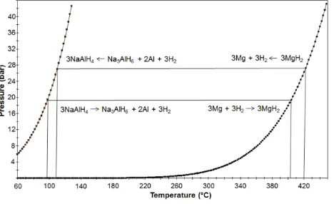
If MgH2 is chosen as the HTMH and NaAlH4 as the LTMH for H2 storage, then by considering the H2 equilibrium pressure of the two hydrides as a function of
temperature, the operating temperatures and pressures of the hydrides can be matched. Fig. 5 shows the H2 equilibrium pressure of NaAlH4 on the left side and
MgH2 on the right side. At a temperature of 95 °C the equilibrium pressure of NaAlH4 is 20 bar H2. Using this pressure for hydrogenation of Mg-metal, a temperature
[image:8.595.40.274.162.305.2]of ~400 °C is produced, which can be converted into steam for electricity production with a turbine. The reverse reaction can proceed at slightly higher temperatures for the decomposition of MgH2 producing a H2 pressure of 28 bar at ~420 °C, used for the hydrogenation of the Na3AlH6 + 2Al mixture.
Fig. 5 Equilibrium pressure curves of NaAlH4 and MgH2 used for the description of paired metal hydride systems.
The NaAlH4/MgH2 combination was used by BSR Solar Technology and the Max-Planck-Institut für Kohlenforschung to construct a demonstration project of a
Stirling engine with a thermochemical heat storage system. The LTMH was comprised of 8.5 kg of doped NaAlH4 which was combined with 10.2 kg MgH2 as the
HTMH [83]. Since a large enough quantity of NaAlH4 could not be commercially acquired at the time, the amount of NaAlH4 was too low for a complete
hydrogenation of the Mg material and the system could not be optimised. Although a short working time of the Stirling engine with the thermochemical heat storage system was demonstrated, a lack of optimisation resulted in kinetic limitations for the absorption/desorption in the NaAlH4 system [83]. The experience
from this demonstration project highlights that selecting a suitably matched HTMH and LTMH extends beyond just operating temperatures and pressures but also includes choosing metal hydride pairs with compatible kinetics.
If a waste heat source is available in the temperature range of 130 to 160 oC, then Na3AlH6 can also be used as the LTMH H2 storage material [81, 84]. The enthalpy
of H2 absorption is higher for Na3AlH6 (Habs = −47 kJ·mol−1.H2) compared to NaAlH4 (Habs = −38.6 kJ·mol−1.H2) and this may have design consequences for managing
the higher thermal load during H2 absorption. However, the kinetics of H2 absorption and desorption will also be improved for Na3AlH6 at the higher operating
temperatures [85]. One further advantage of pure Na3AlH6 compared to NaAlH4 is the much lower H2 equilibrium pressure in the temperature range of 130 oC to
160 °C. At 160 oC the equilibrium pressure for Na3AlH6 is ~20 bar and for NaAlH4 it is ~80 bar. As a consequence of this pressure difference, a significantly lighter
tank system that is based on Al alloys can be constructed when Na3AlH6 is used for H2 or heat storage systems [81].
An additional requirement for a thermal energy storage system is that of cyclic stability. While there are a number of complex hydride systems that have advantageous H2 capacities and low enthalpies to be used as LTMHs, cycling stability is a key requirement for their consideration [86-88]. Another factor that must
be considered for metal hydride TES systems is that these materials typically have low thermal conductivity that limits the effective heat transfer through the bed to the HTF and the overall efficiency of the system. The doping of alanates with additives, such as graphite and excess Al, has been shown to increase the thermal conductivity of these systems [89]. Surprisingly, the addition of these additives also helps to stabilise the reversibility of the material for extended cycling. Fig. 6 displays cycling of NaAlH4 and Na3AlH6 with the incorporation of these additives. While the practical H2 capacity of NaAlH4 is much higher than that of Na3AlH6 (~4
wt.% vs. ~1 wt.%), the cycling stability and required rehydrogenation pressure of Na3AlH6 is far superior. Interestingly, the incorporation of Al and expanded natural
graphite (ENG) to Na3AlH6 resulted in an increase H2 capacity for the entire composite. These results show promise for the use of cheaper complex metal hydrides
Fig. 6 A) NaAlH4 + 10 wt. % Al cycled at 90 bar H2 and 120 °C B) NaAlH4 + 10 wt. % Al + 10 wt. % ENG cycled at 90 bar and 120 °C C) Na3AlH6 +2 mol % TiCl3 cycled
at 150 °C and 30 bar H2 D) Na3AlH6 +2 mol % TiCl3 + 10 wt. % Al + 10 wt. % ENG cycled at 30 bar H2 and 150 °C).
4.2 Compressed Gas Hydrogen Storage
A problem with using a LTMH to store H2 gas for re-use at night time is that the LTMH itself generates appreciable quantities of heat while absorbing H2 (based on
its enthalpy of formation) and significant quantities of heat are required to release the H2. If this heat is not removed from the system during absorption then
significant self-heating of the LTMH occurs that will slow or halt the H2 absorption process. This would require an increase in the HTMH operating temperature to
generate an increased H2 pressure that would allow the H2 absorption by the LTMH to proceed. Comparable issues arise for the night cycle during endothermic H2
desorption from the LTMH and exothermic H2 absorption by the HTMH. This results in large temperature excursions in the metal hydride beds with a decrease in
the overall efficiency of the system [4]. This imposes significant constraints and costs on the internal and external design of the storage vessels to enable efficient heat transfer and to manage the heat to maintain the efficiency of the whole system.
If the heat developed by the LTMH during absorption is not stored and re-used to help release the H2 later, it represents a significant energy loss in the system.
For example, the heat released by the LTMH paired with MgH2 as a solar thermochemical heat store, represented ~30 % of the heat stored in the MgH2 [4]. As the
enthalpy of the HTMH decreases (i.e. in lower operating temperature scenarios), this fraction of heat generated by the LTMH becomes more significant and could approach 50 %, or more, of the energy stored in the HTMH. In addition, depending on the LTMH thermodynamic and kinetics properties, reduction of the plant efficiency can be observed when the heat needs to be supplied at temperatures higher than the waste heat temperature of power plant.
Storing H2 as a compressed gas has a number of advantages over a LTMH. First, the cost of the materials for the LTMH can be as much as 90 % of the total materials
cost for the entire CSP energy storage system [12] and this cost is removed in the case of compressed gas storage. Additional costs will also arise due to the construction materials and design of a LTMH tank that can deal with the thermal management issues discussed above. The disadvantages of storing H2 as a
compressed gas are the larger tank volume required compared to LTMH storage and that a compressor may be needed to boost the pressure to allowH2 absorption
by HTMH during the night cycle.
Costs for large scale above ground volumetric H2 storage in the available literature and from manufacturers are highly variable and range between ~60 USD and
~1130 USD per kg of H2 stored for pressure vessels and pipelines with ratings of between 30 and 430 bar [90-94]. Given that a CSP system using metal hydrides for
thermal energy storage would utilise several hundred tonnes of gaseous H2, determining a more accurate cost for large scale compressed H2 storage will be critical
in evaluating its economic competitiveness against H2 storage in LTMH’s. As a result, the H2 storage pressure will represent one of the most significant factors that
influence the cost and the actual feasibility of the compressed H2 storage system.
Due to the possibility of reduced cost by using a compressed H2 tank, it should be considered as a replacement for the LTMH. Burying the tank has the advantage
of producing a stable temperature environment (typically 10 − 16 oC year round), but has large costs associated with the required excavation and installation. A
[image:9.595.44.532.40.381.2]may act as thermal ballast to extract and supply this small amount of heat. If the tank is exposed to ambient conditions, the day-night temperature swing actually works against efficiency. However, suitable insulation of an above ground tank may be a less expensive option but requires further investigation.
If a compressed gas storage system is implemented then the operation of the CSP system would occur as follows. At the start of a day cycle the high temperature hydride (i.e. Mg/MgH2) will be full of H2 and the compressed gas tank will be under low pressure. The MgH2 will heat up (from solar energy) and will progressively
have to reach higher and higher temperatures to generate the pressure required to fill the compressed tank. At the end of the day cycle the high temperature hydride will be nearly exhausted of H2 (by forming metal) and a high pressure of H2 gas will be present in the compressed tank. Over the night cycle the H2 will
absorb back into the HTMH as it cools. Slowly the pressure in the compressed tank will drop as the H2 is absorbed by the HTMH. The HTMH will have to reach
progressively lower temperatures to absorb under the supplied pressure. This will result in a non-constant (variable) power output from the heat engine overnight due to a variable turbine inlet temperature that results from the HTMH absorbing H2 under progressively lower pressures. The power plant efficiency variation, as
well as the plant capacity factor, assessment will be part of another publication.
The associated costs relating to tank size and heat engine efficiency need to be weighed to evaluate whether this system is viable. A likely scenario for using a pressurised H2 tank would be in conjunction with a high temperature hydride operating in the temperature range of 450 − 650 oC and in the pressure range of 50
− 150 bar. It would potentially be cheaper than a LTMH based option. The high pressure system does not have any pressure hysteresis and is in effect equivalent to a metal hydride with a large sloped plateau.
5 Heat transfer and other engineering considerations
As stated in the introduction, the hydride tank design and engineering of the system will present their own challenges due to dual issues presented by the high operating temperatures and the use of hydrogen gas. The temperature range between 450 °C and, in the extreme cases, 950 °C, contemplated in this implementation of metal hydrides are mainly above the self-ignition temperature of hydrogen [95], although other values have been quoted [96]. It can thus be agreed that even without the ignition source of hot surfaces, which is almost unavoidable under these circumstances, hydrogen can ignite in the case of a leak. Therefore, the highest safety standards and good engineering are required to reduce this risk to manageable levels.
There are two important engineering parameters to consider when using metal hydrides to store heat: how to transfer the heat in an efficient way and which structural materials to use for the tank hull in order to achieve safe operation.
5.1 Heat transfer considerations
In CSP applications, heat transfer at high temperatures is obviously an essential part of the plant design. The concentrating heliostats must pass the solar energy to some medium in order to bring this energy to the generators that will turn it into usable electricity. Due to price and availability, there are two main heat transfer media in use today: water (steam) and air. Steam is a well-established heat transfer medium [97], known for more than 2000 years, although the first recorded successful commercial use of a steam engine is acknowledged to have happened only in 1712 in Thomas Newcomen’s “atmospheric engine” for pumping water out of a mine. Superheated steam at temperature levels of around 450 °C, while a more recently developed way to transfer energy, was already in use in the 1940’s [98]. The advantages of steam are: easy availability, established knowledge base, low price, excellent heat transfer properties (see Table 1), absence of health dangers and environmental benignity. Water does have some drawbacks as a heat transfer medium including: corrosion of pipes at high temperatures, decomposition at even higher temperatures (realistically, this is not a problem at all unless catalysts for this process happen to be in the composition of the piping) and the impossibility of using the heat of evaporation if superheated steam is to be maintained throughout. Due to this wealth of advantages and lack of significant drawbacks, steam is used in almost every CSP plant in existence [97].
Air is used only in CSP plants operating at extremely high temperatures [99], as is the case for central tower receivers. In the focus of the heliostats, temperatures above 1000 °C can exist and water would decompose into hydrogen and oxygen. Even if this effect can be avoided, the slightest contamination would cause trouble at these temperatures. Air, on the other hand, despite having significantly inferior heat capacity and heat conductivity compared to steam and supercritical water (see Table 1), is stable at these temperatures and can be pumped at high speed and volumetric flow. The properties shown in Table 1 are for N2 and O2; those of
[image:10.595.37.528.615.752.2]air lie somewhere in between (the weighted average using air’s composition is somewhat complex due to non-ideality of the gases under these conditions). Its availability is obviously even better than that of water and all other properties are similar to the ones mentioned for water. Usually, hot air is not directly used in a turbine but employed to generate steam.
Table 1 Some properties of heat transfer agents (according to Ref [100] unless otherwise specified).
Agent P
(bar)
T (°C)
Cp (J·g−1·K −1)
Din. Viscosity (Pa.s)(x105)
(kg·m−3)
(W·m−1·K −1)
Superheated steam
60 450 2.4376 2.657 19.17 0.0661
Supercritical water
225 450 4.4903 2.831 92.895 0.099
Supercritical CO2 80 450 1.1746 3.297 58.37 0.0527
He 30 450 5.1911 3.677 1.9873 0.2892
N2 30 450 1.1095 3.378 13.806 0.0514
O2 30 450 1.0424 3.967 15.834 0.0605
Na [101] 1 527 1.2603 22.7 846 [102] -
NaNO2/KNO3, 52.4
mol.% NaNO2
1 275 - 427 1.469 [103] - 1780 -
especially the complex ones, will result in a powerful exothermic oxidation reaction. Alkali and earth-alkali metals will combine with the O2 in water, liberating
massive amounts of H2 and the bursting of the reactor walls is likely to ensue. Counter-intuitively, air could, in the case of a leakage into the hydride bed, be the
lesser evil, since oxidation of the metals in the hydrides will result in temperature flares, but not in uncontrolled H2 generation. In both cases, however, the
combination of O2 in the heat transfer medium and H2 in the hydride loop will result in fires or explosions. Therefore, it may be a good idea to look into alternatives
for the heat transfer media.
Due to the high temperature levels of CSP applications, there is not a very wide range of possible other agents to transfer heat. They can be classified into liquids, gases and supercritical fluids.
Liquids. The agents that remain liquid (do not boil) at temperatures above 450 °C are either metals (like sodium), salts (like the NaNO2.KNO3 mixture,
hitherto used as a phase-change material for heat storage but decompose above 600 oC) or ionic liquids (which however tend to decompose above 200
− 400 °C, since they are usually hydrocarbon compounds) [25]. They all share the advantage of good heat exchange qualities due to reasonable heat capacities (see Table 1), as well as much higher density than gases. Therefore, they can be pumped at acceptable cost and do not decompose under operating conditions. In the same way, they usually share the drawback of being extremely corrosive (requiring special alloys for the piping) and becoming solid at temperatures higher than ambient conditions. Therefore, care has to be taken that the temperature in the circuit is kept above the melting point of the agent of choice to avoid sudden flow disruptions due to solids in the lines. In the specific case of usage together with hydrides, metals like Na have the capability to react at high temperatures with some of the components of the hydride. However, these reactions are less violent than the oxidation that was mentioned above and result in the inertisation of the hydride system, not seldom by forming alloys with the metals in the hydride. Sometimes the heat exchange agent is even part of the hydride: in the case of NaAlH4 for instance, a leak of Na would be practically harmless,
since Na is already in the composition of the hydride.
Gases. As already stated for air, gases have, due to their lower density, the need to be pumped at higher speeds to produce the same heat transfer effect as liquids. That said, their chemical stability makes them less prone to corrode piping or decompose under operational conditions. Inert gases, not containing O2 or other reactive species, can mix with the various hydrides considered above without adverse effects. This is the case for N2, Ar and
He. A special case would be the usage of H2 itself to transfer heat. Since this gas is already used in the hydride-based heat storage system, it would
make sense to use it as heat transfer medium. H2 has the advantage of having the best heat capacity and heat conductivity of all the gases mentioned
above, yielding a most efficient heat transfer medium. Only its flammability makes it less of a contestant in comparison with N2, Ar or He.
Supercritical fluids. The definition of a supercritical fluid (SCF) is any substance that the temperature and pressure are higher than their critical values, and which has a density close to or higher than its critical density [104]. As such, they are fluids above the critical point of pressure and temperature and the properties are often described as a “hybrid of those of a liquid and a gas.” On one hand, they fill containers like a gas. On the other, their density is higher than that of gases and can be comparable to that of liquids depending on conditions. With the higher density come better heat conductivity and heat capacity, thus yielding good heat exchange agents. The main candidates are supercritical CO2 and supercritical water. In the first case, the
supercritical point lies at 304.1 K and 74 bar [100]. These conditions are easily surpassed during operations in a CSP system. Only the fact that CO2
contains O2 and can therefore react with hydrides is a disadvantage for use in our application. Supercritical water shares this disadvantage. With a
critical point at 647.1 K and 221 bar [100] it is still usable from an engineering point of view, but requires the pressure resistance of the piping to be increased to levels that may render this option uneconomical.
As can be seen, heat transfer at high temperatures and, in some cases high pressures poses a challenging engineering problem. Although solvable in a variety of ways, the user needs to take into consideration the cost of the system and especially the comparison with extant, less powerful but quite economical alternatives. Other engineering challenges, such as the tank hull alloys, sealings, etc. will be addressed in future publications. Only when the whole system can provide better performance at a comparable or lower cost there will be the possibility of implementing hydrides as heat storage materials in a massive scale.
6 Challenges and Outlook
The characterisation of high temperature metal hydrides for CSP applications is still in its infancy. Further research must be directed towards accurately measuring the properties and suitability of high temperature metal hydrides, in addition to identifying further hydrides that are cost effective and suitable for high temperature energy storage. Preliminary techno-economic investigations demonstrate high potential of TES based on MH materials to compete with traditional molten salt TES systems based on sensible heat storage. Results reported in the literature [12, 13, 105, 106] show installed cost values on the order of 25-30 $/kWhth for currently available MH materials. The costs for the actual molten salt systems are on the order of 30-32 $/kWhth as reported in Reference [107] which makes the MH based TES a highly competitive solution in terms of economic performance compared to the current systems. The next step in development should be the testing of metal hydrides at high temperature on a prototype and then pilot scales to assess their ability to perform under dynamic and realistic operating conditions for CSP.
In addition to the challenge of finding low-cost metal hydrides that are suitable for high temperature thermal energy storage, there are a number of technical challenges that must also be addressed. These primarily relate to the difficulty in containing gaseous hydrogen at high temperature, the poor thermal conductivity of metal hydrides and the development of appropriate safety standards but, with significant energy density advantages of metal hydrides, there is great promise in these materials for storing thermal energy on a large scale.
References
1. G.G. Libowitz, In Proceedings of the 9th Intersociety Energy Conversion Engineering Conference, (New York, 1974), p. 322-325 2. B. Bogdanović, A. Ritter, B. Spliethoff, Angew. Chem., Int. Ed. Engl. 29, 223 (1990)
3. B. Bogdanović, T.H. Hartwig, B. Spliethoff, Int. J. Hydrogen Energy 18, 575 (1993) 4. M. Groll, A. Isselhorst, M. Wierse, Int. J. Hydrogen Energy 19, 507 (1994)
5. B. Bogdanović, A. Ritter, B. Spliethoff, K. Straburger, Int. J. Hydrogen Energy 20, 811 (1995)
8. M. Fellet, C.E. Buckley, M. Paskevicius, D.A. Sheppard, MRS Bulletin 38, 1012 (2013)
9. Q. Lai, M. Paskevicius, D.A. Sheppard, C.E. Buckley, A.W. Thornton, M.R. Hill, Q. Gu, J. Mao, Z. Huang, H.K. Liu, Z. Guo, A. Banerjee, S. Chakraborty, R. Ahuja, K.-F. Aguey-Zinsou, ChemSusChem 8, 2789 (2015)
10. US Department of Energy, D.O.E. ARPA-E High Energy Advanced Thermal Storage - DE-FOA-0000471. (2011), https://arpa-e-foa.energy.gov/FileContent.aspx?FileID=79a5de09-8bfd-4590-9cb4-e42578248d90, Accessed 27 August 2015
11. SunShot Vision Study, Chapter 5: Concentrating Solar Power: Technologies, Cost, and Performance (US Department of Energy, 2012) 12. D.A. Sheppard, C. Corgnale, B. Hardy, T. Motyka, R. Zidan, M. Paskevicius, C.E. Buckley, RSC Adv. 4, 26552 (2014)
13. C. Corgnale, B. Hardy, T. Motyka, R. Zidan, J. Teprovich, B. Peters, Renewable and Sustainable Energy Reviews 38, 821 (2014) 14. M. Paskevicius, D.A. Sheppard, K. Williamson, C.E. Buckley, Energy, doi: 10.1016/j.energy.2015.05.068 (2015)
15. P.A. Ward, C. Corgnale, J. Teprovich, T. Motyka, B. Hardy, B. Peters, R. Zidan, J. Alloys Compd. 645, S374 (2015) 16. M. Felderhoff, R. Urbanczyk, S. Peil, Green 3, 113 (2013)
17. P. Pardo, A. Deydier, Z. Anxionnaz-Minvielle, S. Rougé, M. Cabassud, P. Cognet, Renewable and Sustainable Energy Reviews 32, 591 (2014) 18. S. Kuravi, J. Trahan, D.Y. Goswami, M.M. Rahman, E.K. Stefanakos, Prog. Energy Combust. Sci. 39, 285 (2013)
19. Y. Tian, C.Y. Zhao, Appl. Energy 104, 538 (2013) 20. M. Felderhoff, B. Bogdanović, Int J Mol Sci 10, 325 (2009)
21. G. Barkhordarian, T. Klassen, R. Bormann, J. Alloys Compd. 364, 242 (2004) 22. T. Gamo, Y. Moriwaki, N. Yanagihara, T. Iwaki, J. Less-Common Met. 89, 495 (1983)
23. P. Dantzer, Metal-Hydride Technology: A Critical Review, In Topics in Applied Physics, (Springer-Verlag, Berlin, 1997), p. 279-340 24. B. Bogdanović, A. Reiser, K. Schlichte, B. Spliethoff, B. Tesche, J. Alloys Compd. 345, 77 (2002)
25. N. Boerema, G. Morrison, R. Taylor, G. Rosengarten, Solar Energy 86, 2293 (2012) 26. M.V. Lototskyy, V.A. Yartys, B.G. Pollet, R.C.B. Jr., Int. J. Hydrogen Energy 39, 5818 (2014)
27. G.G. Libowitz, The Solid-State Chemistry of Binary Metal Hydrides. (W. A. Benjamin, Inc., New York, 1965), p 139
28. C.B. Magee, Saline Hydrides, In Metal Hydrides, ed. by W.M. Mueller, J.P. Blackledge, G.G. Libowitz (Academic Press, Inc, New York, 1968), p. 791 29. F.D. Manchester, A. San-Martin, Phase Diagrams of Binary Hydrogen Alloys. (ASM International, Ohio, 2000),
30. J.J. Vajo, F. Mertens, C.C. Ahn, R.C. Bowman, B. Fultz, J. Phys. Chem. B 108, 13977 (2004)
31. M.A. Abbas, D.M. Grant, M. Brunelli, T.C. Hansen, G.S. Walker, Phys. Chem. Chem. Phys. 15, 12139 (2013) 32. A. Jain, H. Miyaoka, T. Ichikawa, Y. Kojima, J. Alloys Compd. 580, S211 (2013)
33. E. Veleckis, J. Less-Common Met. 73, 49 (1980)
34. S. Landa, B. Lebl, J. Mostecky, V. Prochazka, J. Stuchlik, J. Vit, (US3535078 A, 1970) 35. W. Fedor, M.D. Banus, D. Ingalls, Ind. Eng. Chem. 49, 1664 (1957)
36. W.C. Johnson, M.F. Stubbs, A.E. Sidwell, A. Pechukas, J. Am. Chem. Soc. 61, 318 (1939) 37. R.W. Curtis, P. Chiotti, J. Phys. Chem. 67, 1061 (1963)
38. W. Bliesner, (WO 2010/147674 A2, 2010)
39. M. Paskevicius, D.A. Sheppard, C.E. Buckley, J. Am. Chem. Soc. 132, 5077 (2010)
40. N. Gérard, S. Ono, Hydride Formation and Decomposition Kinetics, In Hydrogen in Intermetallic Compounds II, ed. by L. Schlapbach (Springer-Verlag, New York, 1992)
41. K.F. Aguey-Zinsou, T. Nicolaisen, J.R. Ares Fernandez, T. Klassen, R. Bormann, J. Alloys Compd. 434-435, 738 (2007) 42. M.P. Pitt, M. Paskevicius, C.J. Webb, D.A. Sheppard, C.E. Buckley, E.M. Gray, Int. J. Hydrogen Energy 37, 4227 (2012) 43. P.A. Huhn, M. Dornheim, T. Klassen, R. Bormann, J. Alloys Compd. 404, 499 (2005)
44. H.-Y. Tien, M. Tanniru, C.-Y. Wu, F. Ebrahimi, Int. J. Hydrogen Energy 34, 6343 (2009) 45. G. Friedlmeier, M. Groll, J. Alloys Compd. 253, 550 (1997)
46. I. Konstanchuk, K. Gerasimov, J.L. Bobet, J. Alloys Compd. 509, S576 (2011) 47. A. Reiser, B. Bogdanovic, K. Schlichte, Int. J. Hydrogen Energy 25, 425 (2000)
48. W.M. Mueller, J.P. Blackledge, G.G. Libowitz, (Academic Press, Inc., New York, 1968), p. 791 49. G.G. Libowitz, H.F. Hayes, T.R.P. Gibb, The Journal of Physical Chemistry 62, 76 (1958) 50. E. Rönnebro, G. Whyatt, M. Powell, M. Westman, F. Zheng, Z. Fang, Energies 8, 8406 (2015)
51. F.D. Manchester, In Monograph Series on Alloy Phase Diagrams, ed. by T.B. Massalski (ASM International, Materials Park, 2000), p. 322 52. S.C. Abrahams, A.P. Ginsberg, K. Knox, Inorg. Chem. 3, 558 (1964)
53. W. Bronger, Angew. Chem., Int. Ed. Engl. 30, 759 (1991)
54. K. Yvon, G. Renaudin, Hydrides: Solid State Transition Metal Complexes, In Encyclopedia of Inorganic Chemistry, (John Wiley & Sons, Ltd, 2006) 55. K. Yvon, Chimia 52, 613 (1998)
56. M. Matsuo, H. Saitoh, A. Machida, R. Sato, S. Takagi, K. Miwa, T. Watanuki, Y. Katayama, K. Aoki, S.-i. Orimo, RSC Adv. 3, 1013 (2013) 57. K. Kadir, D. Noréus, Inorg. Chem. 46, 3288 (2007)
58. M. Orlova, J.-P. Rapin, K. Yvon, Inorg. Chem. 48, 5052 (2009)
59. T.D. Humphries, M. Matsuo, G. Li, S.-i. Orimo, Phys. Chem. Chem. Phys. 17, 8276 (2015)
60. T.D. Humphries, S. Takagi, G. Li, M. Matsuo, T. Sato, M.H. Sørby, S. Deledda, B.C. Hauback, S. Orimo, J. Alloys Compd. 645, S347 (2015) 61. S. Takagi, T.D. Humphries, K. Miwa, S. Orimo, Appl. Phys. Lett. 104, 203901 (2014)
62. T.D. Humphries, D.A. Sheppard, C.E. Buckley, Chem. Commun. 51, 11248 (2015)
63. S. Takagi, Y. Iijima, T. Sato, H. Saitoh, K. Ikeda, T. Otomo, K. Miwa, T. Ikeshoji, K. Aoki, S.-i. Orimo, Angewandte Chemie International Edition 54, 5650 (2015) 64. J.J. Reilly, R.H. Wiswall, Inorg. Chem. 7, 2254 (1968)
65. B. Huang, K. Yvon, P. Fischer, J. Alloys Compd. 178, 173 (1992) 66. B. Huang, K. Yvon, P. Fischer, J. Alloys Compd. 190, 65 (1992) 67. B. Huang, K. Yvon, P. Fischer, J. Alloys Compd. 227, 121 (1995)
68. L.A. Baum, M. Meyer, L. Mendoza-Zelis, Int. J. Hydrogen Energy 33, 3442 (2008) 69. S. Deledda, B.C. Hauback, Nanotechnology 20, 204010 (2009)
70. K. Yvon, B. Bertheville, J. Alloys Compd. 425, 101 (2006)
71. Y. Kim, D. Reed, Y.-S. Lee, J.Y. Lee, J.-H. Shim, D. Book, Y.W. Cho, J. Phys. Chem. C 113, 5865 (2009) 72. D.A. Sheppard, M. Paskevicius, C.E. Buckley, Chem. Mater. 23, 4298 (2011)
73. H. Reardon, N. Mazur, D.H. Gregory, Prog. Nat. Sci. 23, 343 (2013)
74. US Department of Energy, Hydrogen Storage Materials Database. http://www.hydrogenmaterialssearch.govtools.us/, Accessed 27 August 2015 75. T. Gamo, Y. Moriwaki, N. Yanagihara, T. Yamashita, T. Iwaki, Int. J. Hydrogen Energy 10, 39 (1985)
76. J.A. Murshidi, M. Paskevicius, D.A. Sheppard, C.E. Buckley, Int. J. Hydrogen Energy 36, 7587 (2011) 77. S. Chumphongphan, M. Paskevicius, D.A. Sheppard, C.E. Buckley, Int. J. Hydrogen Energy 37, 7586 (2012) 78. S. Chumphongphan, M. Paskevicius, D.A. Sheppard, C.E. Buckley, Int. J. Hydrogen Energy 38, 2325 (2013) 79. D.N. Harries, M. Paskevicius, D.A. Sheppard, T.E.C. Price, C.E. Buckley, Proc. IEEE 100, 539 (2012) 80. G. Sandrock, J. Alloys Compd. 293-295, 877 (1999)
83. Flexibles Hochtemperatur-System für Dezentrale Stromerzeugung: Stirlingmaschine mit thermochemischem Speicher, ('BSR Solar Technologies' Max-Planck-Institut für Kohlenforschung, 2005)
84. R. Urbanczyk, S. Peil, D. Bathen, C. Heßke, J. Burfeind, K. Hauschild, M. Felderhoff, F. Schüth, Fuel Cells 11, 911 (2011) 85. W. Luo, K.J. Gross, J. Alloys Compd. 385, 224 (2004)
86. W. Luo, K. Stewart, J. Alloys Compd. 440, 357 (2007)
87. D.E. Demirocak, S.S. Srinivasan, M.K. Ram, J.N. Kuhn, R. Muralidharan, X. Li, D.Y. Goswami, E.K. Stefanakos, Int. J. Hydrogen Energy 38, 10039 (2013) 88. G. Xia, D. Li, X. Chen, Y. Tan, Z. Tang, Z. Guo, H. Liu, Z. Liu, X. Yu, Adv. Mater. (Weinheim, Ger.) 25, 6238 (2013)
89. P. Adelhelm, P.E. de Jongh, J. Mater. Chem. 21, 2417 (2011)
90. Wei Zhang, Fei Ren, Zhili Feng, Jy-An Wang, Manufacturing Cost Analysis of Novel Steel/Concrete Composite Vessel for Stationary Storage of High-Pressure Hydrogen, (Oak Ridge National Laboratory, 2012), ORNL/TM-2013/113
91. W.A. Amos, Costs of Storing and Transporting Hydrogen, (Golden, 1998), NREL/TP-570-25106
92. R. Kottenstette, J. Cotrell, Hydrogen Storage in Wind Turbine Towers, (Golden, 2003), NREL/TP-500-34656
93. W.C. Leighty, J. Holloway, R. Merer, B. Somerday, C.S. Marchi, G. Keith, D.E. White, Compressorless Hydrogen Transmission Pipelines Deliver Large-scale Stranded Renewable Energy at Competitive Cost, (Juneau, 2006)
94. T.-P. Chen, Hydrogen Delivery Infrastructure Options Analysis, (2010), DE-FG36-05GO15032 95. Safety Standard for Hydrogen and Hydrogen Systems, (NASA, 1997), Report NSS 1740.16
96. IEC, Electrical apparatus for explosive gas atmospheres - Part 20: Data for flammable gases and vapours, relating to the use of electrical apparatus, (Massachusetts, 1986), p. 59
97. M. Medrano, A. Gil, I. Martorell, X. Potau, L.F. Cabeza, Renewable & Sustainable Energy Reviews 14, 56 (2010) 98. The Battleship Bismarck. http://www.kbismarck.com/propulsioni.html, Accessed 27 August 2015
99. A.L. Avila-Marin, M. Alvarez-Lara, J. Fernandez-Reche, Proceedings of the Solarpaces 2013 International Conference 49, 705 (2014)
100. E.W. Lemmon, M.O. McLinden, D.G. Friend, "Thermophysical Properties of Fluid Systems" in NIST Chemistry WebBook, NIST Standard Reference Database Number 69. (National Institute of Standards and Technology, Gaithersburg MD, 20899, http://webbook.nist.gov, ), Accessed 27 August 2015
101. J.K. Fink, L. Leibowitz, Thermodynamic and Transport Properties of Sodium Liquid and Vapor, (Argonne Natioal Laboratory, 1995), ANL/RE-95/2
102. Density of Molten Salts and Representative Salts. http://moltensalt.org/references/static/downloads/pdf/element-salt-densities.pdf, Accessed 27 August 2015
103. Y. Iwadate, I. Okada, K. Kawamura, J. Chem. Eng. Data 27, 288 (1982)
104. P.G. Jessop, W. Leitner, Supercritical Fluids as Media for Chemical Reactions, In Chemical Synthesis Using Supercritical Fluids, (Wiley-VCH Verlag GmbH, 2007), p. 1-36
105. D.A. Sheppard, T.D. Humphries, C.E. Buckley, Applied Physics A submitted, APYA-D-1501572 (2015)

![Fig. 3 Pressure-composition isotherms of selected transition metal hydrides [51].](https://thumb-us.123doks.com/thumbv2/123dok_us/8658876.374883/5.595.38.267.167.365/fig-pressure-composition-isotherms-selected-transition-metal-hydrides.webp)


![Table 1 Some properties of heat transfer agents (according to Ref [100] unless otherwise specified)](https://thumb-us.123doks.com/thumbv2/123dok_us/8658876.374883/10.595.37.528.615.752/table-properties-heat-transfer-agents-according-unless-specified.webp)
